background image

MS-7680 Mainboard

English

En-13

MS-7680 Mainboard

English

Back Panel

Mouse/Keyboard

The standard PS/2

®

 mouse/keyboard DIN connector is for a PS/2

®

 mouse/keyboard.

USB 2.0 Port

The USB 2.0 port is for attaching USB devices such as keyboard, mouse, or other USB-

compatible devices.

USB 3.0 Port (optional)

USB 3.0 port is backward-compatible with USB 2.0 devices. Supports data transfer rate 

up to 5 Gbit/s (SuperSpeed).

Important

If you want to use a USB 3.0 device, you must use the USB 3.0 cable to connect to the 

USB 3.0 port.

HDMI Port (optional)

The High-Definition Multimedia Interface (HDMI) is an all-digital audio/video interface 

capable of transmitting uncompressed streams. HDMI supports all TV format, includ-

ing standard, enhanced, or high-definition video, plus multi-channel digital audio on a 

single cable.

VGA Port

The DB15-pin female connector is provided for monitor.

DVI-D Port

The DVI-D (Digital Visual Interface - Digital) connector allows you to connect a LCD 

monitor. It provides a high-speed digital interconnection between the computer and its 

display device. To connect an LCD monitor, simply plug your monitor cable into the DVI 

-D connector, and make sure that the other end of the cable is properly connected to 

your monitor (refer to your monitor manual for more information.)

Important

The HDMI, VGA and DVI-D display interfaces on the mainboard are designed to serve 

as  IGP  (Integrated  Graphics  Processor)  used.  If  you  installed  a  processor  without 

integrated graphics chip, these display ports will have no effect.

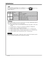
LAN

HDMI Port

Line-In

Line-Out

Mic

VGA Port

USB 3.0 Port

DVI-D Port

RS-Out

CS-Out

SS-Out

Mouse/ Keyboard

USB 2.0 Port

USB 2.0 Port

(optional)

(optional)

(optional)

Summary of Contents for H67MA-E35 B3 series

Page 1: ...H67MA E35 B3 H67MS E23 B3 series MS 7680 v2 x Mainboard G52 76801XT...

Page 2: ...poration AMI is registered trademark of American Megatrends Inc Award is a registered trademark of Phoenix Technologies Ltd Sound Blaster is registered trademark of Creative Technology Ltd Realtek is...

Page 3: ...ons and warnings on the equipment should be noted Never pour any liquid into the opening that can cause damage or cause electrical shock If any of the following situations arises get the equipment che...

Page 4: ...ct the interference by one or more of the measures listed below Reorient or relocate the receiving antenna Increase the separation between the equipment and receiver Connect the equipment into an outl...

Page 5: ...Elektronik Altger te nicht mehr als kommunale Abf lle entsorgt werden MSI hat europaweit verschiedene Sammel und Recyclingunternehmen beauftragt die in die Europ ische Union in Verkehr gebrachten Prod...

Page 6: ...e producten die de merknaam MSI dragen en verkocht zijn in de EU Deze goederen kunnen geretourneerd worden op lokale inzamelingspunten SRPSKI Da bi za titili prirodnu sredinu i kao preduze e koje vodi...

Page 7: ...m stn ch sb rn ch MAGYAR Annak rdek ben hogy k rnyezet nket megv dj k illetve k rnyezetv d k nt fell pve az MSI eml kezteti nt hogy Az Eur pai Uni EU 2005 augusztus 13 n hat lyba l p az elektromos s...

Page 8: ...ns En 2 Quick Components Guide En 4 Screw Holes En 5 CPU Central Processing Unit En 6 Memory En 10 Power Supply En 12 Back Panel En 13 Connectors En 15 Jumper En 21 Slots En 22 BIOS Setup En 23 Softwa...

Page 9: ...s Fr 4 Trous Taraud s Fr 5 Processeur CPU Fr 6 M moire Fr 10 Connecteurs d alimentation Fr 12 Panneau arri re Fr 13 Connecteurs Fr 15 Cavalier Fr 21 Emplacements Fr 22 R glage BIOS Fr 23 Information L...

Page 10: ......

Page 11: ...English H67MA E35 B3 H67MS E23 B3 Series Europe version...

Page 12: ...33 1066 DRAM 16GB Max Supports Dual Channel mode For more information on compatible components please visit http www msi com service test report LAN Supports LAN 10 100 1000 by Realtek RTL8111E Audio...

Page 13: ...t H67MA E35 B3 1 VGA port 1 DVI D port 1 LAN port 6 flexible audio ports H67MA E35 B3 3 flexible audio ports H67MS E23 B3 The HDMI DVI D and VGA ports only work with Integrated Graphics Processor On B...

Page 14: ...ts Guide Back Panel En 13 CPU En 6 CPUFAN En 16 DDR3 En 10 JPWR2 En 12 PCIE En 22 SYSFAN1 En 16 SYSFAN2 En 16 JAUD1 En 17 JSP1 En 18 JTPM1 En 19 JCI1 En 20 JBAT1 En 21 JUSB1 3 En 17 JFP1 JFP2 En 16 SA...

Page 15: ...s on chassis and then screw through the mainboard screw holes into the standoffs Important To prevent damage to the mainboard any contact between the mainboard circuit and chassis or unnecessary stand...

Page 16: ...CPU and the heatsink to enhance heat dissipation Replacing the CPU While replacing the CPU always turn off the ATX power supply or unplug the power supply s power cord from the grounded outlet first...

Page 17: ...oler correctly Wrong installation will cause the damage of your CPU mainboard Open the load level 1 Lift the load lever up to fully open po sition 2 The CPU socket has a plastic cap on it to protect t...

Page 18: ...oid damaging Alignment Key Visually inspect if the CPU is seated well into the socket If not take out the CPU with pure vertical motion and reinstall 5 Engage the load lever while pressing down lightl...

Page 19: ...of your mainboard may vary depending on the model you purchase Please refer to the documentation in the CPU fan package for more details about the CPU fan installation Align the holes on the mainboar...

Page 20: ...de can enhance the system performance The following illustrations explain the population rules for Dual Channel mode DIMM1 DIMM2 Important DDR3 memory modules are not interchangeable with DDR2 and the...

Page 21: ...ntil the golden finger on the memory module is deeply inserted in the DIMM slot The plastic clip at each side of the DIMM slot will automatically close when the memory module is properly seated Manual...

Page 22: ...e the 20 pin ATX power supply please plug your power supply along with pin 1 pin 13 1 3 3 3 V 1 3 3 V 1 4 1 2 V 2 3 3 V 1 5 G r o u n d 3 G r o u n d 1 6 P S O N 4 5 V 1 7 G r o u n d 5 G r o u n d 1...

Page 23: ...us multi channel digital audio on a single cable VGA Port The DB15 pin female connector is provided for monitor DVI D Port The DVI D Digital Visual Interface Digital connector allows you to connect a...

Page 24: ...s These audio connectors are used for audio devices It is easy to differentiate between audio effects according to the color of audio jacks Line In Blue Line In is used for external CD player tape pla...

Page 25: ...ATA interface port Each connector can connect to one Serial ATA device The MB layout in this figure is for reference only SATA1 2 6Gb s SATA3 6 3Gb s SATA3_4 SATA1_2 SATA5 SATA6 Important Please do no...

Page 26: ...N1 2 Important Please refer to the recommended CPU fans at processor s official website or consult the vendors for proper CPU cooling fan CPUFAN support Smart fan control You can install Control Cente...

Page 27: ...B 1 4 U S B 1 2 V C C The MB layout in this figure is for reference only USB Bracket optional Important Note that the pins of VCC and GND must be connected correctly to avoid possible damage Front Pan...

Page 28: ...o transmission 115V 3 V C C 2 S P D I F 1 G r o u n d The MB layout in this figure is for reference only S PDIF Out Bracket optional Serial Port Connector JCOM1 This connector is a 16550A high speed c...

Page 29: ...l for more details and usages 1 0 N o P i n 1 4 G r o u n d 8 5 V P o w e r 1 2 G r o u n d 6 S e r i a l I R Q 4 3 3 V P o w e r 2 3 V S t a n d b y p o w e r 1 L P C C l o c k 3 L P C R e s e t 5 L...

Page 30: ...d 2 2 G r o u n d 2 6 N o P i n 2 0 G r o u n d 1 8 G r o u n d 1 6 G r o u n d 1 R S T B 3 P R N D 0 5 P R N D 1 7 P R N D 2 9 P R N D 3 1 1 P R N D 4 1 3 P R N D 5 1 5 P R N D 6 1 7 P R N D 7 1 9 A...

Page 31: ...boot OS every time it is turned on If you want to clear the system configuration please temporarily short these two pins to clear data by using a metal object Important You can clear CMOS by touching...

Page 32: ...t PCI Slot Important When adding or removing expansion cards make sure that you unplug the power sup ply first Read the documentation for the expansion card to configure any necessary hardware or soft...

Page 33: ...r the memory count is the BIOS version It is usually in the format E7680IMS xxx 010611 where 1st digit refers to BIOS type as E EFI 2nd 5th digit refers to the model number 6th digit refers to the chi...

Page 34: ...m of the screen Sub Menu If you find a right pointer symbol as shown in the right view appears to the left of certain fields that means a sub menu can be launched from this field A sub menu contains a...

Page 35: ...locking Use this menu to specify your settings for frequency voltage control and overclocking Mflash Use this menu to read flash the BIOS from storage drive FAT FAT32 format only Security Use this men...

Page 36: ...s and press Enter to load the default settings for optimal system performance 1 Setup Date Time Use the arrow keys to select the System Date System Time in Main Menu menu and press Enter And then you...

Page 37: ...ncy Read only Adjust CPU Ratio in OS Enable this item it will allow you to change the CPU ratio in OS by using MSI applica tion Internal PLL Overvoltage This item are used to adjust the PLL voltage EI...

Page 38: ...r receiving it tRCD When DRAM is refreshed both rows and columns are addressed separately This setup item allows you to determine the timing of the transition from RAS row ad dress strobe to CAS colum...

Page 39: ...adjusted integrated graphics frequency Read only Spread Spectrum When the mainboard s clock generator pulses the extreme values spikes of the pulses create EMI Electromagnetic Interference The Spread...

Page 40: ...that supports HT Technology For more information on Hyper threading Technology go to www intel com info hyperthreading Active Processor Cores This item allows you to select the number of active proces...

Page 41: ...ield will appear after you installed the CPU which sup ports c state technology Package C State limit This field allows you to select a C state limit Long duration power limit W This field allows you...

Page 42: ...DVD contains the Driver menu It provides available drivers Install the driver by your desire and to activate the device Utility menu It allows you to install the available software applications Servic...

Page 43: ...Deutsch H67MA E35 B3 H67MS E23 B3 Serie Europe Version...

Page 44: ...Weitere Informationen zu kompatiblen Speichermodulen finden Sie unter http www msi com service test report LAN Unterst tzt LAN 10 100 1000 ber Realtek RTL8111E Audio HD Audio Codec wird durch Realtek...

Page 45: ...hluss 1 DVI D Anschluss 1 LAN Anschluss 6 Audiobuchsen H67MA E35 B3 3 Audiobuchsen H67MS E23 B3 Die HDMI DVI D und VGA Anschl sse nur arbeiten mit integriertem Grafikprozessor On Board 3 USB 2 0 Stift...

Page 46: ...R cktafel De 13 CPU De 6 CPUFAN De 16 DDR3 De 10 JPWR2 De 12 PCIE De 22 SYSFAN1 De 16 SYSFAN2 De 16 JAUD1 De 17 JSP1 De 18 JTPM1 De 19 JCI1 De 20 JBAT1 De 21 JUSB1 3 De 17 JFP1 JFP2 De 16 SATA De 15 J...

Page 47: ...n und dann Schraube durch das Mainboard Schraubenl cher in den Abstandshaltern Wichtig Zur Verh tung von Sch den auf dem Mainboard jeglichen Kontakt zwischen dem Mainboard Stromkreis und dem Chassis o...

Page 48: ...W rme ableitung zu erh hen CPU Wechsel Stellen Sie vor einem Wechsel des Prozessors stets sicher dass das ATX Netzteil ausgeschaltet und der Netzstecker gezogen ist um die Unversehrtheit der CPU zu g...

Page 49: ...zu instal lieren Ein fehlerhafter Einbau f hrt zu Sch den an der CPU und dem Mainboard ffnen Sie den Sockelverschluss hebel 1 Klappen Sie den Hebel ganz auf und ffnen Sie die Metallverschluss klappe 2...

Page 50: ...e ob die CPU richtig im Sockel sitzt Falls nicht zeihen Sie die CPU durch eine rein vertikale Be wegung wieder heraus Versuchen Sie es erneut 5 Schlie en Sie die Abdeckung des Sockels und dr cken Sie...

Page 51: ...von dem Modell schwanken das Sie kaufen Beziehen Sie bitte sich die auf Unterlagen im CPU K hlerpaket f r mehr Details ber die CPU K hlerinstallation Dr cken Sie den Verschlusshebel mit leichtem Druck...

Page 52: ...verbessert Bitte beachten Sie die folgenden Abbildungen zur Veranschaulichung der Populationsregeln im Dual Kanal Modus DIMM1 DIMM2 Wichtig DDR3 und DDR2 k nnen nicht untereinander getauscht werden u...

Page 53: ...Arbeitsspeichermodul nach unten bis die Kontakt seite richtig tief in dem DIMM Steckplatz sitzt Der Kunststoffb gel an jedem Ende des DIMM Steckplatzes schnappt automatisch ein wenn das Arbeitsspeich...

Page 54: ...ne Ecke des 20 poligen ATX Stromanschlusses des Netzteils auf den Pol 1 bzw Pol 13 des Anschlusses an der Hauptplatine ausgerichtet werden 1 3 3 3 V 1 3 3 V 1 4 1 2 V 2 3 3 V 1 5 G r o u n d 3 G r o u...

Page 55: ...ndard und Enhanced oder HD Video sowie das Audioformate der Unterhaltungselektronik VGA Anschluss The DB15 pin female connector is provided for monitor DVI D Anschluss Der DVI D Digital Visual Interfa...

Page 56: ...it Audioger ten Durch die Farben erkennen Sie die unterschiedlichen Funktionen der Audioanschl sse Line In Blau Der Anschluss Line In kann einen externen CD Player Tape player oder ein sonstiges Audio...

Page 57: ...TA Pro An schluss kann ein S ATA Ger t angeschlossen werden Das MB Layout in dieser Abbildung haben nur Orientierungscharakter SATA1 2 6Gb s SATA3 6 3Gb s SATA3_4 SATA1_2 SATA5 SATA6 Wichtig Bitte fal...

Page 58: ...nformieren Sie sich auf der offiziellen Website vom Prozessor ber empfohlene CPU K hler oder fragen Sie Ihren H ndler nach einem geeigneten L fter CPUFAN unterst tzen die L fterkontrolle Sie k nnen da...

Page 59: ...ung haben nur Orientierungscharakter USB Slotblech optional Wichtig Bitte beachten Sie dass Sie die mit VCC Stromf hrende Leitung und GND Erdlei tung bezeichneten Pins korrekt verbinden m ssen ansonst...

Page 60: ...n d Das MB Layout in dieser Abbildung haben nur Orientierungscharakter S PDIF Ausgang Slotblech optional Serieller Anschluss JCOM1 Es handelt sich um eine 16550A Kommunikationsschnittstelle die 16 By...

Page 61: ...tnehm en Sie bitte dem TPM Plattform Handbuch 1 0 N o P i n 1 4 G r o u n d 8 5 V P o w e r 1 2 G r o u n d 6 S e r i a l I R Q 4 3 3 V P o w e r 2 3 V S t a n d b y p o w e r 1 L P C C l o c k 3 L P...

Page 62: ...2 6 N o P i n 2 0 G r o u n d 1 8 G r o u n d 1 6 G r o u n d 1 R S T B 3 P R N D 0 5 P R N D 1 7 P R N D 2 9 P R N D 3 1 1 P R N D 4 1 3 P R N D 5 1 5 P R N D 6 1 7 P R N D 7 1 9 A C K 2 1 B U S Y 2...

Page 63: ...tion l schen wollen kurzschlie en Sie diese zwei Pins durch ein Metallgegenstand f r kurze Zeit um die Daten zu l schen Wichtig Wenn das System ausgeschaltet ist k nnen Sie die zwei Pins once mit eine...

Page 64: ...das Netzkabel aus der Steckdose herausziehen bevor Sie eine Erweiterungskarte installieren oder entfernen Denken Sie bitte auch daran die Dokumentation der Erweiterungskarte zu lesen um notwendige Ha...

Page 65: ...E7680IMS xxx 010611 wobei Die erste Stellen den BIOS Hersteller bezeichnet dabei gilt E EFI 2te 5te Stelle bezeichnen die Modelnummer 6te Stelle bezeichen den Chipsatzhersteller A AMD I Intel V VIA N...

Page 66: ...unteren Bildschirmrand Untermen Wenn Sie an der linken Seite bestimmter Felder ein Dreieckssymbol finden wie re chts dargestellt bedeuted dies dass Sie ber das entsprechende Feld ein Untermen mit zus...

Page 67: ...nehmen Overclocking Hier k nnen Sie Einstellungen zu Frequenzen Spannungen und bertaktung vornehm en Mflash In diesem Men k nnen Sie das BIOS vom Speicher Antrieb abtasten aufblinken nur FAT FAT32 For...

Page 68: ...gen f r eine sichere Systemleistung zu laden 1 Die Datum Zeit Einstellung Durch die Steuertasten k nnen Sie Sys tem Date System Time in Main Menu Men w hlen und dr cken Sie auf Eing abe Hier k nnen Si...

Page 69: ...n dern indem Sie die MSI Anwendung verwenden Internal PLL Overvoltage Diese Option bietet Ihnen an die PLL Spannung anzupassen EIST Die erh hte Intel SpeedStep Technologie erlaubt Ihnen den Leistungsg...

Page 70: ...ert Dies gestattet es die Anzahl der Zyklen und der Verz gerung einzustellen die zwischen den CAS und RAS Abtastsignalen liegen die verwendet werden wenn der DRAM beschrieben ausgelesen oder aufgefris...

Page 71: ...quency Zeigt die angepasste Frequenz integrierter Grafik Nur Anzeige keine nderung m glich Spread Spectrum Pulsiert der Taktgenerator des Motherboards erzeugen die Extremwerte Spitzen der Pulse EMI El...

Page 72: ...tzt und ist aktiviert OS Das Betriebssystem unterst tzt die HT Technologie Weitere Informationen zu Hyper threading Technologie finden Sie unter www intel com info hyperthreading Active Processor Core...

Page 73: ...ngsaufnahme der CPU im Ruh ezustand deutlich zu senken Diese Option erscheint wenn der Prozessor die Op tion unterst tzt Package C State limit Hier k nnen Sie einen C State Modus ausw hlen Long durati...

Page 74: ...th lt Treibermen Es gibt die vorhandenen Treiber Aktivieren Sie den gew nschten Treiber Gebrauchsmen Sie erlaubt Ihnen verf gbare Software Anwendungen zu instal lieren Service Basismen Mit diesem Men...

Page 75: ...Fran ais H67MA E35 B3 H67MS E23 B3 S ries Europe version...

Page 76: ...upporte le mode double canaux Pour plus d information sur les composants compatibles veuillez visiter http www msi com service test report LAN Supporte LAN 10 100 1000 par Realtek RTL8111E Audio HD au...

Page 77: ...3 1 port VGA 1 port DVI D 1 port LAN 6 ports audio flexibles H67MA E35 B3 3 ports audio flexibles H67MS E23 B3 Les ports HDMI DVI D et VGA ne fonctionnent qu avec le processeur graphique int gr Connec...

Page 78: ...Panneau arri re Fr 13 CPU Fr 6 CPUFAN Fr 16 DDR3 Fr 10 JPWR2 Fr 12 PCIE Fr 22 SYSFAN1 Fr 16 SYSFAN2 Fr 16 JAUD1 Fr 17 JSP1 Fr 18 JTPM1 Fr 19 JCI1 Fr 20 JBAT1 Fr 21 JUSB1 3 Fr 17 JFP1 JFP2 Fr 16 SATA...

Page 79: ...ur le ch ssis et puis de fixer la carte travers les trous taraud s sur le support Important Pour pr venir les endommages la carte m re il est interdit de mettre toute sorte de contact entre le circuit...

Page 80: ...iorer la dissipation de la chaleur Remplacement de l unit centrale Lorsque vous remplacez l unit centrale commencez toujours par couper l alimentation lectrique de l ATX ou par d brancher le cordon d...

Page 81: ...t son ventilateur correctement une faute installation peut endommager votre CPU et la carte m re Ouvrez le levier de charge 1 Levez le levier de charge la posi tion compl tement ouverte 2 La douille d...

Page 82: ...alignement Inspectez visuellement si le CPU est bien pos dans la douille Sinon sortez verticalement le CPU pur et la r installez 5 Engagez le levier de charge en ap puyant doucement sur le plaque de...

Page 83: ...e peut varier selon le mod le que vous achetez Veuillez vous r f rer la documentation dans le paquet du ventilateur de CPU pour plus de d tails sur l installation du ventilateur de CPU Alignez les tro...

Page 84: ...rer les performances du syst me Veuillez vous reporter aux illustrations suivantes pour conna tre les r gles de population en mode de canaux double DIMM1 DIMM2 Important Les modules de m moire DDR3 ne...

Page 85: ...ssez le en suite jusqu l extr mit dor e du module de m moire soit profond ment ins r e dans le slot du DIMM Les clips en plastique situ s de chaque c t du module va se fermer automatiquement V rifiez...

Page 86: ...le pin 1 et le pin 13 si vous voulez utiliser l alimentation ATX 20 pin 1 3 3 3 V 1 3 3 V 1 4 1 2 V 2 3 3 V 1 5 G r o u n d 3 G r o u n d 1 6 P S O N 4 5 V 1 7 G r o u n d 5 G r o u n d 1 8 G r o u n...

Page 87: ...ains d compress s HDMI supporte toutes les formes de TV y compris le standard l am lior ou les vid o de haute d finition et l audio digital de multi canaux sur le c ble simple en plus Port VGA Le conn...

Page 88: ...prises audio pour obtenir divers effets sonores Ligne In Bleu Ligne In est utilis e pour un appareil de CD externe cassette ou d autre p riph riques Ligne Out Vert Ligne Out est destin aux haut parleu...

Page 89: ...t Chaque connecteur peut tre reli un appareil de s rie ATA Le sch ma de carte m re dans la figure n est qu titre de r f rence SATA1 2 6Gb s SATA3 6 3Gb s SATA3_4 SATA1_2 SATA5 SATA6 Important Veuillez...

Page 90: ...C o n t r o l CPUFAN SYSFAN1 2 Important Veuillez vous r f rer aux ventilateurs de CPU recommand s sur le site officiel du processeur ou consulter votre revendeur pour un ventilateur de CPU appropri...

Page 91: ...r o u n d 6 U S B 1 4 U S B 1 2 V C C Le sch ma de carte m re dans la figure n est qu titre de r f rence Support USB en option Important Notez que les pins de VCC et GND doivent tre branch es correcte...

Page 92: ...S P D I F 1 G r o u n d Le sch ma de carte m re dans la figure n est qu titre de r f rence Support S PDIF Out en option Connecteur de port s rial JCOM1 Le port serial est un port de communications de...

Page 93: ...it pour plus de d tails et d utilisations 1 0 N o P i n 1 4 G r o u n d 8 5 V P o w e r 1 2 G r o u n d 6 S e r i a l I R Q 4 3 3 V P o w e r 2 3 V S t a n d b y p o w e r 1 L P C C l o c k 3 L P C R...

Page 94: ...G r o u n d 2 2 G r o u n d 2 6 N o P i n 2 0 G r o u n d 1 8 G r o u n d 1 6 G r o u n d 1 R S T B 3 P R N D 0 5 P R N D 1 7 P R N D 2 9 P R N D 3 1 1 P R N D 4 1 3 P R N D 5 1 5 P R N D 6 1 7 P R N...

Page 95: ...fois qu il est allum Si vous souhaitez effacer la configuration du syst me veuillez mettre en court circuit ces deux broches temporairement par un objet m tal Important Vous pouvez effacer le CMOS en...

Page 96: ...s ajoutez ou retirez une carte d extension assurez vous que le PC n est pas reli au secteur Lisez la documentation pour faire les configurations n cessaires du mat riel ou du logiciel de la carte d ex...

Page 97: ...lement sous la forme E7680IMS xxx 010611 o Le 1er caract re se rapporte au type du BIOS E EFI Les caract res de 2 5 se rapportent au num ro de mod le Le 6 me caract re se rapporte au jeu de puces I In...

Page 98: ...vous avez un symbole de pointeur droit comme indiqu sur la vue de droite appa ra tre sur la gauche de certains champs cela signifie qu un sous menu peut tre lanc partir de ce champ Un sous menu contie...

Page 99: ...ce menu pour sp cifier vos r glages pour le contr le de fr quence tension et l overclocking Mflash Utilisez ce menu pour lire flash le BIOS du lecteur de stockage FAT FAT32 format uniquement Security...

Page 100: ...les r glages par d faut pour une performance optimale du syst me 1 Setup Date Time R glage de l heure et de la date Utilisez les touches de fl che pour choisir System Date System Time dans le menu Mai...

Page 101: ...e uniquement Adjust CPU Ratio in OS Activer ce menu il vous permettra de changer le ratio CPU dans le syst me d exploitation en utilisant l application MSI Internal PLL Overvoltage Ce menu sert ajuste...

Page 102: ...et les colonnes sont tous adress s s par ment Cet article vous permet de d terminer le timing de la transition de RAS row address strobe CAS column address strobe Moins fonctionne l horloge plus vite...

Page 103: ...Spread Spectrum Lorsque le g n rateur d horloge de la carte m re fonctionne les valeurs extr mes spikes cr ent des interf rences lectromagn tiques EMI Electromagnetic Interfer ence La fonction Spread...

Page 104: ...e d op ration qui supporte la HT Technologie Pour plus d informations sur la Hyper threading Technologie allez au site www intel com info hyperthreading Active Processor Cores Ce menu vous permet de c...

Page 105: ...e appara tra seulement si vous installez un CPU qui supporte la Technologie c state Package C State limit Ce domaine vous permet de choisir une limite C state Long duration power limit W Ce menu vous...

Page 106: ...Pilote Il montre les pilotes disponibles Installez le pilote si vous le sou haitez pour activer le dispositif Menu de service Il montre les applications logicielles support es par la carte m re Menu s...

Page 107: ...H67MA E35 B3 H67MS E23 B3 Europe version...

Page 108: ...Intel H67 B3 2 DDR3 DIMM DDR3 1333 1066 DRAM 16 Max http www msi com service test report LAN LAN 10 100 1000 Realtek RTL8111E Realtek ALC887 8 SATA 2 SATA 6 SATA1 2 Intel H67 PCH 4 SATA 3 SATA3 6 Inte...

Page 109: ...ombo 2 USB 3 0 H67MA E35 B3 4 USB 2 0 1 HDMI H67MA E35 B3 1 VGA 1 DVI D 1 LAN 6 H67MA E35 B3 3 H67MS E23 B3 HDMI DVI D VGA Integrated Graphics Processor 3 USB 2 0 1 1 S PDIF Out 1 1 TPM 1 1 1 PCIE x16...

Page 110: ...PU Ru 6 CPUFAN Ru 16 DDR3 Ru 10 JPWR2 Ru 12 PCIE Ru 22 SYSFAN1 Ru 16 SYSFAN2 Ru 16 JAUD1 Ru 17 JSP1 Ru 18 JTPM1 Ru 19 JCI1 Ru 20 JBAT1 Ru 21 JUSB1 3 Ru 17 JFP1 JFP2 Ru 16 SATA Ru 15 JPWR1 Ru 12 JCOM1...

Page 111: ...Ru 5...

Page 112: ...Ru 6 MS 7680 MS 7680 CPU CPU http www msi com service cpu support CPU CPU LGA 1155 1...

Page 113: ...Ru 7 1 2 3 4...

Page 114: ...Ru 8 MS 7680 MS 7680 5 6 7 8...

Page 115: ...Ru 9 BIOS 1 9 10 11 CPU 12...

Page 116: ...Ru 10 MS 7680 MS 7680 DIMM http www msi com service test report DDR3 240 1 5V 48x2 96 72x2 144 2 DIMM1 DIMM2 DDR3 DDR2 DDR3 DDR3 DDR3 DIMM 15 16 8...

Page 117: ...Ru 11 DIMM DIMM DIMM DIMM 1 2 3...

Page 118: ...1 5 G r o u n d 3 G r o u n d 1 6 P S O N 4 5 V 1 7 G r o u n d 5 G r o u n d 1 8 G r o u n d 6 5 V 1 9 G r o u n d 7 G r o u n d 2 2 5 V 1 0 1 2 V 2 0 R e s 8 P W R O K 2 3 5 V 1 1 1 2 V 2 1 5 V 9 5...

Page 119: ...USB 2 0 USB 2 0 USB USB 3 0 USB 3 0 USB 2 0 5 Gbit s SuperSpeed USB 3 0 USB 3 0 USB 3 0 HDMI HDMI HDMI VGA DB15 DVI D DVI D Digital Visual Interface Digital LCD DVI D LAN HDMI VGA USB 3 0 DVI D RS CS...

Page 120: ...Ru 14 MS 7680 MS 7680 LAN RJ 45 LAN LED LED LAN LAN LAN 10 100 1000 CD RS 4 5 1 7 1 CS 5 1 7 1 SS 7 1 3 8 7 8 HDMI VGA DVI D IGP Integrated Graphics Processor...

Page 121: ...Ru 15 Serial ATA SATA1 6 Serial ATA Serial ATA Serial ATA SATA1 2 6 SATA3 6 3 SATA3_4 SATA1_2 SATA5 SATA6 Serial ATA...

Page 122: ...n t r o l CPUFAN SYSFAN1 2 CPUFAN Control Center CPUFAN 3 4 JFP1 JFP2 JFP1 Intel Front Panel I O Connectivity Design 1 G r o u n d 3 S u s p e n d L E D 5 P o w e r L E D 7 N o P i n 8 6 4 2 Buzzer S...

Page 123: ...o u n d 9 N o P i n 8 G r o u n d 6 U S B 1 4 U S B 1 2 V C C USB VCC GND JAUD1 Intel Front Panel I O Connectivity Design 1 M I C L 3 M I C R 1 0 H e a d P h o n e D e t e c t i o n 5 H e a d P h o n...

Page 124: ...PDIF Out JSP1 S PDIF Sony Philips Digital Interconnect Format 115V 3 V C C 2 S P D I F 1 G r o u n d S PDIF Out JCOM1 16550A 16 FIFO 1 D C D 3 S O U T 1 0 N o P i n 5 G r o u n d 7 R T S 9 R I 8 C T S...

Page 125: ...1 2 G r o u n d 6 S e r i a l I R Q 4 3 3 V P o w e r 2 3 V S t a n d b y p o w e r 1 L P C C l o c k 3 L P C R e s e t 5 L P C a d d r e s s d a t a p i n 0 7 L P C a d d r e s s d a t a p i n 1 9 L...

Page 126: ...I T 4 E R R 2 A F D 2 4 G r o u n d 2 2 G r o u n d 2 6 N o P i n 2 0 G r o u n d 1 8 G r o u n d 1 6 G r o u n d 1 R S T B 3 P R N D 0 5 P R N D 1 7 P R N D 2 9 P R N D 3 1 1 P R N D 4 1 3 P R N D 5...

Page 127: ...Ru 21 CMOS JBAT1 CMOS CMOS CMOS CMOS CMOS...

Page 128: ...E Peripheral Component Interconnect Express PCIE PCIE PCIE x16 PCIE x1 PCI Peripheral Component Interconnect PCI LAN SCSI USB PCI 32 bit PCI BIOS PCI IRQ interrupt request line PCI IRQ PCI 1 2 3 4 PCI...

Page 129: ...BIOS SETUP BIOS SETUP BIOS BIOS E7680IMS xxx 010611 1 BIOS E EFI 4 I Intel N nVid ia A AMD V VIA 2 MS xxx BIOS 010611 BIOS POST DEL Press DEL to enter Setup Menu F11 to enter Boot Menu DEL F11 RESET...

Page 130: ...Ru 24 MS 7680 MS 7680 Enter Esc F1 F6 F10 Main Menu Enter Esc F1 BIOS F1 Esc...

Page 131: ...Ru 25 Main Menu Advanced BIOS Overclocking Mflash BIOS FAT FAT32 Security Boot Save Exit BIOS BIOS BIOS...

Page 132: ...MS 7680 BIOS Load Optimized Defaults Re store Defaults Save Exit Enter Yes Enter 1 Setup Date Time System Date System Time Main Menu Enter 2 Save Exit Setup Save Changes Reset Save Exit Enter Yes Ente...

Page 133: ...CPU DRAM Frequency CPU Adjust CPU Ratio Adjusted CPU Frequency CPU Adjust CPU Ratio in OS CPU MSI Internal PLL Overvoltage PLL EIST Enhanced Intel SpeedStep SpeedStep OC Genie Button Operation OC Geni...

Page 134: ...SPD Se rial Presence Detect EEPROM DRAM Auto DRAM BIOS SPD Link Unlink DRAM Advanced DRAM Configuration Enter Command Rate DRAM command rate tCL CAS SDRAM tRCD DRAM RAS row address strobe CAS column a...

Page 135: ...te CAS Latency tCKE tCKE tRTL tRTL Advanced Channel 1 2 Timing Configuration Enter GT OverClocking GT Ratio Adjusted GT Frequency Spread Spectrum EMI Electromagnetic Interference Spread Spectrum Disab...

Page 136: ...T Intel HT BIOS BIOS HT OS HT Hyper threading www intel com info hyperthreading Active Processor Cores Limit CPUID Maximum Execute Disable Bit Execute Disable Bit Intel buffer overflow Intel Virtualiz...

Page 137: ...tion CPU CPU Disabled Intel C State C state CPU C state Package C State limit C state limit Long duration power limit W TDP Long duration maintained ms Short duration power limit W TDP Primary Seconda...

Page 138: ...Ru 32 MS 7680 Driver Utility Driver Utility Driver menu Utility menu Servicebasemenu MSI Product info menu MSI Security menu MSI BIOS...

Reviews: