background image

Chapter 3

3-3

BIOS Setup

Overview

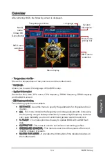
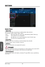
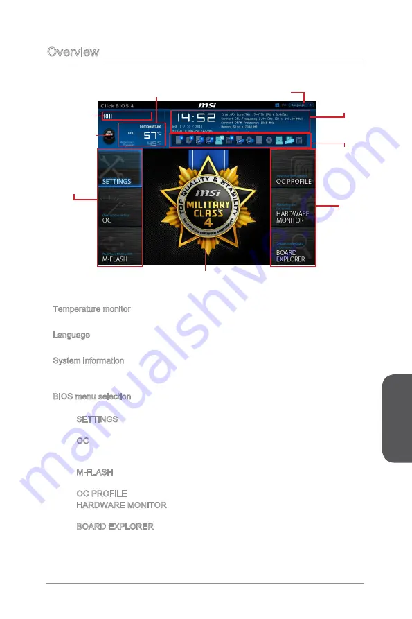
After entering BIOS, the following screen is displayed.

BIOS menu 

selection

Temperature monitor

System

information

Boot device 

priority bar

Menu display

BIOS menu 

selection

Language

Virtual OC 

Genie Button

Model 

name

Temperature monitor

Shows the temperatures of the processor and the motherboard.

Language

Allows you to select the language of the BIOS setup.

System information

Shows the time, date, CPU name, CPU frequency, DRAM frequency, DRAM capacity 

and the BIOS version.

BIOS menu selection

The following options are available:

SETTINGS - Uses this menu to specify the parameters for chipset and boot 

devices.

OC - This menu contains the frequency and voltage adjustments. Increasing 

the frequency can get better performance, however high frequency and heat 

can cause instability, we do not recommend general users to overclock. 

M-FLASH - This menu provides the way to update BIOS with a USB flash 

disk.

OC PROFILE -This menu is used to set various overclocking profiles.

HARDWARE MONITOR - This menu is used to set the speeds of fans and 

monitor voltages of system.

BOARD EXPLORER - It provides the information of the installed devices on 

the motherboard. 

Summary of Contents for H81I

Page 1: ...H81I H81I S01 Motherboard G52 78511XD Preface...

Page 2: ...s registered trademarks of Intel Corporation Windows is registered trademarks of Microsoft Corporation AMI is registered trademark of American Megatrends Inc Award is a registered trademark of Phoenix...

Page 3: ...within minutes Better yet the power calculator provides accurate estimates of power unit capacity for DIY users Technical Support If a problem arises with your system and no solution can be obtained f...

Page 4: ...Do not place anything over the power cord Always Unplug the Power Cord before inserting any add on card or module All cautions and warnings on the equipment should be noted Never pour any liquid into...

Page 5: ...hich can be determined by turning the equipment off and on the user is encouraged to try to correct the interference by one or more of the measures listed below Reorient or relocate the receiving ante...

Page 6: ...ent and its antenna must not be co located or operating in conjunction with any other antenna or transmitter European Community Compliance Statement The equipment complies with the RF Exposure Require...

Page 7: ...ld not be disposed of as unsorted household waste Please use the public collection system to return recycle or treat them in compliance with the local regulations Battery Information Chemical Substanc...

Page 8: ...ronik Altger te nicht mehr als kommunale Abf lle entsorgt werden MSI hat europaweit verschiedene Sammel und Recyclingunternehmen beauftragt die in die Europ ische Union in Verkehr gebrachten Produkte...

Page 9: ...de producten die de merknaam MSI dragen en verkocht zijn in de EU Deze goederen kunnen geretourneerd worden op lokale inzamelingspunten SRPSKI Da bi za titili prirodnu sredinu i kao preduze e koje vo...

Page 10: ...sb rn ch MAGYAR Annak rdek ben hogy k rnyezet nket megv dj k illetve k rnyezetv d k nt fell pve az MSI eml kezteti nt hogy Az Eur pai Uni EU 2005 augusztus 13 n hat lyba l p az elektromos s elektroni...

Page 11: ...Substances Information vii WEEE Waste Electrical and Electronic Equipment Statement viii Chapter 1 Getting Sarted 1 1 Packing Contents 1 2 Optional Accessories 1 2 Assembly Precautions 1 3 Motherboar...

Page 12: ...al Installer 1 26 Chapter 2 Quick Installation 2 1 CPU Installation 2 2 Memory Installation 2 4 Motherboard Installation 2 5 Power Connectors Installation 2 7 SATA HDD Installation 2 9 mSATA SSD Insta...

Page 13: ...Preface xiii Preface OC 3 14 M FLASH 3 19 OC PROFILE 3 20 HARDWARE MONITOR 3 21 Appendix A Realtek Audio A 1 Software Configuration A 2 Software panel overview A 2 Auto popup dialog A 3...

Page 14: ......

Page 15: ...ini ITX motherboard The the H81I H81I S01 series motherboards are based on Intel H81 chipset for optimal system efficiency Designed to fit the advanced Intel LGA1150 processor the the H81I H81I S01 se...

Page 16: ...ts may vary according to the model you purchased If you need to purchase the optional accessories or request part numbers please visit the MSI website at http www msi com index php or consult the deal...

Page 17: ...n handling the motherboard to prevent electrostatic damage If an ESD wrist strap is not available discharge yourself of static electricity by touching another metal object before handling the motherbo...

Page 18: ...1I only Storage Intel H81 Express Chipset 2x SATA 6Gb s ports SATA1 2 2x SATA 3Gb s ports SATA3 4 USB Intel H81 Express Chipset 2x USB 3 0 ports 2 ports available through the internal USB 3 0 connecto...

Page 19: ...are Monitor CPU System temperature detection CPU System fan speed detection CPU System fan speed control BIOS Features 64 Mb flash UEFI AMI BIOS ACPI 5 0 PnP 1 0a SM BIOS 2 7 DMI 2 0 Multi language Sp...

Page 20: ...hapter 1 1 6 Getting Started Connectors Quick Guide CPUFAN JFP1 PCI_E1 JFP2 JPWR1 SATA4 JPWR2 CPU Socket Back Panel JUSB3 DIMM2 DIMM1 SYSFAN1 JBAT1 JCOM1 JAUD1 JUSB1 SATA3 SATA2 SATA1 JUSB2 JTPM1 JCI1...

Page 21: ...s 1 15 JAUD1 Front Panel Audio Connector 1 24 JBAT1 Clear CMOS Jumper 1 25 JCI1 Chassis Intrusion Connector 1 21 JCOM1 Serial Port Connector 1 24 JFP1 JFP2 System Panel Connectors 1 22 JPWR1 2 ATX Pow...

Page 22: ...PDIF Out Line In Line Out Mic USB 3 0 Port LAN Port PS 2 Keyboard Mouse Combo Port USB 2 0 Port VGA Port HDMI DVI D Port H81I Line In Line Out Mic USB 2 0 Port LAN Port PS 2 Keyboard Mouse Combo Port...

Page 23: ...s manual for more information HDMI Port For H81I The High Definition Multimedia Interface HDMI is an all digital audio video interface that is capable of transmitting uncompressed streams HDMI support...

Page 24: ...vity LED Off No link Yellow Linked Blinking Data activity Speed LED Off 10 Mbps connection Green 100 Mbps connection Orange 1 Gbps connection Audio Ports These connectors are used for audio devices Th...

Page 25: ...s power cord to ensure the safety of the CPU Overclocking This motherboard is designed to support overclocking Before attempting to overclock please make sure that all other system components can tol...

Page 26: ...ation Wrong installation can damage both the CPU and the motherboard 1 Push the load lever down to unclip it and lift to the fully open position 2 The load plate will automatically lift up as the load...

Page 27: ...under the retention knob Close and engage the load lever Alignment Key CPU notches Retention knob 5 When you press down the load lever the PnP cap will automatically pop up from the CPU socket Do not...

Page 28: ...CPU fan connector on the motherboard 8 Place the heatsink on the motherboard with the fan s cable facing towards the fan connector and the fasteners matching the holes on the motherboard CPU fan conne...

Page 29: ...ve data with two data bus channels simultaneously Enabling Dual Channel mode can enhance system performance The following illustrations explain the population rules for Dual Channel mode DIMM1 DIMM2 I...

Page 30: ...cure the motherboard with the screws provided with your computer case The locations of the screw holes on the motherboard are shown below For more information please refer to the manual that came with...

Page 31: ...If done correctly the clip on the power cable should be hooked on the motherboard s power connector 4 1 2 V 2 G r o u n d 3 1 2 V 1 G r o u n d 1 3 3 3 V 1 3 3 V 1 4 1 2 V 2 3 3 V 1 5 G r o u n d 3 G...

Page 32: ...pports the PCIe interface expansion card Important When adding or removing expansion cards always turn off the power supply and unplug the power supply power cable from the power outlet Read the expan...

Page 33: ...o Card Installation Determine what type of expansion slot s the video card will use Locate the expansion slot s on the motherboard Remove any protective expansion slot covers from the computer case Li...

Page 34: ...e from the power supply Such devices include disk drives HDD solid state drives SSD and optical drives CD DVD Blu Ray Please refer to the device s manual for further information Many computer cases al...

Page 35: ...r consult your vendor to find recommended CPU heatsink These connectors support Smart Fan Control with liner mode The Command Center utility can be installed to automatically control the fan speeds ac...

Page 36: ...herboard Video Demonstration Watch the video to learn how to Install front panel connectors http youtu be DPELIdVNZUI 3 S p e a k e r 4 V C C 5 1 S p e a k e r 2 V C C 5 JFP2 1 3 1 0 N o P i n 5 R e s...

Page 37: ...kwards compatible with USB 2 0 devices It supports data transfer rates up to 5Gbits s SuperSpeed 5 U S B 3 _ T X _ C _ D N 4 G r o u n d 3 U S B 3 _ R X _ D P 2 U S B 3 _ R X _ D N 1 P o w e r 1 0 G r...

Page 38: ...Guide 1 M I C L 3 M I C R 1 0 H e a d P h o n e D e t e c t i o n 5 H e a d P h o n e R 7 S E N S E _ S E N D 9 H e a d P h o n e L 8 N o P i n 6 M I C D e t e c t i o n 4 N C 2 G r o u n d JCOM1 Seri...

Page 39: ...d r e s s d a t a p i n 2 1 1 L P C a d d r e s s d a t a p i n 3 1 3 L P C F r a m e Jumper JBAT1 Clear CMOS Jumper There is CMOS RAM onboard that is external powered from a battery located on the m...

Page 40: ...ve utilities Total Installer Total Installer is very easy to use and does a great job of finding necessary drivers Please follow the steps below to install drivers and utilities for your new computer...

Page 41: ...er Some of the installations also provide video demonstrations Please link to the URL to watch it with the web browser on your phone or tablet You may have even link to the URL by scanning the QR code...

Page 42: ...Chapter 2 2 2 Quick Installation CPU Installation 1 2 3 4 5 6 http youtu be bf5La099urI...

Page 43: ...Chapter 2 2 3 Quick Installation 7 8 9...

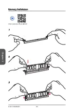
Page 44: ...Chapter 2 2 4 Quick Installation Memory Installation 1 2 3 http youtu be 76yLtJaKlCQ...

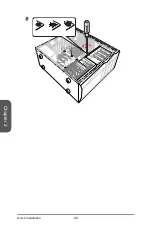
Page 45: ...Chapter 2 2 5 Quick Installation Motherboard Installation 1 2...

Page 46: ...Chapter 2 2 6 Quick Installation 3...

Page 47: ...7 Quick Installation Power Connectors Installation E6 88 MSI MC4 E6 88 MSI MC4 E6 88 MSI MC4 E6 88 MSI MC4 E6 88 MSI MC4 E6 88 MSI MC4 E6 88 MSI MC4 E6 88 MSI MC4 E6 88 MSI MC4 or 1 2 http youtu be g...

Page 48: ...hapter 2 2 8 Quick Installation E6 88 MSI MC4 E6 88 MSI MC4 E6 88 MSI MC4 E6 88 MSI MC4 E6 88 MSI MC4 E6 88 MSI MC4 E6 88 MSI MC4 E6 88 MSI MC4 E6 88 MSI MC4 E6 88 MSI MC4 E6 88 MSI MC4 E6 88 MSI MC4...

Page 49: ...outu be RZsMpqxythc E6 88 MS I MC 4 E68 8 MSI MC4 E68 8 MSI MC4 E68 8 MSI MC4 E68 8 MSI MC4 E6 88 MS I MC 4 E6 88 MS I MC 4 E6 88 MS I MC 4 E6 88 MS I MC 4 E68 8 MSI MC4 E68 8 MSI MC4 E68 8 MSI MC4 E6...

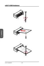
Page 50: ...Chapter 2 2 10 Quick Installation mSATA SSD Installation...

Page 51: ...MC4 E68 8 MSI MC4 E68 8 MSI MC4 E68 8 MSI MC4 E6 88 MS I MC 4 E6 88 MS I MC 4 E6 88 MS I MC 4 HD_LED HD_LED RST_SW RST_SW RSVD_DNU HD_LED HD_LED RST_SW RST_SW RSVD_DNU PWR_SW PWR_SW FP PWR SLP FP PWR...

Page 52: ...MSI MC4 USB E6 88 MSI MC4 E68 8 MSI MC4 E68 8 MSI MC4 E68 8 MSI MC4 E68 8 MSI MC4 E68 8 MSI MC4 E68 8 MSI MC4 E68 8 MSI MC4 E68 8 MSI MC4 E6 88 MSI MC4 USB E6 88 MSI MC4 E68 8 MSI MC4 E68 8 MSI MC4 E...

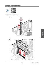
Page 53: ...Chapter 2 2 13 Quick Installation Graphics Card Installation http youtu be mG0GZpr9w_A 1 2...

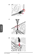
Page 54: ...Chapter 2 2 14 Quick Installation 3 4 5...

Page 55: ...re the default settings if the system becomes unbootable after changing BIOS settings Refer to the Clear CMOS jumper button section to clear the CMOS data select the Restore Defaults and press Enter i...

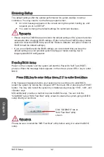
Page 56: ...to avoid possible system damage or failure booting due to inappropriate BIOS configuration Entering BIOS Setup Power on the computer and the system will start the Power On Self Test POST process When...

Page 57: ...d the BIOS version BIOS menu selection The following options are available SETTINGS Uses this menu to specify the parameters for chipset and boot devices OC This menu contains the frequency and voltag...

Page 58: ...be light Enabling OC Genie function can automatically overclock with MSI optimized overclocking profile Model Name Shows the model name of motherboard Sub Menu General Help Sub menu If you find a poi...

Page 59: ...ick Double click the left button Select Icon Field Esc Click the right button Jump to the Exit menu or return to the previous from a submenu Increase the numeric value or make changes Decrease the num...

Page 60: ...d by numeric function keys year The year can be adjusted by users System Time Sets the system time Use tab key to switch between time elements The time format is hour minute second SATA Port Shows the...

Page 61: ...3 state Blinking The power LED blinks to indicate the S3 state Integrated Peripherals Sets integrated peripherals parameters such as LAN HDD USB and audio Press Enter to enter the sub menu Onboard LAN...

Page 62: ...abled Disables hot plug support for the SATA ports HD Audio Controller Enabled Enables or disables the onboard High Definition Audio controller HPET Enabled The HPET High Precision Event Timers is a c...

Page 63: ...tem will automatically detect if any USB device is connected and enables or disables the legacy USB support Enabled Enable the USB support for legacy operating systems that do not support USB Disabled...

Page 64: ...es for other operating systems Before enabling this item make sure all installed devices utilities hardware software should meet the Windows 8 requirements Enabled The system will switch to UEFI mode...

Page 65: ...nd manually load the secure keys Image Execution Policy Sets the policy when the system image execution policy on Security Violation Press Enter to enter the sub menu This sub menu will appear when Se...

Page 66: ...d Disabled Disables or enables the system wake up by PS 2 keyboard Any Key Enables the system to be awakened from S3 S4 S5 state when activity of any key on PS 2 keyboard is detected Hot Key Enables t...

Page 67: ...assword is being disabled Once the password is disabled you can enter the setup and OS without authorization U Key Disabled Enables or disables U Key as user s password to access the system Make U Key...

Page 68: ...g Read only Adjust CPU Ratio Auto Sets the CPU ratio that is used to determine CPU clock speed This item can only be changed if the processor supports this function Adjusted CPU Frequency Shows the ad...

Page 69: ...re the DRAM timing manually for all memory channel UnLink Allows user to configure the DRAM timing manually for respective memory channel Advanced DRAM Configuration Press Enter to enter the sub menu...

Page 70: ...r Threading technology treats the multi cores inside the processor as multi logical processors that can execute instructions simultaneously In this way the system performance is highly improved Enable...

Page 71: ...ables the requested cache line only CPU AES Instructions Enabled Enables or disables the CPU AES Advanced Encryption Standard New Instructions support This item appears when a CPU supports this functi...

Page 72: ...ote The following items will appear when Intel Turbo Boost is enabled Long Duration Power Limit W Auto Sets the long duration TDP power limit for CPU in Turbo Boost mode Long Duration Maintained s Aut...

Page 73: ...ers Select one file to boot Selects a BIOS file in the USB flash disk NTFS FAT 32 format to boot the system This item will selectable when the BIOS Boot function is enabled Save BIOS to storage Saves...

Page 74: ...Profile 1 2 3 4 5 6 Saves the current overclocking profile Load Overclocking Profile 1 2 3 4 5 6 Loads the current overclocking profile Clear Overclocking Profile 1 2 3 4 5 6 Clears the current overc...

Page 75: ...t CPU system temperature The green shows current CPU System fan speed Fan control field This motherboard provides a fan speed control feature call Smart Fan Control Smart Fan Control automatically con...

Page 76: ...rrow symbol to set the minimum fan speed in percentage e Slides the arrow symbol to set the maximum fan speed in percentage f Click the Default button to restore the default values Or click the Cancel...

Page 77: ...udio The Realtek audio provides 10 channel DAC that simultaneously supports 7 1 sound playback and 2 channels of independent stereo sound output multiple streaming through the Front Out Left and Front...

Page 78: ...ght of the screen You may double click the icon and the GUI will pop up accordingly double click the icon It is also available to enable the audio driver by clicking the Realtek HD Audio Manager from...

Page 79: ...just the bar Application Enhancement The array of options will provide you a complete guidance of anticipated sound effect for both output and input device Jack status panel This panel depicts all ren...

Page 80: ......

Reviews: