background image

B-18


MS-7135 ATX  Mainboard

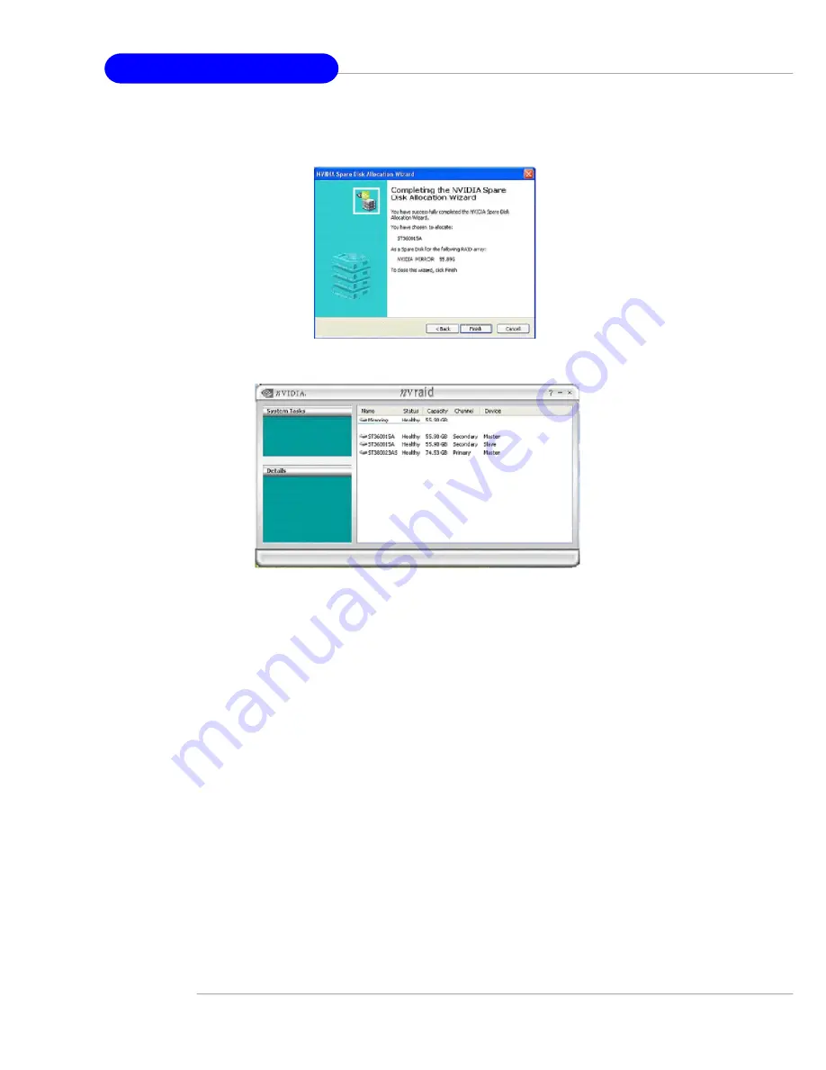
5.


Click 

Next

. The Completing the NVIDIA Spare Disk Allocation page appears.

6.


Click 

Finish

.

You have now assigned a  dedicated free disk to a mirrored array.

Once a dedicated disk has been assigned to a particular array, it can be removed at
any time. To remove the disk, right click on the dedicated disk and select the option to
remove it.

Summary of Contents for K8N Neo3 MS-7135

Page 1: ...i MS 7135 v1 X ATX Mainboard English Version G52 M7135X4 K8N Neo3 Series ...

Page 2: ...ent in a residential area is likely to cause harmful interference in which case the user will be required to correct the interference at his own expense Notice 1 The changes or modifications not expressly approved by the party responsible for compliance could void the user s authority to operate the equipment Notice 2 Shielded interface cables and A C power cord if any must be used in order to com...

Page 3: ...8 2000 NT XP are registered trademarks of Microsoft Corporation NVIDIA the NVIDIA logo DualNet and nForce are registered trademarks or trade marks of NVIDIA Corporation in the United States and or other countries Netware is a registered trademark of Novell Inc Award is a registered trademark of Phoenix Technologies Ltd AMI is a registered trademark of American Megatrends Inc Revision History Revis...

Page 4: ...n card or module 9 All cautions and warnings on the equipment should be noted 10 Never pour any liquid into the opening that could damage or cause electrical shock 11 If any of the following situations arises get the equipment checked by a service personnel The power cord or plug is damaged Liquid has penetrated into the equipment The equipment has been exposed to moisture The equipment has not wo...

Page 5: ...PU Installation Procedures for Socket 754 2 4 Installing AMD Athlon64 CPU Cooler Set 2 5 Memory 2 7 Memory Population Rules 2 7 Installing DDR Modules 2 8 Power Supply 2 9 ATX 24 Pin Power Connector JWR1 2 9 ATX 12V Power Connector JPW1 2 9 Important Notification about Power Issue 2 10 Back Panel 2 11 Connectors 2 12 Floppy Disk Drive Connector FDD1 2 12 Fan Power Connectors CFAN1 SFAN1 NBFAN1 2 1...

Page 6: ...3 The Main Menu 3 4 Standard CMOS Features 3 6 Advanced BIOS Features 3 8 Advanced Chipset Features 3 11 Integrated Peripherals 3 12 Power Management Setup 3 17 PNP PCI Configurations 3 20 H W Monitor 3 22 Cell Menu 3 24 Load Fail Safe Optimized Defaults 3 30 BIOS Setting Password 3 31 Chapter 4 Introduction to DigiCell 4 1 Main 4 2 Introduction 4 2 H W Diagnostic 4 4 Communication 4 5 Software Ac...

Page 7: ... Function A 12 Appendix B nVIDIA RAID Introduction B 1 Introduction B 2 System Requirement B 2 RAID Arrays B 2 Summary of RAID Configurations B 3 Basic Configuration Instructions B 3 Setting Up theNVRAID BIOS B 3 RAID Configuration B 3 Installing the NVIDIA RAID Software Under Windows B 7 NVIDIA RAID Utility Installation B 7 Installing the RAID Driver for bootable RAID Array B 8 Initializing and U...

Page 8: ...ng the K8N Neo3 MS 7135 v1 X ATX mainboard The K8N Neo3 mainboard is based on nVIDIA nForce4 4X chipset for optimal system efficiency Designed to fit the advanced AMD K8 Athlon 64 processor the K8N Neo3 mainboard delivers a high performance and professional desktop platform solution ...

Page 9: ...m tw program products mainboard mbd pro_mbd_trp_list php Slots One PCI Express x16 slot PCI Express Bus specification v1 0a compliant One PCI Express x1 slot PCI Express Bus specification v1 0a compliant Three 32 bit Master 3 3V 5V PCI Bus slots One AGR Advance Graphics Riser slot for compatible AGP VGA cards For more detailed information on compatible AGP VGA cards please refer to http www msi co...

Page 10: ...pherals include 1 floppy port supports 1 FDD with 360K 720K 1 2M 1 44M and 2 88Mbytes 2 serial ports 1 parallel port supporting SPP EPP ECP mode 10 USB2 0 ports Rear 4 Front 6 1 Audio Line In Line Out MIC port 1 RJ 45 LAN jack 1 CD In pinheader 2 IDE ports support 4 IDE devices 4 serial ATA ports BIOS The mainboard BIOS provides Plug Play BIOS which detects the peripheral devices and expansion car...

Page 11: ...ATX Mainboard Dimension ATX form factor 300mm x 185mm Mounting 6 mounting holes MSI Reminds You Please note that the companion MSI Driver Utility CD supports this mainboard with Windows 2000 XP system drivers ONLY ...

Page 12: ...ATA1 SATA2 SATA3 SATA4 J1 T LAN Jack B USB Ports Winbond W83627THF LAN BATT DIMM 1 CFAN1 DIMM 2 JWR1 PCI 3 PCI 2 PCI 1 PCI_E1 PCI_E2 IDE 2 IDE 1 JFP1 JUSB1 JUSB2 JUSB3 JFP2 JCI1 JAUD1 Top Parallel Port Bottom COM Port Top Mouse Bottom Keyboard BIOS Codec USB Ports Line In Line Out Mic JCOM1 AGR nVIDIA nForce4 4X ...

Page 13: ...kbar and the following dialog box will appear You can specify how often the system will automatically search for the BIOS drivers version or change the LAN settings right from the dialog box You can right click the MSI Live Monitor icon to perform the functions listed below l Auto Search Searches for the BIOS drivers version you need immediately l View Last Result Allows you to view the last searc...

Page 14: ...I Live Update 3 icon and the fol lowing screen will appear Several buttons are placed on the left column of the screen Click the desired button to start the update process ö Live BIOS Updates the BIOS online ö Live Driver Updates the drivers online ö Live VGA BIOS Updates the VGA BIOS online ö Live VGA Driver Updates the VGA driver online ö Live Utility Updates the utilities online If the product ...

Page 15: ...en the CPU temperature climbs up to a certain degree the speed of the system cooling fan will be risen automatically On the other hand the speed of the system cooling fan will slow down instantly when the CPU temperature descends to its normal degree Here the current system status including Vcore 3 3V 5V and 12V and the current PC hardware status such as the CPU system temperatures and all fans sp...

Page 16: ...ystem temperatures and fan speeds You may use the scroll bars to adjust each item then click OK to apply the changes The values you set for the temperatures are the maximum thresholds for the system warnings and the values for fan speeds are the minimum thresholds Center side Cool n Quiet User mode Here you may adjust the CPU fan speed If you choose User mode you may adjust the CPU fan speed in 8 ...

Page 17: ...rd Packing Checklist Power Cable SATA Cable Optional MSI Driver Utility CD RAID Driver Disk Round Cable of IDE Devices Optional Back IO Shield Round Cable of Floppy Disk Optional USB Bracket Optional User s Guide MSI mainboard ...

Page 18: ...ules and expansion cards as well as how to setup the jumpers on the mainboard Also it provides the instructions on connecting the pe ripheral devices such as the mouse keyboard etc While doing the installation be careful in holding the compo nents and follow the installation procedures Hardware Setup ...

Page 19: ...anel I O p 2 11 JPW1 p 2 9 IDE1 2 p 2 13 JWR1 p 2 9 CFAN1 p 2 12 FDD1 p 2 12 JFP2 p 2 16 PCI Express Slots p 2 19 PCI Slots p 2 19 JAUD1 p 2 15 J1 p 2 15 JFP1 p 2 16 JCI1 p 2 17 JUSB1 2 3 p 2 17 SATA1 4 p 2 14 SW_BAT1 p 2 18 JCOM1 p 2 16 CPU p 2 3 NBFAN1 SFAN1 p 2 12 AGR Slot p 2 20 ...

Page 20: ...bd_cpu_support php MSI Reminds You Overheating Overheating will seriously damage the CPU and system always make sure the cooling fan can work properly to protect the CPU from overheating Replacing the CPU While replacing the CPU always turn off the ATX power supply or unplug the power supply s power cord from grounded outlet first to ensure the safety of CPU Overclocking This motherboard is design...

Page 21: ...s should be completely embedded into the socket and can not be seen Please note that any violation of the correct installation procedures may cause permanent damages to your mainboard 5 Press the CPU down firmly into the socket and close the lever As the CPU is likely to move while the lever is being closed al ways close the lever with your fingers pressing tightly on top of the CPU to make sure t...

Page 22: ...plate s paster 2 Turn over the mainboard and install the backplate to the proper position 3 Turn over the mainboard again and place the mainboard on the flat surface Locate the two screw holes of the mainboard 4 Align the retention mechanism and the backplate Fix the retention mechanism and the backplate with two screws MSI Reminds You Mainboard photos shown in this section are for demonstration o...

Page 23: ... on the top of the retention mechanism 8 Make sure the safety hook completely clasps the fixed bolt of the retention mechanism 9 Attach the CPU Fan cable to the CPU fan connector on the mainboard 7 Fasten down the lever MSI Reminds You While disconnecting the Safety Hook from the fixed bolt it is neces sary to keep an eye on your fingers because once the Safety Hook is disconnected from the fixed ...

Page 24: ...M slot supports up to a maximum size of 1GB Users can install either single or double sided modules to meet their own needs Memory modules can be installed in any combination as follows S Single Side D Double Side Slot Memory Module TotalMemory DIMM 1 S D 64MB 1GB DIMM 2 S D 64MB 1GB Maximum System Memory Supported 64MB 2GB MSI Reminds You 1 Make sure that you install memory modules of the same ty...

Page 25: ...tation 2 Insert the DIMM memory module vertically into the DIMM slot Then push it in until the golden finger on the memory module is deeply inserted in the socket 3 The plastic clip at each side of the DIMM slot will automatically close Volt Notch MSI Reminds You You can barely see the golden finger if the module is properly inserted into the socket ...

Page 26: ...re the plug of the power supply is inserted in the proper orientation and the pins are aligned Then push down the power supply firmly into the connector You may use the 20 pin ATX power supply as you like If you d like to use the 20 pin ATX power supply please plug your power supply along with pin 1 pin 13 refer to the image at the right hand There is also a foolproof design on pin 11 12 23 24 to ...

Page 27: ...cement actions might cause chipset system unable to boot Please follow the following solution to avoid this situation Unplug the AC power cable shown in figure 1 or unplug the JWR1 JPW1 power connectors shown in figure 2 figure 3 before the 1st installation or during system upgrade procedure MSI Reminds You Mainboard photos shown in this section are for demonstration only The appearance of your ma...

Page 28: ...fferential Pair3 8 D3N Differential Pair 3 10 100 LAN Optional PIN SIGNAL DESCRIPTION 1 TDP Transmit Differential Pair 2 TDN Transmit Differential Pair 3 RDP Receive Differential Pair 4 NC Not Used 5 NC Not Used 6 RDN Receive Differential Pair 7 NC Not Used 8 NC Not Used Serial Port PIN SIGNAL 1 DCD 2 SIN 3 SOUT 4 DTR 5 GND 6 DSR 7 RTS 8 CTS 9 RI 1 2 3 4 5 6 7 8 9 USB Ports 1 2 3 4 PIN SIGNAL 1 VC...

Page 29: ... and should be connected to GND If the mainboard has a System Hardware Monitor chipset onboard you must use a specially designed fan with speed sensor to take advantage of the CPU fan control MSI Reminds You 1 Always consult the vendors for proper CPU cooling fan 2 CFAN1 supports Smart Fan control You can install Core Center utility that will automatically control the CPU fan speed according to th...

Page 30: ...he hard disk docu mentation supplied by hard disk vendors for jumper setting instructions ATA133 Hard Disk Connectors IDE1 IDE2 The mainboard has a 32 bit Enhanced PCI IDE and Ultra DMA 66 100 133 con troller that provides PIO mode 0 4 Bus Master and Ultra DMA 66 100 133 function You can connect up to four hard disk drives CD ROM and other IDE devices The Ultra ATA133 interface boosts data transfe...

Page 31: ...erial ATA Connectors SATA1 SATA4 SATA1 SATA4 are high speed Serial ATA interface ports Each supports 1st generation serial ATA data rates of 150MB s and is fully compliant with Serial ATA 1 0 specifications Each Serial ATA connector can connect to 1 hard disk device MSI Reminds You Please do not fold the Serial ATA cable into 90 degree angle Otherwise data loss may occur during transmission 7 1 SA...

Page 32: ...onnectivity Design Guide JAUD1 1 2 9 10 PIN SIGNAL DESCRIPTION 1 AUD_MIC Front panelmicrophone input signal 2 AUD_GND Ground usedbyanalog audio circuits 3 AUD_MIC_BIAS Microphonepower 4 AUD_VCC Filtered 5V used by analog audio circuits 5 AUD_FPOUT_R Right channel audio signal to front panel 6 AUD_RET_R Right channel audio signal return from front panel 7 HP_ON Reserved forfuture useto control head...

Page 33: ...rSwitch lowreferencepull down to GND 9 RSVD_DNU Reserved Donot use JFP1 Pin Definition Serial Port Header JCOM1 The mainboard offers one 9 pin header as serial port The port is a 16550A high speed communication port that sends receives 16 bytes FIFOs You can attach a serial mouse or other serial device directly to it Pin Definition PIN SIGNAL DESCRIPTION 1 DCD Data Carry Detect 2 SIN Serial In orR...

Page 34: ...SIGNAL 1 VCC 2 VCC 3 USB0 4 USB1 5 USB0 6 USB1 7 GND 8 GND 9 Key no pin 10 USBOC Pin Definition MSI Reminds You Note that the pins of VCC and GND must be connected correctly to avoid possible damage Connect to JUSB1 JUSB2 or JUSB3 USB 2 0 Bracket Optional Chassis Intrusion Switch Connector JCI1 This connector is connected to a 2 pin chassis switch If the chassis is opened the switch will be short ...

Page 35: ... spe cifically referred to as CMOS RAM It is a tiny 64 byte region of memory that owing to battery power retains system configuration data when the PC is shut off With the CMOS RAM the system can automatically boot OS every time it is turned on If you want to clear the system configuration press the SW_BAT1 button to have the data erased Jumpers Buttons MSI Reminds You You can clear CMOS by pressi...

Page 36: ...ktop platforms with PCI Express Architecture will be designed to deliver highest performance in video graphics multimedia and other sophisticated applications Moreover PCI Express architecture provides a high performance graphics infrastructure for Desktop Platforms doubling the capability of existing AGP 8x de signs with transfer rates of 4 0 GB s over a PCI Express x16 lane for graphics controll...

Page 37: ...ssor 2800 FSB 200 Memory Transcend SEC K4H280838D TCB3 DDR333 256MB VGA Card As Follows Lan Card Onboard Sound Card Onboard Hard Drive Hitachi HDS7222580VLSA80 SATA150 82 3GB CD ROM BenQ CD652A 52X Floppy Drive TEAC FD 235HF 1 44MB Power Supply DELTA DPS 300KB 1A 300W Mouse Acer M S69 PS 2 Keyboard Acer 6511 CX PS 2 Device Configuration Monitor ViewSonic P225f 22 CRT VGA BIOS VGA Driver MB Driver ...

Page 38: ...008 000 4X Pass 6 14 10 6453 24 ATI Radeon LE Radeon LE DDR 32MB DDR SGRAM P N113 10604 100 4X Pass 6 13 10 6153 25 ATI Fire GL 8700 Fire GL 8700 64MB DDR SDRAM 1 11 4X Pass 6 12 10 3051 26 ATI Radeon 9000 Pro Radeon DDR 64MB DDR SDRAM BK8 0 0 4X Pass 6 14 10 6458 27 ATI Radeon 9500 Radeon 9500 64MB DDR SDRAM 113 94210 100 8X Pass 6 14 10 6458 28 ATI Radeon 9700 Radeon 9700 128MB DDR SDRAM 113 942...

Page 39: ... 18 20 02 21 8X Pass 6 6 8 1 55 MSI MS 8894 GeForce 4 Ti 4200 128MB DDR SDRAM 4 28 20 05 11 8X Pass 6 6 8 1 56 MSI MS 8895 GeForce 4 MX 440 64MB DDR SDRAM 4 18 2007 8X Pass 6 6 8 1 57 MSI MS 8900 GeForce 4 Ti 4800 SE 128MB DDR SDRAM 4 28 20 21 00 8X Pass 6 6 8 1 58 MSI MS 8904 GeForce FX 5800 128MB DDR SDRAM 4 30 20 23 05 8X Pass 6 6 8 1 59 MSI MS 8948 GeForce FX 5700 128MB DDR SDRAM 4 36 20 19 06...

Page 40: ...in this chapter are under continuous update for better system performance Therefore the description may be slightly different from the lat est BIOS and should be held for reference only 2 Upon boot up the 1st line appearing after the memory count is the BIOS version It is usually in the format W7135NMS V1 0 150304 where 1st digit refers to BIOS maker as A AMI W AWARD and P PHOENIX 2nd 5th digit re...

Page 41: ...art the system by simultaneously pressing Ctrl Alt and Delete keys Control Keys Move to the previous item Move to the next item Move to the item in the left hand Move to the item in the right hand Enter Select the item Esc Jumps to the Exit menu or returns to the main menu from a submenu PU Increase the numeric value or make changes PD Decrease the numeric value or make changes F1 General help onl...

Page 42: ...t of certain fields that means a sub menu con taining additional options can be launched from this field You can use control keys to highlight the field and press Enter to call up the sub menu Then you can use the control keys to enter values and move from field to field within a sub menu If you want to return to the main menu just press Esc General Help F1 The BIOS setup program provides a Genera...

Page 43: ... Peripherals Use this menu to specify your settings for integrated peripherals Power Management Setup Use this menu to specify your settings for power management PNP PCI Configurations This entry appears if your system supports PnP PCI H W Monitor This entry shows your PC health status Once you enter Phoenix Award BIOS CMOS Setup Utility the Main Menu will appear on the screen The Main Menu allows...

Page 44: ...ad Optimized Defaults Use this menu to load the default values set by the mainboard manufacturer specifi cally for optimal performance of the mainboard BIOS Setting Password Use this menu to set the password for BIOS Save Exit Setup Save changes to CMOS and exit setup Exit Without Saving Abandon all changes and exit setup ...

Page 45: ... PgUp or PgDn to select Manual None or Auto type Note that the specifications of your drive must match with the drive table The hard disk will not work properly if you enter improper information for this category If your hard disk drive type is not matched or listed you can use Manual to define your own drive type manually If you select Manual related information is asked to be entered to the foll...

Page 46: ...720K 3 5 in 1 44M 3 5 in 2 88M 3 5 in Halt On The setting determines whether the system will stop if an error is detected at boot Available options are All Errors The system stops when any error is detected No Errors The system doesn t stop for any detected error All But Keyboard The system doesn t stop for a keyboard error All But Diskette The system doesn t stop for a disk error All But Disk Key...

Page 47: ... the OS 2 operating system with DRAM larger than 64MB Settings Yes No IOAPIC Function This field is used to enable or disable the APIC Advanced Programmable Interrupt Controller Due to compliance with PC2001 design guide the system is able to run in APIC mode Enabling APIC mode will expand available IRQ resources for the system Settings Enabled and Disabled MPS Table Version This field allows you ...

Page 48: ...the option to Enabled allows the system to try to boot from other device if the system fails to boot from the 1st 2nd 3rd boot device Hard Disk Boot Priority Press Enter to enter the sub menu Then you may use the arrow keys to select the desired device and press or PageUp PageDown key to move it up down in this hard disk boot priority list MSI Reminds You Available settings for 1st 2nd 3rd Boot De...

Page 49: ...ou are familiar with the chipset It is strongly recommended that users should leave the settings to their default options DRAM Configuration Press Enter to enter the sub menu and the following screen appears Timing Mode This field has the capacity to automatically detect all of the DRAM timing If you ...

Page 50: ...ress strobe to CAS column address strobe The less the clock cycles the faster the DRAM performance Setting options Auto 2T 7T Row Precharge Time Trp When the Timing Mode is set to Manual the field is adjustable This item controls the number of cycles for Row Address Strobe RAS to be allowed to precharge If insufficient time is allowed for the RAS to accumulate its charge before DRAM refresh refres...

Page 51: ...t to Manual the field is adjustable This item controls the Write Data In to Read Command Delay memory timing This consti tutes the minimum number of clock cycles that must occur between the last valid write operation and the next read command to the same internal bank of the DDR device Available settings Auto 1T 2T Read to Write delay Trwt When the Timing Mode is set to Manual the field is adjusta...

Page 52: ...ad The controller will disable its DQS receiver until the read preamble time and then enable its DQS receiver while the DRAM asserts DQS Setting options 2ns 9 5ns Async Latency value When the User Config mode is set to Manual the field is adjustable This field should be loaded with 4 bit value equal to th e maximum asynchronous latency in the DRAM read round trip loop Setting options 2ns 11ns MTRR...

Page 53: ...abled Disabled Onboard LAN Controller Setting to Auto allows the BIOS to auto detect the nVIDIA LAN controller and enable it Setting options Auto and Disabled Onboard LAN Option ROM This item is used to enable or disable the MAC LAN Boot ROM Setting options Disabled Enabled AC97 Controller Auto allows the mainboard to detect whether an audio device is used If an audio device is detected the onboar...

Page 54: ...s a built in parallel port on the on board Super I O chipset that provides Standard ECP and EPP features It has the following options Disabled 3BC IRQ7 Line Printer port 0 278 IRQ5 Line Printer port 2 378 IRQ7 Line Printer port 1UART Mode Select Parallel Port Mode SPP Standard Parallel Port EPP Enhanced Parallel Port ECP Extended Capability Port ECP EPP Extended Capability Port Enhanced Parallel P...

Page 55: ...ssage will appear ECP Mode Use DMA At this time the user can choose between DMA channel 3 or 1 IDE Device Configuration Press Enter to enter the sub menu and the following screen appears OnChip IDE Channel 0 1 The integrated peripheral controller contains an IDE interface with support for two IDE channels Choose Enabled to activate each channel separately Settings Enabled Disabled IDE DMA Transfer...

Page 56: ...ed the following fields will become selectable Setting options Enabled Disabled IDE Primary Secondary Master Slave RAID This feature allows users to enable or disable the RAID function for each IDE hard disk drive Settings Enabled Disabled SATA1 SATA2 SATA3 SATA4 RAID This feature allows users to enable or disable the RAID function for each onchip SATA hard disk drive The settings are Enabled Disa...

Page 57: ...lost CPU or chipset and hard ware maintains all system context S3 STR The S3 sleep mode is a lower power state where the in formation of system configuration and open appli cations files is saved to main memory that remains powered while most other hardware components turn off to save energy The information stored in memory will be used to restore the system when a wake up event occurs Video Off M...

Page 58: ...aves the computer in the power on state Former Sts Restores the system to the status before power failure or interrupt occurred Wake Up Event Setup Press Enter and the following sub menu appears Resume S3 By PS 2 Keyboard Resume S3 By PS 2 Mouse These fields allow the activity of the PS 2 peripherals keyboard and mouse to wake up the system from S3 sleep state Settings Enabled Disabled Resume By P...

Page 59: ...setting you must let the system boot up until it enters the operating system before this function will work Date The field specifies the date for Resume By RTC Alarm Settings 0 31 HH MM SS The field specifies the time for Resume By RTC Alarm Format is hour minute second ...

Page 60: ...BIOS has the capacity to automatically configure all of the boot and Plug and Play compatible devices However this capability means abso lutely nothing unless you are using a Plug and Play operating system such as Win dows 95 98 If you set this field to manual choose specific resources by going into each of the sub menu that follows this field a sub menu is preceded by a Ø Setting options Auto ESC...

Page 61: ...S 7135 ATX Mainboard PCI Express Relative Items Maximum Payload Size This setting specifies the maximum TLP payload size for the PCI Express devices The unit is byte Setting options 128 256 512 1024 2048 4096 ...

Page 62: ...atus and issuing a warning message if the chassis is once opened To clear the warning message set the field to Reset The setting of the field will automatically return to Enabled later Setting options Enabled Reset Disabled Smart CPU Fan Target The BIOS povides the Smart Fan system which can control the fan speed automati cally depending on the current temperature to keep it within a specific rang...

Page 63: ...t System CPU Temperature System CPU Northbridge Fan Speed CPU Vcore 3 3V 5 0V Battery 5VSB These items display the current status of all of the monitored hardware de vices components such as CPU voltage temperatures and all fans speeds ...

Page 64: ...horten to increase the performance Setting options Enabled Disabled Dynamic Overclocking Dynamic Overclocking Technology is the automatic overclocking function included in the MSITM s newly developed CoreCellTM Technology It is designed to detect the load balance of CPU while running programs and to adjust the best CPU frequency automatically When the motherboard detects CPU is running programs it...

Page 65: ...ans Chip to CPU HT Width And mark means CPU to Chip HT Width Setting options 8 8 16 8 8 16 16 16 CPU Spread Spectrum This setting is used to enable or disable the CPU Spread Spectrum feature When overclocking the CPU always set it to Disabled Setting options Center Spread Disabled SATA Spread Spectrum This setting is used to enable or disable the SATA Spread Spectrum feature Setting options Disabl...

Page 66: ...ecision floating point values and on integer values Several of these new SSE SSE2 instructions also operate in the MMX registers Cool n Quiet This feature is especially designed for AMD Athlon processor which provides a CPU temperature detecting function to prevent your CPU s from overheating due to heavy workload Setting options Disabled Enabled Adjust CPU Ratio This item lets you adjust the CPU ...

Page 67: ...for your system Gray Default setting Yellow High performance setting Red Not recommended setting and the system may be unstable Changing CPU Voltage Memory Voltage and NF4 Voltage may result in the instability of the system therefore it is NOT recom mended to change the default setting for long term usage NF4 Voltage NF4 voltage is adjustable in this field ...

Page 68: ...nter The password typed now will replace any previously set password from CMOS memory You will be prompted to confirm the password Retype the password and press Enter You may also press Esc to abort the selection and not enter a password To clear a set password just press Enter when you are prompted to enter the password A message will show up confirming the password will be disabled Once the pass...

Page 69: ...management and com munication 802 11g WLAN settings Moreover with this unique utility you will be able to activate the MSI well known features Live Update and Core Center which makes it easier to update the BIOS drivers online and to monitor the system hardware status CPU Fan tem perature and speed or to overclock the CPU memory Once you have your DigiCell installed locate the setup source file in...

Page 70: ...sub menu to make further configuration MSI Click on this button to link to MSI website http www msi com tw Quick Guide Click on this button and the quick guide of DigiCell will be displayed for you to review H W Diagnostic In this sub menu it provides the information of each DigiCell button for you to check if the representing peripherals cards drivers are correctly installed Comm In this sub menu...

Page 71: ...stem this icon will be lit up Click this blue icon to turn DigiCell into a MP3 player and then you can load media files from your MEGA STICK or the system and edit the preferred playlist Audio Speaker Setting In this sub menu you can configure and test the multi channel audio function speakers sound effect and environment Power on Agent In this sub menu you can configure date time and auto execute...

Page 72: ...ostic sub menu you can see the information status and note of each DigiCell You may double check the connection and installation of the item marked as gray You may also click on the Mail to MSI button to send your questions or suggestions to MSI s technical support staff ...

Page 73: ... your system Click on each item for details This icon indicates the information and connection status of onboard LAN which is read only The second icon indicates the wireless connection You may click this icon to configure the advanced settings in the WLAN Card Mode dialogue box see the image on p 4 8 Please note that it is only available when the Software Access Point is set to WLAN Card Mode The...

Page 74: ...c network is a local area network or other small network especially one with wireless or temporary plug in connections in which some of the network devices are part of the network only for the duration of a communi cations session Users in the network can share files print to a shared printer and access the Internet with a shared modem In this kind of network new devices can be quickly added howev...

Page 75: ... automatically get the IP this computer uses In this case you don t have to enable this function SSID Means Service Set Identifier a unique name shared among all points in a wireless network It must be identical for all points in the network Then the card will be able to connect to an access point with the same SSID Channel Specifies the operating radio frequency channel in Infrastructure mode whi...

Page 76: ...ilable WLAN connections If the network you are selecting is encrypted WEP shown in the Encryption column the screen will display as below You need to enter the correct WEP key defined by AP in the specified WEP Key 1 4 fields to make the connection can connect to the wireless LAN MAC Address MAC stands for Media Access Control A MAC address is the hardware address of a device connected to a networ...

Page 77: ...n on the right will appear on the screen Double click the MSI Live Update 3 icon and the following screen will appear Several buttons are placed on the left column of the screen Click the desired button to start the update process Live BIOS Updates the BIOS online Live Driver Updates the drivers online Live VGA BIOS Updates the VGA BIOS online Live VGA Driver Updates the VGA driver online Live Uti...

Page 78: ... the Play List field and use Delete button to remove the media file from the play list You may remove multi media files simultaneously by using Ctrl to select multi files Shuffle To play the media file in the Play List in a random order Repeat To repeat the selected files in the Play List Print This button has 2 functions 1 To print out the details of current play list through your printer with th...

Page 79: ...d rewind Right click on the MP3 file and choose Info a MP3 Info dialogue will pop up to show the information of the file including the title artist album release year and others You may also add your own comment in the comment field Then click Save to save the change click Cancel to discard the change or click Remove to remove all this information play forward rewind bar song s information stop pa...

Page 80: ... install the Supplemental Language Support provided by Microsoft to solve this problem You need to have your Microsoft Setup CD prepared in the CD ROM The system will start to install the necessary components after the settings are configured here Follow the steps described below 1 Go to Control Panel and choose Regional and Languages Options 2 Go to the Languages tab and enable the check box of I...

Page 81: ...d select the language you want to be supported the language of the filename in the MegaStick from the drop down list in the Language for non Unicode programs then click Apply The system will install the necessary components from your Microsoft Setup CD immediately ...

Page 82: ...ing When the CPU temperature climbs up to a certain degree the speed of the system cooling fan will be risen automatically On the other hand the speed of the system cooling fan will slow down instantly when the CPU temperature descends to its normal degree Here the current system status including Vcore 3 3V 5V and 12V and the current PC hardware status such as the CPU system temperatures and all f...

Page 83: ... system temperatures and fan speeds You may use the scroll bars to adjust each item then click OK to apply the changes The values you set for the temperatures are the maximum thresholds for the system warnings and the values for fan speeds are the minimum thresholds Center side Cool n Quiet User mode Here you may adjust the CPU fan speed If you choose User mode you may adjust the CPU fan speed in ...

Page 84: ...zer to regulate the current playing digital sound source Also you may click on the on button to enable disable the equalizer function Once the equalizer function is enabled you can choose several preset equalizers for your preference You may also right click anywhere to execute this function After you have chosen one equalizer it will be indicated next to the on button in yellow The Environment se...

Page 85: ...anges Then the following screen will appear In this Speaker Configuration dialogue box first select the correct item from the Speaker mode drop down list and then click on each connected speaker to ensure if Headphone 2 4 5 1 or 7 1 channel audio operation is working properly If any speaker fails to make sound then check whether the cable is in serted firmly to the connector or replace the bad spe...

Page 86: ...ion Date Use the drop down list to select the date for power on Time Use the arrow keys to select the hour minute second for power on power off and restarting Then click Apply to save the changes As you click Apply the following dialogue will appear to show you the next power on schedule and the system will start to count down to restart Click OK to restart the computer right away or click Later t...

Page 87: ...rer Step 2 Click on OK to apply the setting Step 3 For specified file or specified website you may enter the file name with the com plete path or the website link in the Parameters field Of course you may use the button Delete to remove the added programs or you can right click on the selected program and click Delete add the desired start with program To activate Outlook as DigiCell is enabled ne...

Page 88: ...feature It supports the following operating systems Win9X Windows ME Windows 2000 Windows XP Default User Name It is only available for Windows 2000 Windows XP If you are using a computer belonging to a domain in office please enter your login user name in this field If you are using a computer with multi users for Windows XP operating system please enter the user name you d like to auto power on ...

Page 89: ...6 channel audio output including 2 Front 2 Rear 1 Center and 1 Subwoofer channel ALC655 allows the board to attach 4 or 6 speakers for better surround sound effect The section will tell you how to install and use the 2 4 6 channel audio function on the board Appendix A Using 2 4 6 Channel Audio Function ...

Page 90: ...efore installing the driver The following illustrations are based on Windows XP environment and could look slightly different if you install the drivers in different operating systems 1 Insert the companion CD into the CD ROM drive The setup screen will automatically appear 2 Click Realtek AC97 Audio Drivers MSI Reminds You The AC97 Audio Configuration software utility is under continuous update t...

Page 91: ...A 3 Using Audio Function 3 Click Next to install the AC 97 Audio software Click here 4 Click Finish to restart the system Click here Select this option ...

Page 92: ...dio icon from the window tray at the lower right corner of the screen to activate the AC97 Audio Configuration Sound Effect Here you can select a sound effect you like from the Environment list You may also edit the properties for an environment as you wish by clicking the Edit button then just scroll the bar in the bottom for each property to adjust ...

Page 93: ...unction which will automatically remove human voice lyrics and leave melody for you to sing the song Note that this function applies only for 2 channel audio operation Just check the Voice Cancellation box and then click OK to activate the Karaoke function ...

Page 94: ...ital sound sources You may choose the provided sound effects and the equalizer will adjust automatically If you like you may also load an equalizer setting or make an new equalizer setting to save as an new one by using the buttons Load and Save Or you may click Reset to use the default value ...

Page 95: ...el audio function and speakers 1 Select a desired multi channel operation from Number of Speakers a Headphone for the common headphone b 2 Channel Mode for Stereo Speaker Output c 4 Channel Mode for 4 Speaker Output d 6 Channel Mode for 5 1 Speaker Output 2 Then click OK to apply the configuration 1 2 ...

Page 96: ...perly If any speaker fails to make sound then check whether the cable is inserted firmly to the connector or replace the bad speakers with good ones Select the speaker by clicking it to test its functionality The one you select will light up and make testing sound Subwoofer Front Right Rear Right Center Front Left Rear Left Select this function ...

Page 97: ...the Number of Speakers column in Speaker Configuration tab If you select 4 Channel Mode only 4 speakers appear on the window 2 While you are testing the speakers in 6 Channel Mode if the sound coming from the center speaker and subwoofer is swapped you should select Swap Center Subwoofer Output to readjust these two channels ...

Page 98: ...Demo In this tab you may adjust your HRTF Head Related Transfer Functions 3D positional audio before playing 3D audio applications like gaming You may also select different environment to choose the most suitable environment you like ...

Page 99: ...this tab it provides some information about the AC97 Audio Configuration utility including Audio Driver Version DirectX Version Audio Controller AC97 Codec You may also select the language of this utility by choosing from the Language list ...

Page 100: ...nd have your speakers correctly connected to the Back Panel Connecting the Speakers When you have set the Multi Channel Audio Function mode properly in the software utility connect your speakers to the correct phone jacks in accord ance with the setting in software configuration n 2 Channel Mode for Stereo Speaker Output Refer to the following diagram and caption for the function of each phone jac...

Page 101: ...for 4 Speaker Output The audio jacks on the back panel always provide 2 channel analog audio output function however these audio jacks can be transformed to 4 or 6 channel analog audio jacks by selecting the corresponding multi channel operation from No of Speakers Refer to the following diagram and caption for the founction of each jack on the back panel when 4 Channel Mode is selected Back Panel...

Page 102: ...er Output is selected n 6 Channel Mode for 6 Speaker Output Refer to the following diagram and caption for the function of each jack on the back panel when 6 Channel Mode is selected Back Panel 2 3 1 MSI Reminds You While you are testing the speakers in 6 Channel Mode if the sound coming from the center speaker and subwoofer is swapped you should select Swap Center Subwoofer Output to readjust the...

Page 103: ... leading businesses to the common PC desktop This technology uses multiple drives to either increase total disk space or to offer data protection For all levels RAID techniques optimize storage solutions by using mul tiple disks grouped together and treating them as a single storage resource Appendix B nVIDIARAIDIntroduction ...

Page 104: ...ance RAID 0 Non critical data requiring high performance High data throughput No fault tolerance multiple None RAID 1 Small databases or any other small capacity environment requiring fault tolerance 100 data redundancy Requires 2 drives for the storage space of 1 drive 2 Yes RAID 0 1 Critical data requiring high performance Optimized for both 100 data redundancy and performance Allows spare disks...

Page 105: ...k that has the RAID driver to copy and install the nForce RAID software Check p B 7 for details 4 Initialize the NVRAID Array Disks Setting Up the NVRAID BIOS Be sure to enable the IDE RAID or SATA RAID items in SATA Devices Configura tion of Integrated Peripherals in BIOS refer to p 3 17 for details before config uring the NVRAID BIOS After that press F10 to save the configuration and exit The PC...

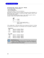
Page 106: ...Free Disks and Array Disks lists In the example above 1 0 M means the hard drive is attached to Channel 1 Controller 0 and the drive is set to Master The following is a list of all possible combinations Parallel ATA 0 0 M Channel 0 controller 0 Master 0 0 S Channel 0 controller 0 Slave 0 1 M Channel 0 controller 1 Master 0 1 S Channel 0 controller 1 Slave Serial ATA 1 0 M Channel 1 controller 0 Ma...

Page 107: ...l which is 32KB but the values can be between 4 KB and 128 KB Assigning the Disks The disks that you enabled from the RAID Config BIOS setup page appear in the Free Disks block These are the drives that are available for use as RAID array disks To designate a free disk to be used as a RAID array disk 1 Tab to the Free Disks section The first disk in the list is selected 2 Move it from the Free Dis...

Page 108: ...e set up 3 Use the arrow keys to select the array that you want to set up then press Enter The Array Detail window appears 4 If you want to mark this disk as empty and wipe out all its contents then press C 5 At the prompt press Y to wipe out all the data otherwise press N 6 Press Enter again to go back to the previous window and then press Ctrl X to exit the RAID setup Now that the RAID setup has...

Page 109: ...ed This section describes how to run the setup application and install the RAID software which will upgrade the Windows IDE driver and install the RAID software 1 Start the nForce Setup program to open the NVIDIA Windows nForce Drivers page 2 Select the modules that you want to install Make sure that the NVIDIA IDE Driver is selected 3 Click Next and then follow the instructions 4 After the instal...

Page 110: ...RIVER and then press Enter 3 Press S again at the Specify Devices screen then press Enter 4 Select NVIDIA NForce Storage Controller and then press Enter The follow ing Windows Setup screen appears listing both drivers MSI Reminds You Please follow the instruction below to make an nVIDIA RAID driver for yourself 1 Insert the MSI CD into the CD ROM drive 2 Ignore the Setup screen and use Explorer to...

Page 111: ...nstructions on how to install Windows XP During the GUI portion of the install you might be prompted to click Yes to install the RAID driver Click Yes as many times as needed in order to finish the installation This will not be an issue with a signed driver MSI Reminds You Each time you add a new hard drive to a RAID array the RAID driver will have to be installed under Windows once for that hard ...

Page 112: ...l Panel Switch to Classic View then open the Administrative Tools folder and double click on Computer Management 2 Click Disk Management under the Storage section The Initialize and Convert Disk Wizards appears 3 Click Next The Select Disks to Initialize window appears The disks listed depend on how many arrays you have configured 4 Click Next The Select Disks to Convert window appears ...

Page 113: ...inish The Computer Management window appears The actual disks listed will depend on your system and the unallocated partition is the total combined storage of two hard disks You must format the unallocated disk space in order to use it 7 Format the unallocated disk space Right click Unallocated space select New Partition and follow the wizard After the drive has been formatted it is ready for use ...

Page 114: ...onfiguration from Windows launch the NVRAID Management utility by double clicking NvRaidMan exe the default location of NvRaidMan exe is in nVidia System CK804 IDE WinXP raidtool or nVidia System CK804 IDE Win2K raidtool of the setup CD accompanied with your mainboard The RAID configuration information appears in the right side pane as shown below MSI Reminds You The information in the figures in ...

Page 115: ...l disk space used is 111 80 GB NVRAID Striped Mirror Array The figure below shows an example of a four hard drive stripe mirrored array The total disk space used is 111 80 GB NVRAID Spanning JBOD Array The figure below shows an example of a two hard drive spanning array The total disk space used is 111 80 GB NVRAID Mirrored Array and a Striped Array The figure below shows an example of a two hard ...

Page 116: ...sk will be automatically assigned to the mirrored array to be used instead of the failed disk Dedicated Disk A dedicated free disk is a disk that is assigned to a RAID 1 or RAID 0 1 array and that disk is used by that array only when needed for example during a system crash where a RAID mirrored drive is broken The dedicated disk can be used only by the array that it is assigned to and not by any ...

Page 117: ...m The drive appears under the Free Disk section Step 2 Dedicate the Free Disk to an Array While running NVRAIDMAN dedicate the free disk to an array using one of the following two methods Method 1 Select a free disk and then assign it to an array Method 2 Select an array and then assign a free disk to it Both methods are equally simple ways of accomplishing the same task Method 1 Select a free dis...

Page 118: ...g the NVIDIA Spare Disk Allocation page appears 6 Click Finish As shown in figure below the ST380023AS drive is now a dedicated free disk in the mirrored array If a system crash occurs that causes any of the two ST360015A drives to fail the ST380023AS hard drive will take over and be used in the newly formed mirrored array Once a dedicated disk has been assigned to a particular array it can be rem...

Page 119: ...want to assign a dedicated free disk The pop up menu appears 2 Select Designate Spare from the menu to launch the Spare Disk Allocation Wizard 3 Click Next The Free Disk Selection page appears 4 From the Free Disk Selection page select one of the disks from the list Please note that there can be more than one disk to choose from ...

Page 120: ...location page appears 6 Click Finish You have now assigned a dedicated free disk to a mirrored array Once a dedicated disk has been assigned to a particular array it can be removed at any time To remove the disk right click on the dedicated disk and select the option to remove it ...

Page 121: ...rray type or the array drives as shown in the figure below Then click Designate Spare to launch the Spare Disk Allocation Wizard 2 Click Designate Spare and then follow the instructions in the Wizard The figure below shows an example of a RAID 1 array that has one spare disk dedicated to it Once a dedicated disk has been assigned to a particular array it can be removed at any time To remove the di...

Page 122: ...hard drives This only applies to RAID 1 array as well as a RAID 0 1 array Rebuilding Instructions After creating a mirrored array you can rebuild the array using the following steps 1 Go to Windows and run the NVRAID Management utility The figure below shows an example of a system with one mirrored array 2 Right click on Mirroring The popup menu appears 3 From the popup menu click Rebuild Array Th...

Page 123: ... Next The Completing the NVIDIA Rebuild Array page appears 6 Click Finish The array rebuilding starts after a few seconds and a small pop up message appears towards the bottom right corner of the screen as shown in the figure below During the rebuilding process the NVRAID Management utility screen shows the status under the System Tasks and Details sections ...

Page 124: ...D1 and or RAID 0 1 Rebuilding does not apply to RAID 0 and JBOD arrays You Can Use Any Available Free Disk You can rebuild a mirrored array using any available Free Disk or Dedicated Disk For example the figure below shows a mirrored array using 34 48 GB HD while having two Free Disks each 55 90 GB large To use one of these available free disks to rebuild your array follow the same steps as explai...

Reviews: