background image

2-10


MS-7125 ATX Mainboard

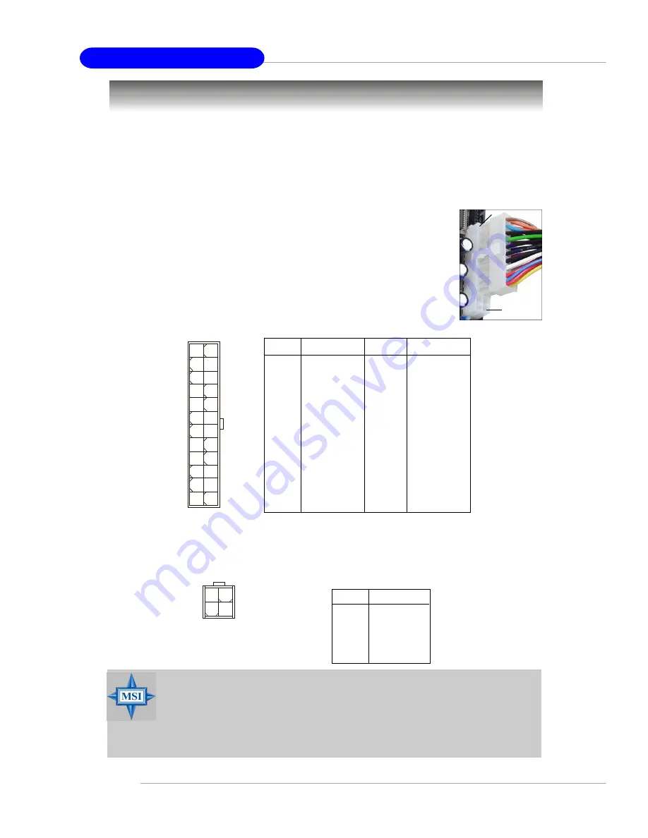
Power Supply

The mainboard supports ATX power supply for the power system.  Before inserting
the power supply connector, always make sure that all components are installed
properly to ensure that no damage will be caused.

PIN

SIGNAL

13

+3.3V

14

-12V

15

GND

16

PS-ON#

17

GND

18

GND

19

GND

20

Res

21

+5V

22

+5V

23

+5V

24

GND

PIN

SIGNAL

 1

+3.3V

 2

+3.3V

 3

GND

 4

+5V

 5

GND

 6

+5V

 7

GND

 8

PWR OK

 9

5VSB

10

+12V

11

+12V

12

NC

 Pin Definition

ATX 24-Pin Power Connector: ATX1

This connector allows you to connect an SSI power supply. To connect the

SSI power supply, make sure the plug of the power supply is
inserted in the proper orientation and the pins are aligned. Then
push down the power supply firmly into the connector.

You may use the 20-pin ATX power supply or 24-pin SSI

power supply as you like. If you’d like to use the ATX power supply,
please plug your power supply along with pin 1 & pin 13 (refer to
the image at the right hand). There is also a foolproof design on pin
11, 12, 23 & 24 to avoid wrong installation.

pin 12

pin 13

ATX1

12

1

13

24

PIN

SIGNAL

1

GND

2

GND

3

12V

4

12V

 JPW1 Pin Definition

ATX 12V Power Connector: JPW1

This 12V power connector is used to provide power to the CPU.

MSI Reminds You...

1. These two connectors connect to the ATX power supply and have to

work together to ensure stable operation of the mainboard.

2. Power supply of 350 watts (and above) is highly recommended for

system stability.

3. For ATX 12V power connection, it should be greater than 18A.

JPW1

1

3

4

2

Summary of Contents for K8NNeo4 Platinum Series

Page 1: ...i MS 7125 v1 X ATX Mainboard K8N Neo4 Series G52 M7125X1...

Page 2: ...pment in a residential area is likely to cause harmful interference in which case the user will be required to correct the interference at his own expense Notice 1 The changes or modifications not exp...

Page 3: ...rnational Business Machines Corporation Microsoft is a registered trademark of Microsoft Corporation Windows 98 2000 NT XP are registered trademarks of Microsoft Corporation NVIDIA the NVIDIA logo Dua...

Page 4: ...sonnel h The power cord or plug is damaged h Liquid has penetrated into the equipment h The equipment has been exposed to moisture h The equipment has not work well or you can not get it work accordin...

Page 5: ...ortant Notification about Power Issue 2 11 Back Panel 2 12 Mouse Connector Green Keyboard Connector Purple 2 12 IEEE1394 Port Optional 2 12 Serial Port Connector 2 13 USB Connectors 2 13 LAN RJ 45 Jac...

Page 6: ...1 Entering Setup 3 2 Selecting the First Boot Device 3 2 Control Keys 3 3 Getting Help 3 3 The Main Menu 3 4 Standard CMOS Features 3 6 Advanced BIOS Features 3 8 Advanced Chipset Features 3 10 Integ...

Page 7: ...allation 5 7 Installing the RAID Driver for bootable RAID Array 5 7 Installing the NVIDIA RAID Software Under Windows for Non bootable RAID Array 5 9 Initializing and Using the Disk Array 5 10 RAID Dr...

Page 8: ...ical Drive Information 6 13 Reserved Drive and Setting Size for RAID set Spare Drive or JBOD 6 14 Installing the RAID Driver For bootable RAID Array 6 15 Installing Driver in Windows XP 2000 Server 20...

Page 9: ...TX mainboard The K8N Neo4 Platinum mainboard is based on nVIDIA nForce 4 Ultra chipset for optimal system efficiency Designed to fit the advanced AMD K8 Athlon 64 FX Athlon 64 processor the K8N Neo4 P...

Page 10: ...2 5v DDR SDRAM DIMM For the updated supporting memory modules please visit http www msi com tw program products mainboard mbd pro_mbd_trp_list php Slots h One PCI Express x16 slot supports PCI Express...

Page 11: ...l LAN jacks 1st LAN supports 10 100 1000 Fast Ethernet by Marvell 88E1111 2nd LAN supports 10 100 1000 Fast Ethernet by Marvell 88E8053 IEEE 1394 Optional h Supports up to two 1394 ports rear panel x...

Page 12: ...Mounting h 9 mounting holes MSI Reminds You 1 Now the nVidia nForce4 system driver is only available for Windows 2000 and Windows XP 2 To create a bootable RAID volume for a Windows 2000 environment M...

Page 13: ...ports Optional Winbond W83627THF Silicon Image SATALink Sil3114CT176 Optional VIA VT6307 Optional 88E1111 RCJ Optional BATT DIMM 1 SFAN1 DIMM 3 DIMM 2 DIMM 4 ATX1 PCI Slot 3 PCI Slot 2 PCI Slot 1 PCI...

Page 14: ...Power Cable SATA Cable Optional User s Guide Test Report D Bracket 2 Optional MSI motherboard MSI Driver Utility CD SATA RAID Driver Diskette Round Cable of IDE Devices Back IO Shield Quick Guide 1394...

Page 15: ...les and expansion cards as well as how to setup the jumpers on the mainboard Also it provides the instructions on connecting the periph eral devices such as the mouse keyboard etc While doing the inst...

Page 16: ...1 p 2 10 IDE1 2 p 2 17 ATX1 p 2 10 JFP2 p 2 19 PCI_E2 p 2 26 PCI Slots 1 4 p 2 26 JUSB1 3 p 2 19 SATA1 4 p 2 18 J1394_1 p 2 21 Optional NBFAN1 p 2 16 CPUFAN1 p 2 16 JAUD1 p 2 20 SW1 p 2 25 FDD1 p 2 16...

Page 17: ...mbd pro_mbd_cpu_support php MSI Reminds You Overheating Overheating will seriously damage the CPU and system always make sure the cooling fan can work properly to protect the CPU from overheating Repl...

Page 18: ...CPU is correctly installed the pins should be completely embedded into the socket and can not be seen Please note that any violation of the correct installation procedures may cause permanent damages...

Page 19: ...our dealer to purchase and install them before turning on the computer 1 Detach the shield of the backplate s paster 2 Turn over the mainboard and install the backplate to the proper position 3 Turn o...

Page 20: ...on the top of the retention mechanism 7 Fasten down the lever 8 Make sure the safety hook completely clasps the fixed bolt of the retention mechanism Safety Hook Fixed Bolt Fixed Lever 9 Attach the CP...

Page 21: ...DDR but there are some rules while using dual channel DDR Please refer to the suggested DDR population table below Users may install memory modules of different type and density on different channel...

Page 22: ...LE slots while the GREEN slots are left empty This mainboard DO NOT support the memory module installed with more than 18 pieces of IC integrated circuit DIMM1 Ch A DIMM2 Ch B DIMM3 Ch A DIMM4 Ch B Sy...

Page 23: ...minds You You can barely see the golden finger if the module is properly in serted in the socket MSI Reminds You 1 The maximum memory speed decreases when the following two Memory Combination is selec...

Page 24: ...nd the pins are aligned Then push down the power supply firmly into the connector You may use the 20 pin ATX power supply or 24 pin SSI power supply as you like If you d like to use the ATX power supp...

Page 25: ...es Due to several pins are very sensitive to ESD so this kind of memory replacement actions might cause system chipset unable to boot Please follow the following solution to avoid this situation Unplu...

Page 26: ...d data 2 NC Noconnection 3 GND Ground 4 VCC 5V 5 Mouse KeyboardClock Mouse Keyboardclock 6 NC Noconnection Pin Definition Keyboard COM Port USB Ports L Out Mic L In Mouse Parallel LAN Optional 1394 Po...

Page 27: ...ta Channel 1 7 Data 1 Positive Data Channel 1 8 GND Ground USB Port Description Serial Port Connector The mainboard offers one 9 pin male DIN connector as the serial port The port is a 16550A high spe...

Page 28: ...devices Mic is a connector for microphones However there is an advanced audio application provided by Realtek ALC850 to offer support for 7 1 channel audio operation and can turn rear audio connectors...

Page 29: ...mode 13 1 14 25 PIN SIGNAL DESCRIPTION 1 STROBE Strobe 2 DATA0 Data0 3 DATA1 Data1 4 DATA2 Data2 5 DATA3 Data3 6 DATA4 Data4 7 DATA5 Data5 8 DATA6 Data6 9 DATA7 Data7 10 ACK Acknowledge 1 1 BUSY Busy...

Page 30: ...r When connecting the wire to the connectors always take note that the red wire is the positive and should be connected to the 12V the black wire is Ground and should be connected to GND If the mainbo...

Page 31: ...etting the jumper accordingly IDE2 Secondary IDE Connector IDE2 can also connect a Master and a Slave drive IDE1 IDE2 MSI Reminds You If you install two hard disks on cable you must configure the seco...

Page 32: ...e ports Each supports 1st generation serial ATA data rates of 300MB s SATA1 4 150 MB s SATA5 8 Both connectors are fully compliant with Serial ATA 1 0 specifications Each Serial ATA connector can conn...

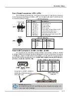
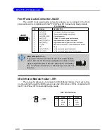
Page 33: ...ted correctly or it may cause some damage 7 8 Power LED Speaker 1 2 JFP2 JFP1 1 9 10 2 Power LED Power Switch Reset Switch HDD LED PIN SIGNAL DESCRIPTION 1 HD_LED_P Hard disk LED pull up 2 FPPWR SLP M...

Page 34: ...future use to control headphone amplifier 8 KEY No pin 9 AUD_FPOUT_L Left channel audio signal to front panel 10 AUD_RET_L Left channel audio signal return from front panel Pin Definition MSI Reminds...

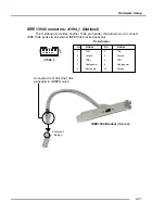
Page 35: ...IEEE 1394 Connectors J1394_1 Optional The mainboard provides another 1394 pin header that allows you to connect IEEE 1394 ports via an external IEEE1394 bracket optional Pin Definition PIN SIGNAL PIN...

Page 36: ...fy system problem through 16 various combinations of LED signals Pin Signal 1 DBG1 high for green color 2 DBR1 high for red color 3 DBG2 high for green color 4 DBR2 high for red color 5 DBG3 high for...

Page 37: ...A BIOS This will start writing VGA sign on message to the screen D Bracket 2 D Bracket 2 is an external USB bracket integrating four Diagnostic LEDs which use graphic signal display to help users unde...

Page 38: ...e video adapter BIOS Sign On This will start showing information about logo proces sor brand name etc Testing Base and Extended Memory Testing base memory from 240K to 640K and extended memory above 1...

Page 39: ...on Button Clear CMOS Button SW1 There is a CMOS RAM on board that has a power supply from external battery to keep the system configuration data With the CMOS RAM the system can auto matically boot OS...

Page 40: ...ance graphics infrastructure for Desktop Platforms doubling the capability of existing AGP8x de signs with transfer rates of 4 0 GB s over a PCI Express x16 lane for graphics controllers while PCI Exp...

Page 41: ...are lines over which devices can send interrupt signals to the microprocessor The PCI IRQ pins are typically connected to the PCI bus INT A INT D pins as follows Order 1 Order 2 Order 3 Order 4 PCI Sl...

Page 42: ...ibed in this chapter are under continuous update for better system performance Therefore the description may be slightly different from the latest BIOS and should be held for reference only 2 While bo...

Page 43: ...y Selecting the First Boot Device You are allowed to select the 1st boot device without entering the BIOS setup utility by pressing F11 When the same message as listed above appears on the screen pres...

Page 44: ...up the sub menu Then you can use the control keys to enter values and move from field to field within a sub menu If you want to return to the main menu just press the Esc General Help F1 The BIOS set...

Page 45: ...ntegrated peripherals Power Management Setup Use this menu to specify your settings for power management PNP PCI Configurations This entry appears if your system supports PnP PCI H W Monitor Use this...

Page 46: ...the BIOS values for the best system performance but the system stability may be affected BIOS Setting Password Use this menu to set the password for BIOS Save Exit Setup Save changes to CMOS and exit...

Page 47: ...ns of your drive must match with the drive table The hard disk will not work properly if you enter improper information for this category If your hard disk drive type is not matched or listed you can...

Page 48: ...is detected at boot Available options are All Errors The system stops when any error is detected No Errors The system doesn t stop for any detected error All But Keyboard The system doesn t stop for a...

Page 49: ...nterrupt Controller Due to compliance with PC2001 design guide the system is able to run in APIC mode Enabling APIC mode will expand available IRQ resources for the system Settings Enabled Disabled MP...

Page 50: ...lows the system to try to boot from other device if the system fails to boot from the 1st 2nd 3rd boot device Hard Disk Boot Priority Press Enter to enter the sub menu Then you may use the arrow keys...

Page 51: ...omatically detect all of the DRAM timing If you set this field to Manual the following fields will be selectable The settings are Auto Manual Memclock index value Mhz When the Timing Mode is set to Ma...

Page 52: ...strobe to CAS column address strobe The less the clock cycles the faster the DRAM performance Setting options Auto 2T 3T 4T 5T 6T 7T Row Precharge Time Trp When the Timing Mode is set to Manual the f...

Page 53: ...ut must be considered due to routing laten cies on the clock forwarded bus It is counted from the first address bus slot that was not associated with part of the read burst Available settings Auto 1T...

Page 54: ...ns 9ns 9 5ns Async Latency value When the User Config mode is set to Manual the field is adjustable This field should be loaded with 4 bit value equal to th e maximum asynchronous latency in the DRAM...

Page 55: ...operating system Setting options Enabled Disabled Onboard LAN Control This setting controls the onboard LAN controller Setting options Enabled Disabled OnBoard LAN Option ROM This setting is used to e...

Page 56: ...e the controller if you want to use other controller cards to connect an audio device The settings are Auto Disabled Onboard FDC Controller Select Enabled if your system has a floppy disk controller F...

Page 57: ...the TxD and RxD signals Setting options RxD2 TxD2 IR Rx2Tx2 Parallel Port There is a built in parallel port on the on board Super I O chipset that provides Standard ECP and EPP features It has the fol...

Page 58: ...Enabled Disabled IDE DMA Transfer Access This item is used to enable or disable the DMA transfer function of the IDE Hard Drive The settings are Enabled Disabled SATA1 SATA2 SATA3 SATA4 This item is...

Page 59: ...ster Slave RAID This feature allows users to enable or disable the RAID function for each IDE hard disk drive Settings Enabled Disabled SATA 1 2 3 4 RAID This feature allows users to enable or disable...

Page 60: ...in formation of system configuration and open applications files is saved to main memory that remains powered while most other hardware components turn off to save energy The information stored in mem...

Page 61: ...system to the status before power failure or interrupt occurred Wake Up Event Activity Press Enter and the following sub menu appears Resume S3 by PS2 Keyboard Resume S3 by PS2 Mouse These fields allo...

Page 62: ...means abso lutely nothing unless you are using a Plug and Play operating system such as Win dows 95 98 If you set this field to Manual choose specific resources by going into each of the sub menu tha...

Page 63: ...e operating system it signals this by causing an IRQ to occur After receiving the signal when the operating system is ready the system will interrupt itself and perform the service required by the I O...

Page 64: ...tions Enabled Reset Disabled Smart CPU Fan Target There are 2 pairs of Temperature FAN Speed control System Temperature with System Fan and CPU Temperature with CPU Fan W83627THF provides the Smart Fa...

Page 65: ...R Read only MSI Reminds You Change these settings only if you are familiar with the chipset High Performance Mode This field allows you to select the DDR timing setting Setting options Manual Optimize...

Page 66: ...rclocking increasing the CPU frequency by 7 General 5th level of overclocking increasing the CPU frequency by 9 Commander 6th level of overclocking increasing the CPU frequency by 11 MSI Reminds You E...

Page 67: ...e SSE extensions con sist of a new set of instructions and a new set of registers These instructions and registers are designed to allow Single Instruction Multiple Data SIMD computations to be made o...

Page 68: ...ing the DDR voltage can increase the DDR speed Any changes made to this setting may cause a stability issue so changing the DDR voltage for long term purpose is NOT recommended Setting options are Aut...

Page 69: ...ized Defaults are the default values set by the mainboard manufacturer specifically for optimal performance of the mainboard The Fail Safe Defaults are the default values set by the BIOS vendor for st...

Page 70: ...and press Enter You may also press Esc to abort the selection and not enter a password To clear a set password just press Enter when you are prompted to enter the password A message will show up confi...

Page 71: ...anagement and communication 802 11g WLAN settings Moreover with this unique utility you will be able to activate the MSI well known features Live Update and Core Center which makes it easier to update...

Page 72: ...menu to make further configuration MSI Click on this button to link to MSI website http www msi com tw Quick Guide Click on this button and the quick guide of DigiCell will be displayed for you to re...

Page 73: ...tem this icon will be lit up Click this blue icon to turn DigiCell into a MP3 player and then you can load media files from your MEGA STICK or the system and edit the preferred playlist Audio Speaker...

Page 74: ...stic sub menu you can see the information status and note of each DigiCell You may double check the connection and installation of the item marked as gray You may also click on the Mail to MSI button...

Page 75: ...your system Click on each item for details This icon indicates the information and connection status of onboard LAN which is read only The second icon indicates the wireless connection You may click t...

Page 76: ...network is a local area network or other small network especially one with wireless or temporary plug in connections in which some of the network devices are part of the network only for the duration...

Page 77: ...rnet in office usually the LAN card will automatically get the IP this computer uses In this case you don t have to enable this function SSID Means Service Set Identifier a unique name shared among al...

Page 78: ...are selecting is encrypted WEP shown in the Encryption column the screen will display as below You need to enter the correct WEP key defined by AP in the specified WEP Key 1 4 fields to make the conn...

Page 79: ...r on the screen Double click the MSI Live Update 3 icon and the following screen will appear Six buttons are placed on the left column of the screen Click the desired button to start the update proces...

Page 80: ...the Play List field and use Delete button to remove the media file from the play list You may remove multi media files simultaneously by using Ctrl to select multi files Shuffle To play the media file...

Page 81: ...rewind Right click on the MP3 file and choose Info a MP3 Info dialogue will pop up to show the information of the file including the title artist album release year and others You may also add your o...

Page 82: ...install the Supplemental Language Support provided by Microsoft to solve this problem You need to have your Microsoft Setup CD prepared in the CD ROM The system will start to install the necessary com...

Page 83: ...select the language you want to be supported the language of the filename in the MegaStick from the drop down list in the Language for non Unicode programs then click Apply The system will install th...

Page 84: ...ng When the CPU temperature climbs up to a certain degree the speed of the system cooling fan will be risen automatically On the other hand the speed of the system cooling fan will slow down instantly...

Page 85: ...item then click OK to apply the changes The values you set for the temperatures are the maximum thresholds for the system warnings and the values for fan speeds are the minimum thresholds Center side...

Page 86: ...er to regulate the current playing digital sound source Also you may click on the on button to enable disable the equalizer function Once the equalizer function is enabled you can choose several prese...

Page 87: ...nges Then the following screen will appear In this Speaker Configuration dialogue box first select the correct item from the Speaker mode drop down list and then click on each connected speaker to ens...

Page 88: ...on Date Use the drop down list to select the date for power on Time Use the arrow keys to select the hour minute second for power on power off and restarting Then click Apply to save the changes As yo...

Page 89: ...r Step 2 Click on OK to apply the setting Step 3 For specified file or specified website you may enter the file name with the complete path or the website link in the Parameters field Of course you ma...

Page 90: ...eature It supports the following operating systems Win9X Windows ME Windows 2000 Windows XP Default User Name It is only available for Windows 2000 Windows XP If you are using a computer belonging to...

Page 91: ...is used by the world s leading businesses to the common PC desktop This technology uses multiple drives to either increase total disk space or to offer data protection For all levels RAID techniques o...

Page 92: ...Drawbacks Hard Disks Fault Tolerance RAID 0 Non critical data requiring high performance High data throughput No fault tolerance multiple None RAID 1 Small databases or any other small capacity enviro...

Page 93: ...at has the RAID driver to copy and install the nForce RAID software Check p 5 9 for details 4 Initialize the NVRAID Array Disks Setting Up the NVRAID BIOS Be sure to enable the IDE RAID or SATA RAID i...

Page 94: ...ree Disks and Array Disks lists In the example above 1 0 M means the hard drive is attached to Channel 1 Controller 0 and the drive is set to Master The following is a list of all possible combination...

Page 95: ...which is 32KB but the values can be between 4 KB and 128 KB Assigning the Disks The disks that you enabled from the RAID Config BIOS setup page appear in the Free Disks block These are the drives tha...

Page 96: ...set up 3 Use the arrow keys to select the array that you want to set up then press Enter The Array Detail window appears 4 If you want to mark this disk as empty and wipe out all its contents then pr...

Page 97: ...ss Enter 3 Press S again at the Specify Devices screen then press Enter 4 Select NVIDIA NForce Storage Controller and then press Enter The follow ing Windows Setup screen appears listing both drivers...

Page 98: ...ructions on how to install Windows XP During the GUI portion of the install you might be prompted to click Yes to install the RAID driver Click Yes as many times as needed in order to finish the insta...

Page 99: ...is enabled This section describes how to run the setup application and install the RAID software which will upgrade the Windows IDE driver and install the RAID software 1 Start the nForce Setup progra...

Page 100: ...Panel Switch to Classic View then open the Administrative Tools folder and double click on Computer Management 2 Click Disk Management under the Storage section The Initialize and Convert Disk Wizard...

Page 101: ...nish The Computer Management window appears The actual disks listed will depend on your system and the unallocated partition is the total combined storage of two hard disks You must format the unalloc...

Page 102: ...VRAID Management utility by clicking Start Programs NVIDIA Corporation RAID Manager RAID M a n a g e r t h e d e f a u l t l o c a t i o n o f N v R a i d M a n e x e i s i n nVidia System CK804 IDE W...

Page 103: ...disk space used is 111 80 GB NVRAID Striped Mirror Array The figure below shows an example of a four hard drive stripe mirrored array The total disk space used is 111 80 GB NVRAID Spanning JBOD Array...

Page 104: ...k will be automatically assigned to the mirrored array to be used instead of the failed disk Dedicated Disk A dedicated free disk is a disk that is assigned to a RAID 1 or RAID 0 1 array and that disk...

Page 105: ...The drive appears under the Free Disk section Step 2 Dedicate the Free Disk to an Array While running NVRAIDMAN dedicate the free disk to an array using one of the following two methods Method 1 Sele...

Page 106: ...location page appears 6 Click Finish As shown in figure below the ST380023AS drive is now a dedicated free disk in the mirrored array If a system crash occurs that causes any of the two ST360015A driv...

Page 107: ...ant to assign a dedicated free disk The pop up menu appears 2 Select Designate Spare from the menu to launch the Spare Disk Allocation Wizard 3 Click Next The Free Disk Selection page appears 4 From t...

Page 108: ...ocation page appears 6 Click Finish You have now assigned a dedicated free disk to a mirrored array Once a dedicated disk has been assigned to a particular array it can be removed at any time To remov...

Page 109: ...ray type or the array drives as shown in the figure below Then click Designate Spare to launch the Spare Disk Allocation Wizard 2 Click Designate Spare and then follow the instructions in the Wizard T...

Page 110: ...ard drives This only applies to RAID 1 array as well as a RAID 0 1 array Rebuilding Instructions After creating a mirrored array you can rebuild the array using the following steps 1 Go to Windows and...

Page 111: ...Next The Completing the NVIDIA Rebuild Array page appears 6 Click Finish The array rebuilding starts after a few seconds and a small pop up message appears towards the bottom right corner of the scree...

Page 112: ...lding an array works only when using RAID1 and or RAID 0 1 Rebuilding does not apply to RAID 0 and JBOD arrays You Can Use Any Available Free Disk You can rebuild a mirrored array using any available...

Page 113: ...BOD just a bunch of disks functionality to enhance the industry s leading PCI to SATA host controller products Two major chal lenges facing the storage industry today are keeping pace with the increas...

Page 114: ...ovide fault tolerance Striping arrays use multiple disks to form a larger virtual disk RAID 1 Mirroring Disk mirroring creates an identical twin for a selected disk by having the data simultaneously w...

Page 115: ...g parity stripes The data and parity information is arranged on the disk array so that parity is written to different disks There are at least 3 members to a Parity RAID set The following example illu...

Page 116: ...on disk drives can be formatted as independent logical drives h Adjustable Stripe Size for RAID 0 RAID 5 and RAID 10 h Uses the Self Monitoring Analysis and Reporting Technology SMART feature in the a...

Page 117: ...ing boot up a screen similar to that below will appear for about 5 seconds Press CTRL S or the F4 key to enter the BIOS RAID utility The RAID Utility menu screen will be displayed A brief description...

Page 118: ...et allocated spare and unallocated physical drive attached to the SATA host adapter These operations are detailed in the pages that follow Help Window This window displays context sensitive help and s...

Page 119: ...ty and number of drives available It is best to carefully consider the long term role of the system and plan the data storage strategy appropriately Silicon Image has made the creation of RAID sets ve...

Page 120: ...ed in both BIOS and in the SATARaid5 GUI If you have excess capacity left on your hard drives after creating a RAID set in the BIOS you can later go to the SATARaid5 GUI to create additional logical d...

Page 121: ...ay before completing the configuration Answer N to abort the creation of the JBOD or Y to proceed with the JBOD creation Deleting RAID Groups Spare Drive and JBOD 1 To remove one or more RAID sets spa...

Page 122: ...ncludes drive connection information including the channel on the host adapter to which it is connected If after a disk failure the replacement disk was previously part of a RAID set or used in anothe...

Page 123: ...6 11 Silicon Image SATARAID5TM Introduction 2 Select the Conflict entry in the Logical Drive Status window and press Enter...

Page 124: ...E Be aware of this when performing a conflict resolution To maintain the same drive lettering the SATA cables connected to the drives may need to be swapped or in the case of a SATA based removable d...

Page 125: ...ing the drive under Windows is usually sufficient to prepare the drive for use Logical Drive Information This menu item allows the display of the assignment of physical drives within a logical set RAI...

Page 126: ...cal drive and it will not report the drive to the system BIOS When user selects to create a RAID set spare drive or JBOD he or she has to select size for the set or drive BIOS will set a default size...

Page 127: ...03 installation h Installing OS on RAID Drive 1 After setup examines your disks it will copy files to Windows installation folders and restart the system 2 The setup program will continue and finish t...

Page 128: ...e Java 2 Runtime Installer and executable package must be downloaded from the Sun Microsystems website at http java sun com j2se downloads html The computer must have an Internet connection set up bef...

Page 129: ...window appears asking for acceptance the license agreement select I accept the terms of this license agreement and click Next When the installation completes click Finish Restart the computer when pro...

Page 130: ...provides a setup CD along with your mainboard which contains the required drivers for your system and many other use ful and powerful utility to bring you the best experience for your office professi...

Page 131: ...w the proceeding instructions NVIDIA nForce4 System Driver This driver is only available for Windows 2000 and Windows XP operating system Please follow the following step to install the driver correct...

Page 132: ...s to install All the components shown here will be selected to be installed by default Then click Next 3 The system will start installing the selected driver components automatically 4 Then the follow...

Page 133: ...of NVIDIA Firewall and ForceWare Network Access Manager It is a software firewall to protect the softwares from hacking However it is strongly suggested that you do not install this component Please...

Page 134: ...on to install the Realtek AC97 Audio Driver Then the welcome dialogue will display Click Next to continue The installation process will launch automatically 2 The following screen indicates the instal...

Page 135: ...7 6 MS 7125 ATX Mainboard Utility Installation Click on the Utility tab and the screen below will display Click on the utility you like to install and follow the proceeding instructions...

Reviews: