2-16
M S-7368 M ainboard
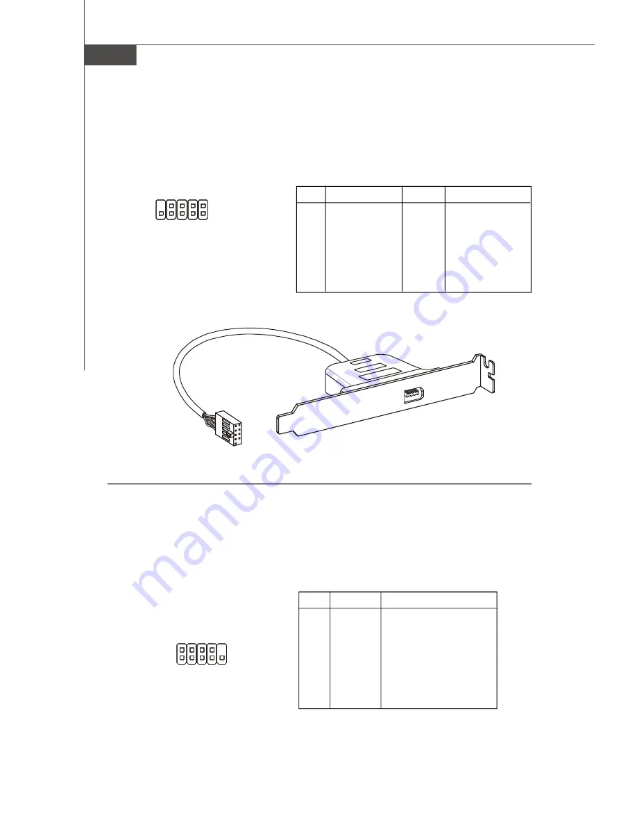
IEEE1394 Connector: J1394_1(Optional)
This connector allows you to connect the IEEE1394 device via an optional IEEE1394
bracket.
Pin Definition
PIN
SIGNAL
PIN
SIGNAL
1
TPA+
2
TPA-
3
Ground
4
Ground
5
TPB+
6
TPB-
7
Cable power
8
Cable power
9
Key (no pin)
10
Ground
J1394_1
1
9
2
10
IEEE1394 Bracket
(Optional)
Serial Port Connector: JCOM1
This connector is a 16550A high speed communication port that sends/receives 16
bytes FIFOs. You can attach a serial device.
PIN
SIGNAL
DESCRIPTION
1
DCD
Data Carry Detect
2
SIN
Serial In or Receive Data
3
SOUT
Serial Out or Transmit Data
4
DTR
Data Terminal Ready
5
GND
Ground
6
DSR
Data Set Ready
7
RTS
Request To Send
8
CTS
Clear To Send
9
RI
Ring Indicate
Pin Definition
JCOM1
1
9
2
PDF created with pdfFactory Pro trial version
www.pdffactory.com
Summary of Contents for K9AG Neo2-Digital
Page 1: ...i K9AG Neo2 Digital MS 7368 v1 X Mainboard G52 73681X1 ...
Page 5: ...v WEEE Waste Electrical and Electronic Equipment Statement ...
Page 6: ...vi ...
Page 7: ...vii ...
Page 15: ...MS 7368 Mainboard 1 6 ...
Page 35: ...2 20 MS 7368 Mainboard ...
Page 91: ...MS 7368 Mainboard B 10 ...
Page 103: ...C 12 MS 7368 Mainboard ...


