background image

2-25

Hardware Setup

The motherboard provides the following jumpers for you to set the

computer’s function. This section will explain how to change your
motherboard’s function through the use of jumpers.

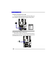
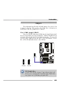
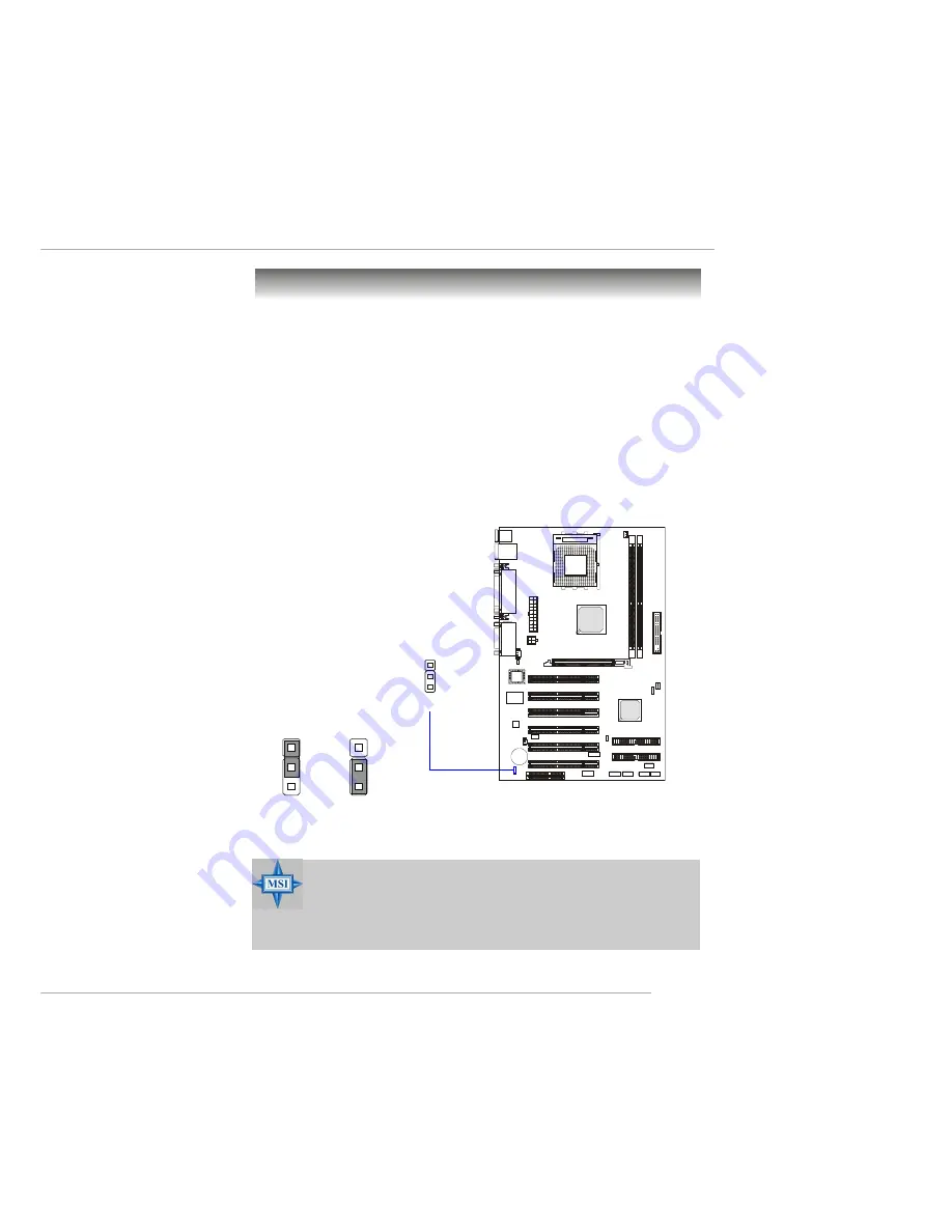
Clear CMOS Jumper: JBAT1

There is a CMOS RAM on board that has a power supply from external

battery to keep the data of system configuration.  With the CMOS RAM, the
system can automatically boot OS every time it is turned on.  If you want to
clear the system configuration, use the JBAT1 (Clear CMOS Jumper ) to clear
data.  Follow the instructions below to clear the data:

Jumpers

JBAT1

1

Clear Data

1

3

Keep Data

1

3

MSI Reminds You...

You can clear CMOS by shorting 2-3 pin while the system is off.
Then return to 1-2 pin position. Avoid clearing the CMOS while
the system is on; it will damage the mainboard.

Summary of Contents for KT3 Ultra2-C MS-6593

Page 1: ...i KT3 Ultra2 C Version 1 0 G52 MA00624 MS 6593 v1 X ATX Mainboard...

Page 2: ...ith the instruction manual may cause harmful interference to radio communications Operation of this equipment in a residential area is likely to cause harmful interference in which case the user will...

Page 3: ...ess Machines Corporation Windows 95 98 2000 NT XP are registered trademarks of Microsoft Corporation Netware is a registered trademark of Novell Inc Award is a registered trademark of Phoenix Technolo...

Page 4: ...module 9 All cautions and warnings on the equipment should be noted 10 Never pour any liquid into the opening that could damage or cause electri cal shock 11 If any of the following situations arises...

Page 5: ...er 1 6 Live Monitor 1 7 D Bracket 2 Optional 1 8 FuzzyLogic 4 1 10 CPU Thermal Protection 1 11 Chapter2 HardwareSetup 2 1 Quick Components Guide 2 2 Central Processing Unit CPU 2 3 CPU Installation Pr...

Page 6: ...FAN1 SFAN1 2 16 CD In Connector J10 2 17 SPDIF Connector JSP1 Optional 2 17 IrDA Infrared Module Header JIR1 2 18 Chassis Intrusion Switch Connector J3 2 18 Front Panel Connectors JFP1 JFP2 2 19 Front...

Page 7: ...Configurations 3 22 Integrated Peripherals 3 24 PC Health Status 3 27 Frequency Voltage Control 3 28 Set Supervisor User Password 3 30 Load High Performance BIOS Setup Defaults 3 31 Appendix Using4 o...

Page 8: ...and provides six USB 2 0 ports for high speed data transmission one SPDIF pinheader for digital audio transmission and one extra Bluetooth pinheader that ful fills your need for wireless connection D...

Page 9: ...egrated USB 2 0 controller MainMemory h Supports four memory banks using two 184 pin DDR DIMMs hSupports up to 2GB PC2700 2100 1600 DDR SDRAMs h Supports 2 5v DDR SDRAM Slots h One AGP Accelerated Gra...

Page 10: ...channel audio LAN Optional h 10 100Mbps Ethernet onboard BIOS h The mainboard BIOS provides Plug Play BIOS which detects the pe ripheral devices and expansion cards of the board automatically h The m...

Page 11: ...GS1 JAUD1 SOCKET 462 BIOS PCI Slot 5 PCI Slot 6 PCI Slot 4 PCI Slot 3 PCI Slot 2 PCI Slot 1 CNR JIR1 JFP1 JBT1 Optional JFP2 JUSB2 JUSB3 JLED T LAN jack B USB ports Optional Top Parallel Port Bottom C...

Page 12: ...on monitorCPU systemtemperatures monitor fan speed s monitor system voltage monitor chassis intrusion If one of the items above is abnormal the program main screen will be immediately shown on the scr...

Page 13: ...ick the MSI Live Update Series 2 icon and the following screen will appear Five buttons are placed on the leftmost pane of the screen Click the desired button to start the update process Live BIOS Upd...

Page 14: ...tor is a tool used to schedule the search for the latest BIOS drivers version on the MSI Web site To use the function you need to install the MSI Live Update Series 2 application After the installatio...

Page 15: ...S This will start writing VGA sign on message to the screen 1 2 3 4 Red Green D Bracket 2 1 2 3 4 D Bracket 2 Optional D Bracket 2 is an external USB bracket integrating four Diagnostic LEDs which use...

Page 16: ...ideo adapter BIOS Sign On This will start showing information about logo processor brand name etc Testing Base and Extended Memory Testing base memory from 240K to 640K and extended memory above 1MB u...

Page 17: ...overclock the CPU FSB Front Side Bus frequency under the Windows operating system click FSB and use the right and left arrow keys to select the desired FSB and then click Apply to apply the new setup...

Page 18: ...platform This CPU Thermal Protection mechanism works on a thermal signal sensor If the mechanism senses an abnormal temperature rise it will automatically shut down the system and the CPU temperature...

Page 19: ...dules and expansion cards as well as how to setup the jump ers on the mainboard Also it provides the instructions on con necting the peripheral devices such the mouse keyboard etc While doing the inst...

Page 20: ...MMs p 2 6 CPU p 2 4 Back Panel I O p 2 9 CFAN1 p 2 16 FDD1 p 2 14 SFAN1 p 2 16 SW3 p 2 26 IDE1 IDE2 p 2 15 JBT1 p 2 21 JFP2 p 2 19 JFP1 p 2 19 JUSB3 p 2 22 JUSB2 p 2 22 JAUD1 p 2 20 JIR1 p 2 18 J3 p 2...

Page 21: ...r dealer to purchase and install them before turning on the computer 1 Pull the lever sideways away from the socket Then raise the lever up to a 90 degree angle 2 Look for the cut edge The cut edge sh...

Page 22: ...quirements AMD Athlon Duron Athlon XP processor with a speed of 600MHz and above requires a LARGER heatsink and fan You also need to add ther mal grease between the CPU and heatsink to improve heat di...

Page 23: ...re If CPU Clock 100MHz Core Bus ratio 14 then CPU core speed Host Clock x Core Bus ratio 100MHz x 14 1 4 GHz MSI Reminds You Replacing CPU While replacing the CPU always turn off the ATX power sup ply...

Page 24: ...DR DIMM slots DDR 1 2 Memory DDR DIMM Slots DDR 1 2 Introduction to DDR SDRAM DDR Double Data Rate SDRAM is similar to conventional SDRAM but doubles the rate by transferring data twice per cycle It u...

Page 25: ...module The mod ule will only fit in the right orientation 2 Insert the DIMM memory module vertically into the DIMM slot Then push it in until the golden finger on the memory module is deeply in serted...

Page 26: ...o connect to the ATX power supply make sure the plug of the power supply is inserted in the proper orientation and the pins are aligned Then push down the power supply firmly into the connector ATX 12...

Page 27: ...use You can plug a PS 2 mouse directly into this connector The connector location and pin assignments are as follows PIN SIGNAL DESCRIPTION 1 Mouse DATA Mouse DATA 2 NC No connection 3 GND Ground 4 VC...

Page 28: ...tion Pin Definition PS 2 Keyboard 6 pin Female 2 1 3 4 5 6 USB Connectors The mainboard provides a UHCI Universal Host Controller Interface Universal Serial Bus root for attaching USB devices such as...

Page 29: ...or Transmit Data 4 DTR Data Terminal Ready 5 GND Ground 6 DSR Data Set Ready 7 RTS Request To Send 8 CTS Clear To Send 9 RI Ring Indicate Pin Definition 9 Pin Male DIN Connector 1 2 3 4 5 6 7 8 9 RJ 4...

Page 30: ...ECP mode 13 1 14 25 PIN SIGNAL DESCRIPTION 1 STROBE Strobe 2 DATA0 Data0 3 DATA1 Data1 4 DATA2 Data2 5 DATA3 Data3 6 DATA4 Data4 7 DATA5 Data5 8 DATA6 Data6 9 DATA7 Data7 10 ACK Acknowledge 11 BUSY B...

Page 31: ...nectors Line Out Line In MIC Joystick Midi Connector You can connect a joystick or game pad to this connector MSI Reminds You For advanced audio application RealTek ALC650 audio chip is provided to of...

Page 32: ...to connect to FDD IDE HDD case modem LAN USB Ports IR module and CPU System Power Supply FAN Floppy Disk Drive Connector FDD1 The mainboard provides a standard floppy disk drive connector that support...

Page 33: ...is one third faster than earlier record breaking Ultra ATA 100 tech nology and is backwards compatible with the existing Ultra ATA interface IDE1 Primary IDE Connector The first hard drive should alw...

Page 34: ...to the 12V the black wire is Ground and should be connected to GND If the mainboard has a System Hardware Monitor chipset on board you must use a specially designed fan with speed sensor to take advan...

Page 35: ...udio connector SPDIF Connector JSP1 Optional The connector is used to connect SPDIF Sony Philips Digital Inter connect Format interface for digital audio transmission 1 VCC 2 SPDIF 3 NC JSP1 Pin Defin...

Page 36: ...ront Panel I O Connectivity Design Guide Pin Signal 1 NC 2 NC 3 VCC5 4 GND 5 IRTX 6 IRRX JIR1 Pin Definition Chassis Intrusion Switch Connector J3 This connector is connected to a 2 pin chassis switch...

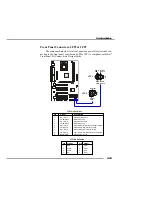
Page 37: ...aker 1 2 7 8 JFP2 PIN SIGNAL DESCRIPTION 1 HD_LED_P Hard disk LED pull up 2 FP PWR SLP MSG LED pull up 3 HD_LED_N Hard disk active LED 4 FP PWR SLP MSG LED pull up 5 RST_SW_N Reset Switch low referenc...

Page 38: ...used by analog audio circuits 5 AUD_FPOUT_R Right channel audio signal to front panel 6 AUD_RET_R Right channel audio signal return from front panel 7 HP_ON Reserved for future use to control headpho...

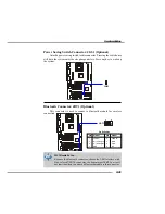
Page 39: ...e switch once will have the system enter the sleep suspend state Press any key to wake up the system JGS1 JBT1 7 8 1 2 MSI Reminds You Because the bluetooth connector shares the USB interface with blu...

Page 40: ...ogy increases data transfer rate up to a maximum throughput of 480Mbps which is 40 times faster than USB 1 1 and is ideal for connecting high speed USB interface peripherals such as USB HDD digital ca...

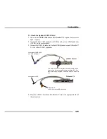
Page 41: ...SB2 pinheader and D Bracket 2 to the yellow JUSB3 pinheader 4 Place the USB 2 0 bracket and D Bracket 2 into the appropriate slot of the system case D Bracket 2 Connected to JUSB3 the yellow USB pinhe...

Page 42: ...integrates four LEDs and allows users to identify system problem through 16 various combinations of LED signals For definitions of 16 signal combinations please refer to D Bracket 2 Optional in Chapte...

Page 43: ...ry to keep the data of system configuration With the CMOS RAM the system can automatically boot OS every time it is turned on If you want to clear the system configuration use the JBAT1 Clear CMOS Jum...

Page 44: ...umper SW3 This jumper provides 100MHz and 133MHz Front Side Bus frequency selection Changing the PSB Processor System Bus speed using this jumper may result in unsupported timing configurations Please...

Page 45: ...rds to meet your needs When adding or removing expansion cards make sure that you unplug the power supply first Meanwhile read the documentation for the expansion card to make any necessary hardware o...

Page 46: ...nd interrupt signals to the microprocessor The PCI IRQ pins are typically connected to the PCI bus INT A INT D pins as follows Order 1 Order 2 Order 3 Order 4 PCI Slot 1 INT A INT B INT C INT D PCI Sl...

Page 47: ...etup program and allows you to configure the system for optimum use You may need to run the Setup program when An error message appears on the screen during the system booting up and requests you to r...

Page 48: ...utility by pressing F11 When the same message as listed above appears on the screen press F11 to trigger the boot menu The POST messages might pass by too quickly for you to respond in time If so rest...

Page 49: ...ults F10 Save all the CMOS changes and exit Getting Help After entering the Setup utility the first screen you see is the Main Menu Main Menu The main menu displays the setup categories the BIOS suppl...

Page 50: ...nge the values in the chipset registers and optimize your system s performance Power Management Features Use this menu to specify your settings for power management PNP PCI Configurations This entry a...

Page 51: ...word Use this menu to set Supervisor Password Set User Password Use this menu to set User Password Load High Performance Defaults Use this menu to load the BIOS values for the best system performance...

Page 52: ...lly the current time The time format is hour minute second System Date This allows you to set the system to the date that you want usually the current date The format is day month date year day Day of...

Page 53: ...perfor Modes mance by optimizing the hard disk timing 32 Bit Transfer Mode Enable 32 bit to maximize the IDE hard disk data transfer rate Floppy Drive A B This item allows you to set the type of flop...

Page 54: ...ds since it will skip some check items Available options Enabled Disabled Full Screen Logo Show This item enables you to show the company logo on the bootup screen Set tings are Enabled Shows a still...

Page 55: ...the first BBS BIOS Boot Specification compliant device BBS 1 The system will boot from the second BBS BIOS Boot Specification compliant device BBS 2 The system will boot from the third BBS BIOS Boot...

Page 56: ...Settings Enabled Disabled BootUp Num Lock This item is to set the Num Lock status when the system is powered on Set ting to On will turn on the Num Lock key when the system is powered on Setting to O...

Page 57: ...S ROM at F0000h FFFFFh resulting in better system performance However if any program writes to this memory area a system error may result Setting options Enabled Disabled C000 32k Shadow This item spe...

Page 58: ...ws you to select which MPS Multi Processor Specification version to be used for the operating system You need to select the MPS ver sion supported by your operating system To find out which version to...

Page 59: ...Chipset Features DRAM Timing Control Press Enter and the following sub menu appears Current Host Clock This item shows the current CPU frequency MSI Reminds You Change these settings only if you are f...

Page 60: ...formance the most while 3 clocks provides the most stable performance Row Precharge Time This item controls the number of cycles for Row Address Strobe RAS to be allowed to precharge If insufficient t...

Page 61: ...ting address and allows internal address counter to properly generate the next memory location The bigger the size the faster the DRAM performance Settings 4 QW 8 QW SDRAM 1T Command This setting cont...

Page 62: ...mory and improves the AGP 4X speed Se lect Enabled only when the installed AGP card supports the function AGP Aperture Size This setting controls just how much system RAM can be allocated to AGP for v...

Page 63: ...ffer to support delayed transactions cycles so that transactions to and from the ISA bus are buffered and PCI bus can perform other transactions while the ISA transaction is underway Select Enabled to...

Page 64: ...can choose to enter the Standby mode in S1 POS or S3 STR fashion through the setting of this field Options are S1 POS The S1 sleep mode is a low power state In this state no system context is lost CPU...

Page 65: ...M Setting to Enabled will activate an Advanced Power Management APM device to enhance Max Saving mode and stop CPU internal clock Settings Disabled Enabled Power Sleep LED This item configures how the...

Page 66: ...sleep mode but if the button is pressed for more than four seconds the computer is turned off After AC Power Loss This setting specifies whether your system will reboot after a power failure or inter...

Page 67: ...elds Available settings for each item are Alarm Date 01 31 Every Day Alarm Hour 00 23 Alarm Minute 00 59 Alarm Second 00 59 MSI Reminds You If you have changed this setting you must let the system boo...

Page 68: ...gs Plug and Play Aware O S When set to Yes BIOS will only initialize the PnP cards used for booting VGA IDE SCSI The rest of the cards will be initialized by the PnP operat ing system like Windows 98...

Page 69: ...to 248 at a 32 increment PCI IDE BusMaster Set this option to Enabled to specify that the IDE controller on the PCI local bus has bus mastering capability Settings options Disabled Enabled Primary Gr...

Page 70: ...oard Serial Port 1 COM A Serial Port 2 COM B Selecting Auto allows AMIBIOS to auto matically determine the correct base I O port address Settings Auto 3F8 COM1 2F8 COM2 3E8 COM3 2E8 COM4 and Disabled...

Page 71: ...he onboard parallel port ECP Normal Bi Dir or EPP EPP Version The item selects the EPP version used by the parallel port if the port is set to EPP mode Settings 1 7 1 9 Parallel Port IRQ When OnBoard...

Page 72: ...m Auto allows the mainboard to detect whether a modem is used If a modem is detected the onboard MC 97 Modem Codec 97 controller will be enabled if not it is disabled Disable the controller if you wan...

Page 73: ...Detection When enabled the system will automatically monitor the CPU fan during boot up If it detects that the CPU fan is not rotating the system will show an error message on the screen and halt the...

Page 74: ...leave the setting at Disabled for optimal system stability and performance But if you are plagued by EMI setting to Enabled for EMI reduction Remember to disable Spread Spectrum if you are overclockin...

Page 75: ...ue so changing the DDR voltage for long term purpose is NOT recommended AGP Voltage V AGP voltage is adjustable in the field allowing you to increase the perfor mance of your AGP display card when ove...

Page 76: ...d When a password has been set you will be prompted to enter it every time you try to enter Setup This prevents an unauthorized person from changing any part of your system configuration Additionally...

Page 77: ...stem performance but may lead to a stability issue When you select Load BIOS Setup Defaults a message as below appears Pressing Enter loads the default values that are factory settings for stable syst...

Page 78: ...audio output including 2 Front 2 Rear 1 Center and 1 Subwoofer channel ALC650 allows the board to attach 4 or 6 speakers for better surround sound effect The section will tell you how to install and u...

Page 79: ...nstallation for Windows 98SE ME 2000 XP For Windows 2000 you must install Windows 2000 Service Pack2 or later before installing the driver The following illustrations are based on Windows XP environme...

Page 80: ...A 3 Using 4 or 6 Channel Audio Function 4 Click Finish to restart the system Click here Click here Select this option...

Page 81: ...l Setting later in the section Make sure all speakers are connected to Line Out connectors Diverse connector configurations for 2 4 and 6 channel using back panel connec tors are described on the next...

Page 82: ...n 1 2 3 6 Channel Analog Audio Output 1 Line Out Front channels 2 Line Out Rear channels 3 Line Out Center and Subwoofer channel Description Both Line In and MIC are converted to Line Out function und...

Page 83: ...k the audio icon from the window tray at the bottom of the screen 2 Select any surround sound effect you prefer from the Environment pull down menu under the Sound Effect tab 3 Click the Speaker Confi...

Page 84: ...A 7 Using 4 or 6 Channel Audio Function 4 The following window appears 5 Select the multi channel operation you prefer from No of Speakers 6 Click OK...

Page 85: ...ace the bad speakers with good ones Testing Each Speaker 1 Click the audio icon from the window tray at the bottom of the screen 2 Click the Speaker Test tab 3 The following window appears 4 Select th...

Page 86: ...ong The function is applied only for 2 channel audio operation so make sure 2 channels mode is selected in the No of Speakers column before playing KaraOK Playing KaraOK 1 Click the audio icon from th...

Page 87: ...CPU FSB 133 will not be autodetected by the motherboard So user need to set the FSB manually to 133 Q Why my motherboard BIOS sticker is Phoenix BIOS but when I boot up my system I saw that Award BIO...

Page 88: ...odownloadtheMSILiveUpdateutilityfromhttp www msi com tw support liveupdate livedriver htmbutitkeepsonfailing A This can be solved by one of the following suggestions 1 Dont install zonealarm 2 Disable...

Page 89: ...OS unless you really have to Q HowdoIupdatetheBIOS A Please refer to http www msi com tw support bios note htm for details Q HowdoIidentifytheBIOSversion A Upon boot up the 1st line appearing after th...

Page 90: ...ROM Insert this floppy disk in the floppy drive Turn On the system and press and hold Ctrl Home to force update It will read the AMIBOOT ROM file and recover the BIOS from the A drive When 4 beeps are...

Page 91: ...unused frequency band of 2 45 GHz that is available globally with some variation of bandwidth in different countries In addition to data up to three voice channels are available Each device has a uni...

Page 92: ...ary circuits for transmitting and receiv ing data a PC chipset provides the electronic interfaces between all subsystems Clock Cycle Clock cycle or tick is the smallest unit of time recognized by a de...

Page 93: ...mass storage devices of up to 8 4 gigabytes whereas the old standard was limited to 528 MB Because of its lower cost enhanced EIDE has replaced SCSI in many areas There are four EIDE modes defined The...

Page 94: ...nterrupt Request Line IRQs are hardware lines over which devices can send interrupt signals to the microprocessor When you add a new device to a PC you sometimes need to set its IRQ number by setting...

Page 95: ...s LPT1 LPT2 and LPT3 It is frequently used by the OS to identify a printer Overclocking Overclocking is resetting your computer so that the microprocessor runs faster than the manufacturer specified s...

Page 96: ...devices to computers SCSI interfaces provide for faster data transmission rates up to 80 megabytes per second than standard serial and parallel ports In addition you can attach many devices to a singl...

Reviews: