


15
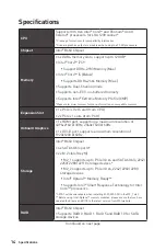
Specifications
Continued from previous page
LAN
1x Realtek® RTL8111H Gigabit LAN Controller
USB
∙
Intel® B460 Chipset
▪
6x USB 3.2 Gen 1 5Gbps ports (4 Type-A ports on the
back panel, 2 ports through the internal USB connector)
▪
6x USB 2.0 ports (2 Type-A ports on the back panel, 4
ports through the internal USB 2.0 connectors)
Audio
Realtek® ALC892 Codec
∙
7.1-Channel High Definition Audio
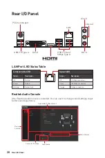
Back Panel
Connectors
∙
1x PS/2 keyboard/ mouse combo port
∙
2x USB 2.0 ports
∙
1x DVI-D port
∙
1x HDMI port
∙
4x USB 3.2 Gen 1 5Gbps Type-A ports
∙
1x LAN(RJ45) port
∙
3x audio jacks
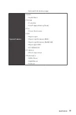
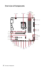
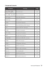
Internal Connectors
∙
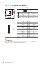
1x 24-pin ATX main power connector
∙
1x 8-pin ATX 12V power connector
∙
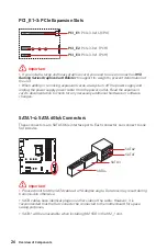
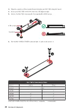
4x SATA 6Gb/s connectors
∙
1x USB 3.2 Gen 1 5Gbps connector (support additional 2
USB 3.2 Gen 1 5Gbps ports)
∙
2x USB 2.0 connectors (support additional 4 USB 2.0 ports)
∙
1x 4-pin CPU fan connector
∙
1x 4-pin water pump connector
∙
2x 4-pin system fan connectors
∙
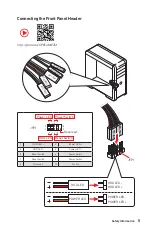
1x front panel audio connector
∙
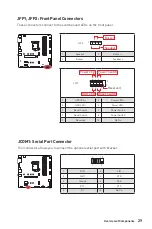
2x system panel connectors
∙
1x parallel port connector
∙
1x serial port connector
∙
1x Chassis Intrusion connector
∙
1x Clear CMOS jumper
∙
1x 4-pin RGB LED connector
∙
1x 3-pin RAINBOW LED connector
∙
1x TPM module connector
LED Feature
∙
4x EZ Debug LED
Continued on next page
Summary of Contents for MAG B460M BAZOOKA
Page 3: ...3 Safety Information Installing a Processor https youtu be 4ce91YC3Oww 1 2 3 6 4 5 7 8 9 ...
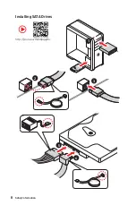
Page 8: ...8 Safety Information Installing SATA Drives http youtu be RZsMpqxythc 1 2 3 4 5 ...
Page 9: ...9 Safety Information 1 Installing a Graphics Card http youtu be mG0GZpr9w_A 2 3 4 5 6 ...
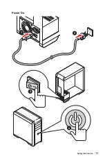
Page 10: ...10 Safety Information Connecting Peripheral Devices ...