Hardaware Setup
2-15
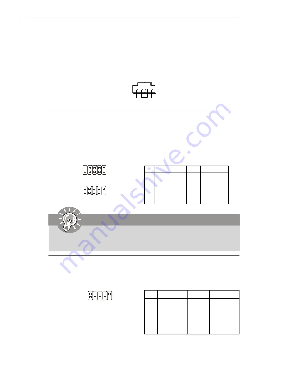
CD-In Connector: JCD1
This connector is provided for CD-ROM audio.
IEEE 1394 Connector: J1394_1 (Optional)
The mainboard provides IEEE1394 pinheader that allow you to connect IEEE 1394 ports
via an external IEEE1394 bracket (optional).
Pin Definition
PIN
SIGNAL
PIN
SIGNAL
1
TPA+
2
TPA-
3
Ground
4
Ground
5
TPB+
6
TPB-
7
Cable power
8
Cable power
9
Key (no pin)
10
Ground
J1394_1
2
1
10
9
JCD1
GND
R
L
Front USB Connectors: JUSB1 & JUSB2
The mainboard provides USB 2.0 pinheaders (optional USB 2.0 bracket available) that
are compliant with Intel
®
I/O Connectivity Design Guide. USB 2.0 technology increases
data transfer rate up to a maximum throughput of 480Mbps, which is 40 times faster
than USB 1.1, and is ideal for connecting high-speed USB interface peripherals such
as
USB HDD
,
digital cameras
,
MP3 players
,
printers
,
modems and the like
.
JUSB2
2
1
10
9
JUSB1
9
10
1
2
PIN
SIGNAL
PIN
SIGNAL
1
VCC
2
VCC
3
USB0-
4
USB1-
5
USB0+
6
USB1+
7
GND
8
GND
9
Key (no pin)
10
USBOC
Pin Definition
Note that the pins of VCC and GND must be connected correctly to
avoid possible damage.
Important
Summary of Contents for Media Live
Page 1: ...Media Live MS 6421 V1 X Media Center G52 64211X2 ...
Page 6: ...vi WEEE Statement ...
Page 7: ...vii ...
Page 8: ...viii ...
Page 84: ...5 2 MS 6421 Media Center Microsoft Windows XP Media Center ...
Page 101: ...5 19 Software Setup Microsoft Windows Vista Media Center ...
Page 170: ...MS 6421 Media Center C 26 ...


