background image

14

전원 켜기

4

4

3

3

1

1

2

2

Summary of Contents for MEG Z790 GODLIKE

Page 1: ...MEG Z790 GODLIKE Motherboard User Guide Benutzerhandbuch Manuel d utilisation...

Page 2: ...English Deutsch Fran ais...

Page 3: ...ont Panel Connectors 46 W_FLOW1 Water Flow Meter Connector 47 JDASH1 Tuning Controller connector 47 CPU_PWR1 2 ATX_PWR1 PD_PWR1 Power Connectors 48 JCI1 Chassis Intrusion Connector 49 POWER1 RESET1 Po...

Page 4: ...RGB LED connector 60 JARGB_V2_1 3 A RAINBOW V2 ARGB Gen2 LED connectors 61 Onboard LEDs 63 EZ Debug LED 63 JPWRLED1 LED power input 63 LED_SW1 EZ LED Control 63 Debug Code LED 64 Boot Phases 64 Debug...

Page 5: ...allations also provide video demonstrations Please link to the URL to watch it with the web browser on your phone or tablet You may have even link to the URL by scanning the QR code Preparing Tools an...

Page 6: ...before installation is completed This could cause permanent damage to the components as well as injury to the user If you need help during any installation step please consult a certified computer te...

Page 7: ...the motherboard circuits and the computer case is prohibited The Case standoff keep out zone signs will be marked on the backside of motherboard as shown below to serve as a warning to user Avoid col...

Page 8: ...6 Installing a Processor https youtu be KMf9oIDsGes 1 1 2 2 3 3 6 6 4 4 5 5 7 7 8 8 9 9...

Page 9: ...7 Installing DDR5 memory https youtu be XiNmkDNZcZk DIMMA2 DIMMA2 DIMMB2 DIMMA1 DIMMA2 DIMMB1 DIMMB2...

Page 10: ...t Panel Header http youtu be DPELIdVNZUI JFP1 HDD LED HDD LED HDD LED POWER LED POWER LED POWER LED R E S E T S W P O W E R S W P O W E R L E D P O W E R L E D H D D L E D 1 2 10 9 Power LED Reserved...

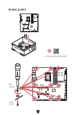
Page 11: ...9 Installing the Motherboard 1 1 https youtu be wWI6Qt51Wnc Torque 3 kgf cm 3 kgf cm 0 3 N m 2 6 lbf in 2 2...

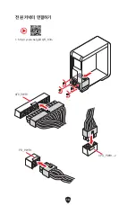
Page 12: ...10 Connecting the Power Connectors http youtu be gkDYyR_83I4 ATX_PWR1 CPU_PWR1 2 PD_PWR1...

Page 13: ...11 Installing SATA Drives http youtu be RZsMpqxythc 1 1 2 2 3 3 4 4 5 5...

Page 14: ...12 Installing a Graphics Card http youtu be mG0GZpr9w_A 1 1 2 2 3 3 4 4 5 5 6 6...

Page 15: ...13 Connecting Peripheral Devices...

Page 16: ...14 Power On 4 4 3 3 1 1 2 2...

Page 17: ...to 6600 MHz 2DPC 1R Max speed up to 6400 MHz 2DPC 2R Max speed up to 5600 MHz Supports Intel XMP 3 0 OC Supports Dual Controller Dual Channel mode Supports non ECC un buffered memory Please refer to w...

Page 18: ...with USB 3 2 devices Supports up to 5V 3A 15W power charging Each port can daisy chain up to three Thunderbolt 4 devices or five Thunderbolt 3 devices Supports up to 8K display need to connect the Dis...

Page 19: ...Ie 4 0 x4 Supports 2260 2280 storage devices PCI_E2 slot will be unavailable when installing M 2 SSD in the M2_4 slot SATA_5 8 will be unavailable when installing M 2 PCIe SSD in the M2_5 slot SATA_7...

Page 20: ...pply unit Internal USB Connectors 2x USB 3 2 Gen 2x2 20Gbps Type C front panel ports From Z790 chipset JUSB6 supports USB PD 60W fast charging 2x USB 3 2 Gen 1 5Gbps connectors From GL3523 Supports ad...

Page 21: ...4 pin RGB LED connector 3x 3 pin A RAINBOW V2 ARGB Gen2 LED connectors 4x EZ Debug LED 1x 2 Digit Debug Code LED Back Panel Connectors 1x Clear CMOS button 1x Flash BIOS button 1x Smart button 2x LAN...

Page 22: ...PU System Pump fan speed control Form Factor E ATX Form Factor 12 in x 12 2 in 305 mm x 310 mm BIOS Features Dual BIOS 2x 256 Mb flash UEFI AMI BIOS ACPI 6 4 SMBIOS 3 5 Multi language Software Drivers...

Page 23: ...ers CPU PUMP SYSTEM Performance Core Boost VRM Power Design VCPU VGT AUX Dual CPU Power OC Engine Memory Boost Memory Force Lightning Gen 5 PCI E M 2 Slot Lightning Gen 4 M 2 Slot Multi GPU Support Th...

Page 24: ...rs utilities Cables 3x SATA 6Gb s cables 1x JRGB extension cable 1 to 2 1x JARGB extension cable 1x JARGB_V2 extension cable 1 to 3 2x Thermistor cables 2x DP to Mini DP cables 1x Front panel cable 1x...

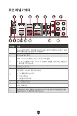
Page 25: ...2 5 Gbps LAN port 3 USB 3 2 Gen 2 10Gbps Type A port From Z790 chipset M Vision Dashboard port Please refer to page 60 for details about connecting M Vision Dashboard 4 10 Gbps LAN port 5 Thunderbolt...

Page 26: ...trol switch turns OFF Safe Boot press and hold the smart button and start the system simultaneously to boot in Safe Boot mode The system will boot with default and lower the PCIe from CPU mode Turbo F...

Page 27: ...reen For 10Gb LAN Linked Blinking Data activity Speed LED Status 2 5Gb LAN Speed 10Gb LAN Speed Off 10 Mbps Green 100 Mbps 1 Gbps 100 Mbps 1 Gbps 2 5 Gbps Orange 2 5 Gbps Yellow 10 Gbps Audio Jacks Co...

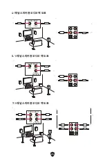
Page 28: ...1 channel speakers diagram Audio jacks to 4 channel speakers diagram Audio jacks to 5 1 channel speakers diagram AUDIO INPUT Rear Front AUDIO INPUT Rear Front Center Subwoofer AUDIO INPUT Rear Front S...

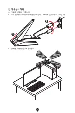
Page 29: ...27 Installing Antennas 1 Combine the antenna with the base 2 Screw two antenna cables tight to the WiFi antenna connectors as shown 1 1 2 2 3 Place the antenna as high as possible...

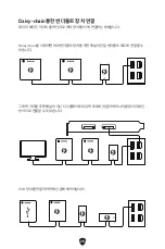
Page 30: ...one output terminal Daisy chain allows you to connect multiple thunderbolt devices to a single thunderbolt port on the back panel You can also daisy chain monitor by connecting graphics card to the M...

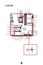
Page 31: ...A2 JARGB_V2_2 JFP2 Processor Socket CPU_PWR1 CPU_PWR2 JFP1 JSLOW1 JLN1 JOC_FS1 SYS_FAN7 LED_SW1 JLN2 JOC_RT1 JBAT1 RESET1 JSMB1 POWER1 JUSB1 M_SW1 JUSB2 T_SEN1 T_SEN2 JDASH1 JTPM1 SYS_FAN4 SYS_FAN6 SY...

Page 32: ...ween the CPU and the heatsink to enhance heat dissipation Whenever the CPU is not installed always protect the CPU socket pins by covering the socket with the plastic cap If you purchased a separate C...

Page 33: ...ing due to the memory frequency operates dependent on its Serial Presence Detect SPD Go to BIOS and find the DRAM Frequency to set the memory frequency if you want to operate the memory at the marked...

Page 34: ...on card installation with optimum performance using the PCI_E1 slot is recommended When adding or removing expansion cards always turn off the power supply and unplug the power supply power cable from...

Page 35: ...remove the M 2 plate or rubber cube in the M 2 slot before installing M 2 SSD Do not re install the heatsink supplied with your motherboard Installing M 2 module into M2_1 slot 1 Press and hold the e...

Page 36: ...move it forward to uninstall the heatsink 2 2 3 Remove the protective film includeing the rubber cube from the M 2 thermal pads on the M 2 plate 3 3 4 Remove or exchange the screws according to your...

Page 37: ...22110 SSD 2280 SSD 2260 SSD 7 Remove the protective films from the thermal pads under Screwless M 2 Shield Frozr heatsink 8 Align the tenons under Screwless M 2 Shield Frozr heatsink with the notches...

Page 38: ...Shield Frozr heatsink up and remove it 1 1 1 1 1 1 1 1 2 2 3 Remove the protective films from the M 2 thermal pads on the M 2 plate 3 3 4 If you install 2260 SSD remove the screw from the M 2 plate an...

Page 39: ...6 Rotate the EZ M 2 Clip to fix the M 2 SSD 30 30 30 30 2280 SSD 2260 SSD 6 6 5 5 5 5 6 6 7 Remove the protective films from the thermal pads under the M 2 Shield Frozr heatsink 8 Put the M 2 Shield...

Page 40: ...module into M2_4 M2_5 slot 1 Loosen the screws of M 2 Shield Frozr heatsink 2 Lift the M 2 Shield Frozr heatsink up and remove it 1 1 1 1 2 2 3 Remove the protective films from the M 2 thermal pads on...

Page 41: ...ove it first otherwise please skip this step 5 Install the supplied EZ M 2 Clip kit on the M 2 plate according to your M 2 SSD length 4 4 5 5 6 Insert your M 2 SSD into the M 2 slot at a 30 degree ang...

Page 42: ...40 Ways to install M2_4 M2_5 22110 SSD 2260 SSD 2280 SSD 2280 SSD...

Page 43: ...41 8 Remove the protective films from the thermal pads under the M 2 Shield Frozr heatsink 9 Put the M 2 Shield Frozr heatsink back in place and secure it 9 9 9 9 8 8...

Page 44: ...tton of Screwless M 2 Shield Frozr heatsink 1 1 2 Slightly lift up the end part of Screwless M 2 Shield Frozr heatsink and move it forward to uninstall the heatsink 2 2 3 Remove the protective film in...

Page 45: ...late and then install supplied EZ M 2 Clip kit on the M 2 plate Skip this step if you install 2280 SSD 4 4 2260 SSD 5 Insert your M 2 SSD into the M 2 slot at a 30 degree angle 6 Rotate the EZ M 2 Cli...

Page 46: ...under Screwless M 2 Shield Frozr heatsink 8 Align the tenons under Screwless M 2 Shield Frozr heatsink with the notches and then put the heatsink back in place 9 Press the end side of Screwless M 2 S...

Page 47: ...er sides of the cable However it is recommended that the flat connector be connected to the motherboard for space saving purposes SATA_5 8 will be unavailable when installing M 2 PCIe SSD in the M2_5...

Page 48: ...cates the activity of the hard disk The JFP2 connector is for Buzzer and Speaker To connect the cables from PC case to the right pins please refer to the following images below 1 2 10 9 Power LED Rese...

Page 49: ...1 No Pin 2 NC 3 MCU_SMB_SCL_M 4 MCU_SMB_SDA_M 5 VCC5 6 Ground 7 PSIN _R 8 FP_RST _R 9 OC_RETRY 10 OC_FS 11 BLK 12 BLK 13 CLRCMOS_EN 14 NC Pin Signal Name Pin Signal Name 1 Ground 2 WFLOW PWR 3 WFLOW...

Page 50: ...needs to be connected to the power supply unit CPU_PWR1 2 Pin Signal Name Pin Signal Name 1 Ground 2 Ground 3 Ground 4 Ground 5 12V 6 12V 7 12V 8 12V PD_PWR1 Pin Signal Name Pin Signal Name 1 12v 2 12...

Page 51: ...Chassis Intrusion to Enabled 5 Press F10 to save and exit and then press the Enter key to select Yes 6 Once the chassis cover is opened again a warning message will be displayed on screen when the co...

Page 52: ...of design When you connect the cable be sure to connect it with the corresponding orientation JUSB5 6 USB Type C Cable USB Type C port on the front panel Pin Signal Name Pin Signal Name 1 Power 2 USB3...

Page 53: ...TPM1 TPM Module Connector This connector is for TPM Trusted Platform Module Please refer to the TPM security platform manual for more details and usages Pin Signal Name Pin Signal Name 1 VCC 2 VCC 3 U...

Page 54: ...POST Normal Default Important Please note that overclocking at an extremely low temperature carries the risk of system instability and may cause damages to the system The overclocking results may var...

Page 55: ...items until it boot up successfully Normal default Boot with the saved BIOS settings Normal default Enabled Apply the BIOS default settings and lower PCIe from CPU mode for Safe Boot Retry OC JOC_FS1...

Page 56: ...OS switch when system is booting up You can also use the MSI Center or Flash BIOS Button to flash BIOS Please refer to BIOS section for details BIOS B BIOS A Default T_SEN1 2 Thermal Sensor Connector...

Page 57: ...t Fan Mode the fan speed will change according to the CPU or system temperature Uncheck the Smart Fan Mode the fan will spin at maximum speed Important Make sure fans are working properly after switch...

Page 58: ...er cord 2 Use a jumper cap to short JBAT1 for about 5 10 seconds 3 Remove the jumper cap from JBAT1 4 Plug the power cord and Power on the computer V Check Points Lite These voltage checkpoints are us...

Page 59: ...nplug the battery wire from the BAT1 connector and remove the battery 2 Connect the new CR2032 battery with wire to the BAT1 connector WARNING KEEP OUT OF REACH OF CHILDREN Swallowing can lead to chem...

Page 60: ...and the M Vision mode Features on M Vision Dashboard 4 5 inch IPS LCD panel resistive single touch Full color display 480x 800 Touch control USB Type C connection Speaker function Landscape portrait...

Page 61: ...nnect the M Vision Dashboard and specified USB port M Vision Dashboard port on the back panel 2 Switch the M Vision switch M_SW1 to the M Vision mode 1 1 1 1 2 2 M Vision Dashboard port M Vision cable...

Page 62: ...re installing or removing the RGB LED strip Please use MSI s software to control the extended LED strip JRGB1 RGB LED connector The JRGB connector allows you to connect the 5050 RGB LED strips 12V 1 G...

Page 63: ...upports up to 240 individually addressable RGB LEDs with maximum power rating of 3A 5V Pin Signal Name Pin Signal Name 1 5V 2 Data 3 No Pin 4 Ground 1 1 1 1 1 D 5V JARGB_V2 connector JARGB_V2 connecto...

Page 64: ...B Gen1 and ARGB Gen2 LED strips into the same connector it may cause some issues Please do not mix the ARGB Gen1 LED and the ARGB Gen2 LED strips together It is recommended that you install LED strips...

Page 65: ...trate onboard LED lights JPWRLED1 LED power input LED_SW1 EZ LED Control This switch is used to switch on off all the LEDs of motherboard LED_SW1 LED_OFF LED_ON Default CPU indicates CPU is not detect...

Page 66: ...ode LED Table SEC Progress Codes 01 Power on Reset type detection soft hard 02 AP initialization before microcode loading 03 System Agent initialization before microcode loading 04 PCH initialization...

Page 67: ...ng memory 2F Memory initialization other 31 Memory Installed 32 CPU post memory initialization is started 33 CPU post memory initialization Cache initialization 34 CPU post memory initialization Appli...

Page 68: ...ror codes DXE Progress Codes 60 DXE Core is started 61 NVRAM initialization 62 Installation of the PCH Runtime Services 63 CPU DXE initialization is started 64 67 CPU DXE initialization CPU module spe...

Page 69: ...es connect 98 Console input devices connect 99 Super IO Initialization 9A USB initialization is started 9B USB Reset 9C USB Detect 9D USB Enable 9E 9F Reserved for future AMI codes A0 IDE initializati...

Page 70: ...ation error D3 Some of the Architectural Protocols are not available D4 PCI resource allocation error Out of Resources D5 No Space for Legacy Option ROM D6 No Console Output Devices are found D7 No Co...

Page 71: ...Recovery firmware image is loaded F5 F7 Reserved for future AMI progress codes Recovery Error Codes F8 Recovery PPI is not available F9 Recovery capsule is not found FA Invalid recovery capsule FB FF...

Page 72: ...the S4 sleep state AC System has transitioned into ACPI mode Interrupt controller is in PIC mode AA System has transitioned into ACPI mode Interrupt controller is in APIC mode CPU Temperature 00 99 D...

Page 73: ...xe to open the installer If you turn off the AutoPlay feature from the Windows Control Panel you can still manually execute the DVDSetup exe from the root path of the MSI USB Drive 4 The installer wil...

Page 74: ...bilities of new devices new devices may not provide backward compatibility Supports secure startup UEFI can check the validity of the operating system to ensure that no malware tampers with the startu...

Page 75: ...ter Boot Menu message appears on the screen during the boot process Function key F1 General Help list F2 Add Remove a favorite item F3 Enter Favorites menu F4 Enter CPU Specifications menu F5 Enter Me...

Page 76: ...ite And then save the BIOS file into the USB flash drive Updating BIOS 1 Switch to the target BIOS ROM by Multi BIOS switch Please skip this step if your motherboard doesn t has this switch 2 Insert t...

Page 77: ...m will automatically restart to update BIOS 6 After the flashing process is 100 completed the system will restart automatically Updating BIOS with Flash BIOS Button 1 Please download the latest BIOS f...

Page 78: ...schl sse 46 W_FLOW1 Anschluss des Wasserdurchflusssensors 47 JDASH1 Tuning Controller Anschluss 47 CPU_PWR1 2 ATX_PWR1 PD_PWR1 Stromanschl sse 48 JCI1 Geh usekontaktanschluss 49 POWER1 RESET1 Power Ta...

Page 79: ...B1 RGB LED Anschluss 60 JARGB_V2_1 3 A RAINBOW V2 ARGB Gen2 LED Anschl sse 61 Onboard LEDs 63 EZ DEBUG LED 63 JPWRLED1 LED Stromzufuhr 63 LED_SW1 EZ LED Steuerung 63 Debug Code LED 64 Boot Phasen 64 D...

Page 80: ...ie Videodemonstrationen Klicken Sie auf die URL um diese Videoanleitung mit Ihrem Browser auf Ihrem Handy oder Table anzusehen Oder scannen Sie auch den QR Code mit Ihrem Handy um die URL zu ffnen Wer...

Page 81: ...t bevor die Installation abgeschlossen ist Dies k nnte permanente Sch den an den Komponenten sowie zu das Verletzung des Benutzers verursachen Sollten Sie Hilfe bei der Installation ben tigen wenden S...

Page 82: ...tkreisen und dem Computergeh use verboten Die Schilder Case Standoff Keep Out Zone Geh useabstandszone freihalten auf der R ckseite des Motherboards wie unten gezeigt dienen als entsprechender Hinweis...

Page 83: ...6 Installation des Prozessors https youtu be KMf9oIDsGes 1 1 2 2 3 3 6 6 4 4 5 5 7 7 8 8 9 9...

Page 84: ...7 Installation des DDR5 Speichers https youtu be XiNmkDNZcZk DIMMA2 DIMMA2 DIMMB2 DIMMA1 DIMMA2 DIMMB1 DIMMB2...

Page 85: ...anel Stiftleiste http youtu be DPELIdVNZUI JFP1 HDD LED HDD LED HDD LED POWER LED POWER LED POWER LED R E S E T S W P O W E R S W P O W E R L E D P O W E R L E D H D D L E D 1 2 10 9 Power LED Reserve...

Page 86: ...9 Installation des Motherboards 1 1 https youtu be wWI6Qt51Wnc Drehmoment 3 kgf cm 3 kgf cm 0 3 N m 2 6 lbf in 2 2...

Page 87: ...10 Stromanschl sse anschliessen http youtu be gkDYyR_83I4 ATX_PWR1 CPU_PWR1 2 PD_PWR1...

Page 88: ...11 Installation der SATA Laufwerke http youtu be RZsMpqxythc 1 1 2 2 3 3 4 4 5 5...

Page 89: ...12 Einbau der Grafikkarte http youtu be mG0GZpr9w_A 1 1 2 2 3 3 4 4 5 5 6 6...

Page 90: ...13 Peripherieger te...

Page 91: ...14 Einschalten 4 4 3 3 1 1 2 2...

Page 92: ...raten bis zu 6400 MHz 2DPC 2R max bertragungsraten bis zu 5600 MHz Unterst tzt Intel XMP 3 0 OC Unterst tzt den Dual Controller Zweikanalmodus Unterst tzt non ECC ungepufferte Speicher Weitere Informa...

Page 93: ...A und die Ladeleistung bis zu 15W Jeder Anschluss kann bis zu drei Thunderbolt 4 Ger te oder f nf Thunderbolt 3 Ger te verketten Unterst tzt bis zu 8K Display muss den DisplayPort des Motherboards od...

Page 94: ...Der PCI_E2 Anschluss wird nicht zur Verf gung stehen wenn Sie eine M 2 SSD im M2_4 Steckplatz installieren SATA_5 8 Anschl sse werden nicht zur Verf gung stehen wenn Sie eine M 2 SATA SSD im M2_5 Ste...

Page 95: ...Anschl sse 2x USB 3 2 Gen 2x2 20Gbit s Typ C Frontplattenanschl sse vom Z790 Chipsatz JUSB6 unterst tzt USB PD 60W Schnellladung 2x USB 3 2 Gen 1 5Gbit s Anschl sse vom GL3523 Unterst tzt zus tzliche...

Page 96: ...halter LED Funktionen 1x 4 poliger RGB LED Anschluss 3x 3 polige A RAINBOW V2 ARGB Gen2 LED Anschl sse 4x EZ Debug LED 1x 2 Digit Debug Code LED Hintere Ein und Ausg nge 1x Clear CMOS Taste 1x Flash B...

Page 97: ...System Pump L fter Drehzahlregelung Formfaktor E ATX Formfaktor 12 Zoll x 12 2 Zoll 305 mm x 310 mm BIOS Funktionen Dual BIOS 2x 256 Mb Flash UEFI AMI BIOS ACPI 6 4 SMBIOS 3 5 Mehrsprachenunterst tzun...

Page 98: ...U PUMP SYSTEM Leistung Core Boost VRM Power Design VCPU VGT AUX Dual CPU Power OC Engine Memory Boost Memory Force Lightning Gen 5 PCI E M 2 Steckplatz Lightning Gen 4 M 2 Steckplatz Multi GPU Unterst...

Page 99: ...mmen Kabel 3x SATA 6Gb s Kabel 1x JRGB Verl ngerungskabel 1 zu 2 1x JARGB Verl ngerungskabel 1x JARGB V2 Verl ngerungskabel 1 zu 3 2x Temperaturf hler Kabel 2x DP zu Mini DP Kabel 1x Frontpanel Kabel...

Page 100: ...nschluss 3 USB 3 2 Gen 2 10Gbit s Typ A Anschluss vom Z790 Chipsatz Anschluss f r M Vision Dashboard Auf der Seite 60 finden Sie weitere Informationen zum Anschluss von M Vision Dashboard 4 10 Gbit s...

Page 101: ...Boot Halten Sie die Taste gedr ckt und starten Sie das System gleichzeitig um im abgesicherten Startmodus zu starten Das System startet mit den Standardeinstellungen und senkt den PCIe Modus von der C...

Page 102: ...LAN Verbindung Blinkt Datenaktivit t Geschwindigkeit LED Zustand 2 5Gb LAN Anschl sse 10Gb LAN Anschl sse Off Aus 10 Mbit s Gr n 100 Mbit s 1 Gbit s 100 Mbit s 1 Gbit s 2 5 Gbit s Orange 2 5 Gbit s G...

Page 103: ...diobuchsen f r 7 1 Kanal Anlage Audiobuchsen f r 4 Kanal Anlage Audiobuchsen f r 5 1 Kanal Anlage AUDIO INPUT Rear Front AUDIO INPUT Rear Front Center Subwoofer AUDIO INPUT Rear Front Side Center Subw...

Page 104: ...Antennen installieren 1 Verbinden Sie Antenne mit dem Antennenfu 2 Schrauben Sie wie gezeigt die Antennen fest an die Wi Fi Antennenanschl sse 1 1 2 2 3 Positionieren Sie die Antennen so hoch wie m gl...

Page 105: ...aisy Chain k nnen Sie h chstens mehrere Thunderbolt Ger te an einen einzelnen Thunderbolt Anschluss an der hinteren E A Abdeckung anschlie en Sie k nnen auch 2 Monitore verketten indem Sie die Grafikk...

Page 106: ...2 JARGB_V2_2 JFP2 Prozessor Sockel CPU_PWR1 CPU_PWR2 JFP1 JSLOW1 JLN1 JOC_FS1 SYS_FAN7 LED_SW1 JLN2 JOC_RT1 JBAT1 RESET1 JSMB1 POWER1 JUSB1 M_SW1 JUSB2 T_SEN1 T_SEN2 JDASH1 JTPM1 SYS_FAN4 SYS_FAN6 SYS...

Page 107: ...rper vorhanden ist um die W rmeableitung zu erh hen Sch tzen Sie den CPU Sockel immer mit der Plastikabdeckung wenn keine CPU installiert ist Verwenden Sie bitte die Installationsanweisung des K hlk r...

Page 108: ...iten als der festgelegte Wert abh ngig von dem SPD Serial Presence Detect Stellen Sie im BIOS Setup mit DRAM Frequency die Speicherfrequenz ein wenn Sie mit der festgelegten oder einer h heren Speiche...

Page 109: ...tung empfehlen wir den PCI_E1 Steckplatz zu verwenden Achten Sie darauf dass Sie den Strom abschalten und das Netzkabel aus der Steckdose herausziehen bevor Sie eine Erweiterungskarte installieren ode...

Page 110: ...tte und installieren Sie dann die M 2 SSD im M 2 Steckplatz Installieren Sie nicht den mit Ihrem Motherboard gelieferten K hlk rper Installieren des M 2 Moduls im M2_1 Steckplatz 1 Dr cken und halten...

Page 111: ...lk rper zu deinstallieren 2 2 3 Entfernen Sie die Schutzfolie einschlie lich des Gummiw rfels von den M 2 W rmeleitpadsthe des M 2 K hlk rpers 3 3 4 Entfernen oder tauschen Sie die Schrauben entsprech...

Page 112: ...2260 SSD 7 Entfernen Sie die Schutzfolie von den W rmeleitpads unter dem schraublosen M 2 Shield Frozr K hlk rper 8 Richten Sie die Zapfen unter dem schraublosen M 2 Shield Frozr K hlk rper an den Ke...

Page 113: ...und entfernen Sie ihn 1 1 1 1 1 1 1 1 2 2 3 Entfernen Sie die Schutzfolie von den M 2 W rmeleitpadsthe des M 2 K hlk rpers 3 3 4 Wenn Sie 2260 SSD installieren entfernen Sie die Schraube von der M 2 P...

Page 114: ...Sie den EZ M 2 Clip um die M 2 SSD zu befestigen 30 30 30 30 2280 SSD 2260 SSD 6 6 5 5 5 5 6 6 7 Entfernen Sie die Schutzfolie vom W rmeleitpad unter dem M 2 Shield Frozr K hlk rper 8 Setzen Sie den...

Page 115: ...r M2_5 Steckplatz 1 L sen Sie die Schraube des M 2 SHIELD FROZR K hlk rpers 2 Heben Sie den M 2 Shield Frozr K hlk rper an und entfernen Sie ihn 1 1 1 1 2 2 3 Entfernen Sie die Schutzfolie von den M 2...

Page 116: ...diesen Schritt 5 Wenn kein EZ M 2 Clip Kit installiert ist installieren Sie bitte das mitgelieferte EZ M 2 Clip Kit entsprechend Ihrer M 2 SSD L nge im M 2 Steckplatz 4 4 5 5 6 Stecken Sie eine M 2 SS...

Page 117: ...40 M glichkeiten zur Installation von M2_4 M2_5 22110 SSD 2260 SSD 2280 SSD 2280 SSD...

Page 118: ...41 8 Entfernen Sie die Schutzfolie vom W rmeleitpad unter dem M 2 Shield Frozr K hlk rper 9 Setzen Sie den M 2 SHIELD FROZR K hlk rper wieder ein und sichern Sie ihn 9 9 9 9 8 8...

Page 119: ...hraublosen M 2 Shield Frozr K hlk rpers 1 1 2 Heben Sie das Ende des schraublosen M 2 Shield Frozr K hlk rpers leicht an und bewegen Sie ihn nach vorne um den K hlk rper zu deinstallieren 2 2 3 Entfer...

Page 120: ...n das mitgelieferte EZ M 2 Clip Kit auf der M 2 Platte berspringen Sie diesen Schritt wenn Sie eine 2280 SSD installieren 4 4 2260 SSD 5 Stecken Sie eine M 2 SSD im 30 Grad Winkel in den M 2 Steckplat...

Page 121: ...Shield Frozr K hlk rper 8 Richten Sie die Zapfen unter dem schraublosen M 2 Shield Frozr K hlk rper an den Kerben aus und setzen Sie den K hlk rper dann wieder ein 9 Dr cken Sie die Endseite des schra...

Page 122: ...Es wird empfohlen den flachen Stecker auf dem Motherboard einstecken SATA_5 8 Anschl sse werden nicht zur Verf gung stehen wenn Sie eine M 2 PCIe SSD im M2_5 Steckplatz installieren SATA_7 8 Anschl ss...

Page 123: ...an Der JFP2 Anschluss ist f r den Signaltongeber und Lautsprecher vorgesehen Um die Kabel vom PC Geh use an die richtigen Pins anzuschlie en sehen Sie sich bitte die folgenden Bilder an 1 2 10 9 Powe...

Page 124: ...U_SMB_SCL_M 4 MCU_SMB_SDA_M 5 VCC5 6 Ground 7 PSIN _R 8 FP_RST _R 9 OC_RETRY 10 OC_FS 11 BLK 12 BLK 13 CLRCMOS_EN 14 NC Pin Signalname Pin Signalname 1 Ground 2 WFLOW PWR 3 WFLOW IN W_FLOW1 Anschluss...

Page 125: ...s der PD_PWR1 Anschluss an das Netzteil angeschlossen werden CPU_PWR1 2 Pin Signalname Pin Signalname 1 Ground 2 Ground 3 Ground 4 Ground 5 12V 6 12V 7 12V 8 12V PD_PWR1 Pin Signalname Pin Signalname...

Page 126: ...ern und Beenden und dr cken Sie dann die Enter Taste um Ja auszuw hlen 6 Bei eingeschaltetem Computer wird eine Warnmeldung auf dem Bildschirm angezeigt wenn die Geh useabdeckung wieder ge ffnet wird...

Page 127: ...hluss verf gt ber ein besonders sicheres Design Wenn Sie das Kabel anschlie en m ssen Sie es in der entsprechenden Ausrichtung verbinden JUSB5 6 USB Typ C Kabel USB Typ C Anschluss auf dem Frontpanel...

Page 128: ...MSI Center Dienstprogramm JTPM1 TPM Anschluss Dieser Anschluss wird f r das TPM Modul Trusted Platform Module verwendet Weitere Informationen ber den Einsatz des optionalen TPM Modules entnehmen Sie b...

Page 129: ...bertaktung bei einer extrem niedrigen Temperatur das Risiko einer Systeminstabilit t birgt und Sch den am System verursachen kann Die bertaktungsergebnisse k nnen je nach verwendeter CPU variieren Akt...

Page 130: ...al Standardwert Booten Sie mit den gespeicherten BIOS Einstellungen Normal Standardwert Aktiviert Wenden Sie die BIOS Standardeinstellungen und den niedrigeren PCIe Modus von der CPU f r den sicheren...

Page 131: ...rwenden Sie den Multi BIOS Schalter nicht Sie k nnen auch MSI Center oder Flash BIOS Taste verwenden um das BIOS zu flashen Weitere Informationen finden Sie im Abschnitt Aufrufen des BIOS Setups BIOS...

Page 132: ...instellen W hlen Sie den Smart Fan Mode die L ftergeschwindigkeit ndert sich entsprechend der CPU oder Systemtemperatur Deaktivieren Sie den Smart Fan Mode der L fter dreht sich mit maximaler Geschwin...

Page 133: ...n Sie eine Steckbr cke um JBAT1 f r 5 10 Sekunden kurzzuschlie en 3 Entfernen Sie die Steckbr cke von JBAT1 4 Stecken Sie das Kabel Ihres Computers in die Steckdose hinein und schalten Sie den Compute...

Page 134: ...riekabel vom BAT1 Anschluss und entfernen Sie die Batterie 2 Schlie en Sie die neue CR2032 Batterie mit Kabel an den BAT1 Anschluss an WARNUNG F r Kinder unzug nglich aufbewahren Das Verschlucken kann...

Page 135: ...dem M Vision Modus umschalten Funktionen von M Vision Dashboard 4 5 Zoll IPS LCD Display resistiver Single Touch Vollfarb Display 480x 800 Touch Bedienung USB Typ C Anschluss Lautsprecher Funktion Qu...

Page 136: ...ISION Dashboard und den angegebenen USB Anschluss M Vision Dashboard Anschluss auf der R ckseite zu verbinden 2 Schalten Sie den M Vision Schalter M_SW1 auf M Vision Modus 1 1 1 1 2 2 M Vision Dashboa...

Page 137: ...in und ausbauen Bitte verwenden Sie die MSI Software zur Steuerung des LED Leuchtstreifens JRGB1 RGB LED Anschluss Mit dem JRGB Anschluss k nnen Sie den 5050 RGB LED Streifen 12 V anschlie en 1 G R B...

Page 138: ...bis zu 240 einzeln adressierbare RGB LEDs mit einer maximalen Nennleistung von 3 A 5 V Pin Signalname Pin Signalname 1 5V 2 Data 3 No Pin 4 Ground 1 1 1 1 1 D 5V JARGB_V2 Anschluss JARGB_V2 Anschluss...

Page 139: ...RGB Gen2 LED Streifen an denselben Anschluss anschlie en kann dies unter Umst nden Probleme verursachen Bitte verwenden Sie ARGB Gen1 LED und ARGB Gen2 LED Streifen nicht miteinander Es wird empfohlen...

Page 140: ...hteffekte zu zeigen JPWRLED1 LED Stromzufuhr LED_SW1 EZ LED Steuerung Mit diesem Schalter werden alle LEDs des Motherboards ein und ausgeschaltet LED_SW1 LED_AUS LED_EIN Standardwert CPU CPU wird nich...

Page 141: ...ebug Code LED Tabelle SEC Fortschritt Codes 01 Computerstart Reset Typ Erkennung Soft Hard Reset 02 AP Initialisierung vor dem Mikrocode Ladevorgang 03 AP Initialisierung vor dem Mikrocode Ladevorgang...

Page 142: ...ung Programmierung des Speicher Timings 2E Speicher Initialisierung Konfiguration des Speichers 2F Speicher Initialisierung sonstige 31 Speicher ist installiert 32 CPU Post Memory Initialisierung wird...

Page 143: ...hwindigkeit 57 Inkompatibilit t der CPU 58 Der CPU Selbsttest ist fehlgeschlagen oder es liegt ein CPU Cache Fehler vor 59 CPU Micro Code wurde nicht gefunden oder das Updaten des Micro Codes ist fehl...

Page 144: ...et 92 PCI Bus Initialisierung wird gestartet 93 PCI Bus Hot Plug Controller Initialisierung 94 PCI Bus Enumeration 32 95 PCI Bus Request Resources 96 PCI Bus Assign Resources 97 Verbindung der Konsole...

Page 145: ...n ROM Initialisierung B3 System R cksetzung B4 USB Hot Plug B5 PCI Bus Hot Plug B6 NVRAM aufr umen B7 Setzt die Konfiguration zur ck setzt die NVRAM Einstellungen zur ck B8 BF Reserviert f r zuk nftig...

Page 146: ...E7 Reserviert f r zuk nftige AMI Fortschrittscodes S3 Wiederaufnahme Fehler Codes E8 Das S3 Wiederaufnehmen ist fehlgeschlagen E9 Das S3 Wiederaufnehmen PPI wurde nicht gefunden EA Boot Skript Fehler...

Page 147: ...Ruhezustand S2 03 Das System geht in den Ruhezustand S3 04 Das System geht in den Ruhezustand S4 05 Das System geht in den Ruhezustand S5 10 Das System beendet den Ruhezustand S1 20 Das System beendet...

Page 148: ...iesen Schritt 7 Folgen Sie den Anweisungen auf dem Bildschirm um das Dienstprogramm Windows 10 Windows 11 zu installieren Installation von Treibern 1 Starten Sie Ihren Computer mit Windows 10 Windows...

Page 149: ...und anderen MSI Produkten steuern und synchronisieren Mit MSI Center k nnen Sie ideale Modi einstellen die Systemleistung berwachen und die L ftergeschwindigkeit anpassen MSI Center Benutzerhandbuch...

Page 150: ...ionen Unterst tzt den vollen Funktionsumfang neuer Ger te neue Ger te bieten m glicherweise keine Abw rtskompatibilit t Unterst tzt sicheren Start UEFI kann die G ltigkeit des Betriebssystems berpr fe...

Page 151: ...p Menu F11 to enter Boot Menu erscheint Funktionstasten F1 Allgemeine Hilfe F2 Hinzuf gen Entfernen eines Favoritenpunkts F3 ffnen des Favoriten Men s F4 ffnen des Men s CPU Spezifikationen F5 ffnen d...

Page 152: ...BIOS Datei auf USB Flash Laufwerk BIOS Aktualisierungsschritte 1 Wechseln Sie mit dem Multi BIOS Switch zum Ziel BIOS ROM berspringen Sie diesen Schritt wenn Ihr Motherboard diesen Schalter nicht hat...

Page 153: ...startet um das BIOS zu aktualisieren 6 Nachdem das Flashen des BIOS vollst ndig ist startet das System automatisch neu Aktualisierung des BIOS mit Flash BIOS Taste 1 Laden Sie bitte die neueste BIOS V...

Page 154: ...onnecteur de d bitm tre d eau 47 JDASH1 Connecteur du contr leur de r glages 47 CPU_PWR1 2 ATX_PWR1 PD_PWR1 Connecteurs d alimentation 48 JCI1 Connecteur d intrusion ch ssis 49 POWER1 RESET1 Bouton d...

Page 155: ...teurs LED A RAINBOW V2 ARGB Gen2 61 LED embarqu es 63 EZ Debug LED 63 JPWRLED1 Indicateur LED de l entr e d alimentation 63 LED_SW1 Contr le EZ LED 63 Debug Code LED 64 Phase de d marrage 64 Tableau d...

Page 156: ...galement des d monstrations vid o Veuillez visiter l URL pour regarder la vid o sur le navigateur Web de votre t l phone ou de votre tablette Vous pouvez galement visiter l URL en scannant le code QR...

Page 157: ...s sur la carte m re ou ailleurs dans le bo tier de l ordinateur Ne d marrez pas l ordinateur avant d avoir termin l installation Ceci peut endommager les composants ou vous blesser Si vous avez besoi...

Page 158: ...entre le circuit de la carte m re et le bo tier de l ordinateur Les signes de zone interdite Keep Out Zone sont marqu s l arri re de la carte m re comme indiqu ci dessous pour servir d avertissement...

Page 159: ...6 Installation d un processeur https youtu be KMf9oIDsGes 1 1 2 2 3 3 6 6 4 4 5 5 7 7 8 8 9 9...

Page 160: ...7 Installation de la m moire DDR5 https youtu be XiNmkDNZcZk DIMMA2 DIMMA2 DIMMB2 DIMMA1 DIMMA2 DIMMB1 DIMMB2...

Page 161: ...neau avant http youtu be DPELIdVNZUI JFP1 HDD LED HDD LED HDD LED POWER LED POWER LED POWER LED R E S E T S W P O W E R S W P O W E R L E D P O W E R L E D H D D L E D 1 2 10 9 Power LED Reserved Powe...

Page 162: ...9 Installation de la carte m re 1 1 https youtu be wWI6Qt51Wnc Torque 3 kgf cm 3 kgf cm 0 3 N m 2 6 lbf in 2 2...

Page 163: ...10 Connexion des connecteurs d alimentation http youtu be gkDYyR_83I4 ATX_PWR1 CPU_PWR1 2 PD_PWR1...

Page 164: ...11 Installation des disques SATA http youtu be RZsMpqxythc 1 1 2 2 3 3 4 4 5 5...

Page 165: ...12 Installation d une carte graphique http youtu be mG0GZpr9w_A 1 1 2 2 3 3 4 4 5 5 6 6...

Page 166: ...13 Connexion des p riph riques...

Page 167: ...14 Allumer 4 4 3 3 1 1 2 2...

Page 168: ...nte jusqu 6600 MHz La fr quence maximale en mode 2DPC 1R monte jusqu 6400 MHz La fr quence maximale en mode 2DPC 2R monte jusqu 5600 MHz Support Intel XMP 3 0 OC Support m moire dual channel double co...

Page 169: ...ues USB 3 2 Support d une alimentation allant jusqu 5 V 3 A et 15 W Chaque port peut connecter la cha ne jusqu trois p riph riques Thunderbolt 4 ou cinq p riph riques Thunderbolt 3 Supporte jusqu cran...

Page 170: ...ort des p riph riques de stockage 2260 2280 Le slot PCI_E2 est indisponible lorsqu un SSD M 2 est install dans le slot M2_4 Les connecteurs SATA_5 8 sont indisponibles lorsqu un SSD M 2 PCIe est insta...

Page 171: ...ge rapide PD 60 watts sur le port USB le connecteur PD_PWR1 doit tre connect au bloc d alimentation Connecteurs USB internes 2 x ports USB 3 2 Gen 2x2 20 Gb s Type C du panneau avant depuis chipset Z7...

Page 172: ...ion 1 x bouton Clear CMOS sur le panneau arri re 1 x bouton Flash BIOS sur le panneau arri re 1 x bouton intelligent sur le panneau arri re Cavalier 1 x cavalier Clear CMOS 1 x cavalier de mode ralent...

Page 173: ...on Thunderbolt 2 x connecteurs d antenne Wi Fi 5 x prises audio OFC 1 x connecteur Sortie S PDIF optique Contr leur E S Contr leur NUVOTON NCT6687 R Moniteur syst me D tection de la temp rature CPU Sy...

Page 174: ...aders CPU PUMP SYSTEM Performance Core Boost VRM Power Design VCPU VGT AUX Dual CPU Power OC Engine Memory Boost Memory Force Lightning Gen 5 PCI E M 2 Slot Lightning Gen 4 M 2 Slot Multi GPU Support...

Page 175: ...es C ble 3 x c bles SATA 6 Gb s 1 x c ble d extension JRGB 1 vers 2 1 x c ble d extension JARGB 1 x c ble d extension JARGB_V2 1 vers 3 2 x c bles thermistance 2 x c bles DP vers Mini DP 1 x c ble de...

Page 176: ...t LAN 2 5 Gb s 3 Port USB 3 2 Gen 2 10 Gb s Type A depuis chipset Z790 Port M Vision Dashboard Veuillez vous r f rer la page 60 pour savoir comment connecter le M Vision Dashboard 4 Port LAN 10 Gb s 5...

Page 177: ...Z LED est param tr sur OFF D marrage securis appuyez sur le bouton intelligent et maintenez le enfonc pour d marrer le syst me simultan ment en mode de d marrage s curis Le syst me d marrera par d fau...

Page 178: ...Gb Connexion correcte Clignote Activit en cours LED indiquant la vitesse tat Vitesse LAN 2 5 Gb Vitesse LAN 10 Gb teint 10 Mb s Vert 100 Mb s 1 Gb s 100 Mb s 1 Gb s 2 5 Gb s Orange 2 5 Gb s Jaune 10...

Page 179: ...eurs 7 1 canaux Sch ma de connexion des prises audio aux haut parleurs 4 canaux Sch ma de connexion des prises audio aux haut parleurs 5 1 canaux AUDIO INPUT Rear Front AUDIO INPUT Rear Front Center S...

Page 180: ...7 Installation des antennes 1 Combinez l antenne avec la base 2 Vissez fermement les antennes aux connecteurs d antenne Wi Fi comme indiqu ci dessous 1 1 2 2 3 Placez les antennes le plus haut possibl...

Page 181: ...rminal de sortie La connexion en cha ne vous permet de connecter plusieurs p riph riques Thunderbolt un seul port Thunderbolt sur le panneau arri re Vous pouvez galement connecter l cran en connectant...

Page 182: ...ARGB_V2_2 JFP2 Socket processeur CPU_PWR1 CPU_PWR2 JFP1 JSLOW1 JLN1 JOC_FS1 SYS_FAN7 LED_SW1 JLN2 JOC_RT1 JBAT1 RESET1 JSMB1 POWER1 JUSB1 M_SW1 JUSB2 T_SEN1 T_SEN2 JDASH1 JTPM1 SYS_FAN4 SYS_FAN6 SYS_F...

Page 183: ...liquer une couche de p te thermique ou adh sif thermique entre le processeur et le syst me de refroidissement afin d am liorer la dissipation de la chaleur Quand le processeur n est pas install prot g...

Page 184: ...ion de m moire d pend du Serial Presence Detect SPD Rendez vous sur le BIOS et choisissez la fonction DRAM Frequency pour r gler la fr quence de m moire si vous voulez faire fonctionner la m moire la...

Page 185: ...extension PCIe x16 nous vous recommandons d utiliser le slot PCI_E1 pour profiter de performances optimales Veillez toujours mettre l ordinateur hors tension et d brancher le cordon d alimentation av...

Page 186: ...z la plaque de base ou le cube en caoutchouc dans le slot M 2 avant d installer le SSD M 2 Veuillez ne pas r installer le dissipateur fourni avec votre carte m re Installation du module M 2 dans le sl...

Page 187: ...lacez la vers l avant pour retirer la plaque 2 2 3 Retirez le film de protection et le cube en caoutchouc du pad thermique M 2 de la plaque de base 3 3 4 Retirez ou changez les vis selon la longueur d...

Page 188: ...6 6 SSD 22110 SSD 2280 SSD 2260 7 Retirez le film de protection du pad thermique sous la plaque M 2 Shield Frozr sans vis 8 Alignez les tenons sous la plaque M 2 Shield Frozr sans vis sur les encoche...

Page 189: ...M 2 Shield Frozr et retirez la 1 1 1 1 1 1 1 1 2 2 3 Retirez le film de protection du pad thermique M 2 de la plaque de base 3 3 4 Si vous installez un SSD 2260 retirez la vis de la plaque de base pui...

Page 190: ...s 6 Faites pivoter le clip EZ M 2 pour fixer le SSD M 2 30 30 30 30 SSD 2280 SSD 2260 6 6 5 5 5 5 6 6 7 Retirez le film de protection du pad thermique sous la plaque M 2 Shield Frozr 8 Remettez la pl...

Page 191: ...le M 2 dans les slots M2_4 M2_5 1 Desserrez les vis de la plaque M 2 Shield Frozr 2 Soulevez la plaque M 2 Shield Frozr et retirez la 1 1 1 1 2 2 3 Retirez le film de protection du pad thermique M 2 d...

Page 192: ...rd Sinon veuillez ignorer cette tape 5 Installez le kit de clips EZ M 2 fourni sur la plaque de base selon la longueur du SSD M 2 4 4 5 5 6 Ins rez votre SSD M 2 dans le slot M 2 un angle de 30 degr s...

Page 193: ...40 M thodes d installation des slots M2_4 et M2_5 SSD 22110 SSD 2260 SSD 2280 SSD 2280...

Page 194: ...41 8 Retirez le film de protection du pad thermique sous la plaque M 2 Shield Frozr 9 Remettez la plaque M 2 Shield Frozr en place et fixez la 9 9 9 9 8 8...

Page 195: ...de la plaque M 2 Shield Frozr sans vis et maintenez le enfonc 1 1 2 Soulevez l g rement l extr mit de la plaque M 2 Shield Frozr sans vis et d placez la vers l avant pour retirer la plaque 2 2 3 Retir...

Page 196: ...llez le kit de clips EZ M 2 fourni sur la plaque de base Ignorez cette tape si vous installez un SSD 2280 4 4 SSD 2260 5 Ins rez votre SSD M 2 dans le slot M 2 un angle de 30 degr s 6 Faites pivoter l...

Page 197: ...la plaque M 2 Shield Frozr sans vis 8 Alignez les tenons sous la plaque M 2 Shield Frozr sans vis sur les encoches puis remettez la plaque en place 9 Appuyez sur l extr mit de la plaque M 2 Shield Fro...

Page 198: ...Cependant il est recommand de connecter le connecteur plat la carte m re pour conomiser de l espace Les connecteurs SATA_5 8 sont indisponibles lorsqu un SSD M 2 PCIe est install dans le slot M2_5 Le...

Page 199: ...eur HDD LED indique l activit du disque dur Le connecteur JFP2 est destin au buzzer et au haut parleur Pour connecter les c bles du bo tier du PC aux bonnes broches veuillez vous r f rer aux images su...

Page 200: ...Pin 2 NC 3 MCU_SMB_SCL_M 4 MCU_SMB_SDA_M 5 VCC5 6 Ground 7 PSIN _R 8 FP_RST _R 9 OC_RETRY 10 OC_FS 11 BLK 12 BLK 13 CLRCMOS_EN 14 NC Broche Nom de signal Broche Nom de signal 1 Ground 2 WFLOW PWR 3 WF...

Page 201: ...le connecteur PD_PWR1 doit tre connect au bloc d alimentation CPU_PWR1 2 Broche Nom de signal Broche Nom de signal 1 Ground 2 Ground 3 Ground 4 Ground 5 12V 6 12V 7 12V 8 12V PD_PWR1 Broche Nom de sig...

Page 202: ...nsuite appuyez sur la touche Enter Entr e pour choisir Yes Oui 6 D sormais si le bo tier du PC est ouvert quand l ordinateur est allum vous recevrez un message d avertissement l cran R initialisation...

Page 203: ...ur offrir une excellente robustesse Quand vous connectez le c ble assurez vous de le brancher dans le bon sens JUSB5 6 C ble USB Type C Port USB Type C sur le panneau avant Broche Nom de signal Broche...

Page 204: ...MSI Center JTPM1 Connecteur de module TPM Ce connecteur est reli un module TPM Trusted Platform Module Veuillez vous r f rer au manuel du module TPM pour plus d informations Broche Nom de signal Broch...

Page 205: ...mportant Veuillez noter qu effectuer un overclocking une temp rature extr mement basse comporte un risque d instabilit du syst me et peut endommager le syst me Les r sultats de l overclocking peuvent...

Page 206: ...ussisse d marrer Normal d faut D marrez avec les param tres BIOS enregistr s Normal d faut Activ Appliquer les param tres par d faut du BIOS et le mode PCIe inf rieur depuis CPU pour le d marrage s cu...

Page 207: ...BIOS lorsque le syst me est en cours de d marrage Vous pouvez galement utiliser MSI Center ou Bouton Flash BIOS pour flasher le BIOS Veuillez vous r f rer la section du BIOS pour plus de d tails BIOS...

Page 208: ...igent la vitesse du ventilateur changera en fonction de la temp rature du processeur ou du syst me Si vous d cochez le Mode ventilateur intelligent le ventilateur tournera la vitesse maximale Importan...

Page 209: ...d alimentation 2 Utilisez un couvercle de cavalier pour fermer JBAT1 pendant 5 10 secondes 3 Enlevez le couvercle de cavalier du JBAT1 4 Branchez le cordon d alimentation et allumez l ordinateur V Che...

Page 210: ...le du connecteur BAT1 et retirez la pile 2 Connectez la nouvelle pile CR2032 avec le c ble au connecteur BAT1 AVERTISSEMENT GARDER HORS DE PORT E DES ENFANTS L ingestion peut entra ner des br lures ch...

Page 211: ...mode M Vision Caract ristiques du M Vision Dashboard cran LCD IPS de 4 5 pouces tactile r sistif simple Affichage couleurs 480 x 800 Contr le tactile Connexion USB Type C Fonction haut parleur Modes...

Page 212: ...r le M Vision Dashboard au port USB sp cifi port M Vision Dashboard du panneau arri re 2 Basculez le commutateur M Vision M_SW1 en mode M Vision 1 1 1 1 2 2 Port M Vision Dashboard C ble M Vision Impo...

Page 213: ...ion de la prise lectrique Veuillez utiliser un logiciel de MSI d di pour contr ler le ruban d extension LED JRGB1 Connecteur LED RGB Le connecteur JRGB vous permet de connecter un ruban LED RGB de typ...

Page 214: ...sables individuellement avec une puissance nominale maximale de 3 A 5 V Broche Nom de signal Broche Nom de signal 1 5V 2 Data 3 No Pin 4 Ground 1 1 1 1 1 D 5V Connecteur JARGB_V2 Connecteur JARGB_V2 C...

Page 215: ...ARGB Gen2 au m me connecteur cela peut entra ner des probl mes Ne m langez pas les rubans LED ARGB Gen1 et ARGB Gen2 Afin d obtenir les meilleurs effets nous vous recommandons fortement d installer de...

Page 216: ...e d alimentation LED_SW1 Contr le EZ LED Cet interrupteur est utilis pour allumer et teindre toutes les LED de la carte m re LED_SW1 LED_OFF LED_ON D faut CPU indique que le CPU n est pas d tect ou q...

Page 217: ...que dur USB r seau interface syst me etc Tableau du Debug Code LED Codes de progression SEC 01 Sous tension D tection du type de r initialisation soft hard 02 Initialisation AP avant chargement du mic...

Page 218: ...e de la m moire 2D Initialisation de la m moire Information sur la programmation de synchronisation de la m moire 2E Initialisation de la m moire Configuration de la m moire 2F Initialisation de la m...

Page 219: ...54 Erreur d initialisation de la m moire non sp cifi e 55 M moire non install e 56 Type de processeur ou vitesse invalide 57 Le processeur ne correspond pas 58 Echec de l auto test du processeur ou p...

Page 220: ...turs codes AMI DXE 90 La phase de s lection du p riph rique de d marrage BDS est lanc e 91 La connexion du pilote est lanc e 92 Initialisation du bus PCI est lanc e 93 Initialisation du contr leur de...

Page 221: ...ut de temps de d finition d adresse virtuelle MAP B1 Fin de temps de d finition d adresse virtuelle MAP B2 Initialisation des options Legacy de la m moire ROM B3 R initialisation du syst me B4 Branche...

Page 222: ...prise S3 E0 La reprise S3 est lanc e le PPI de reprise S3 est appel par le DXE IPL E1 Ex cution du Boot Script S3 E2 Reposter la vid o E3 Appel du vecteur d veil S3 du syst me d exploitation E4 E7 R s...

Page 223: ...de ACPI 01 Le syst me entre en tat de veille S1 02 Le syst me entre en tat de veille S2 03 Le syst me entre en tat de veille S3 04 Le syst me entre en tat de veille S4 05 Le syst me entre en tat de ve...

Page 224: ...euillez ignorer cette tape 7 Suivez les instructions l cran pour installer Windows 10 Windows 11 Installer les pilotes 1 Allumez l ordinateur sous Windows 10 Windows 11 2 Ins rez la cl USB MSI dans le...

Page 225: ...sur les PC et autres produits MSI Avec MSI Center vous pouvez personnaliser les modes selon vos envies surveiller les performances du syst me et r gler la vitesse du ventilateur Guide d utilisation de...

Page 226: ...t s de nouveaux appareils les nouveaux appareils peuvent ne pas fournir de compatibilit descendante Prend en charge le d marrage s curis L UEFI peut v rifier la validit du syst me d exploitation pour...

Page 227: ...veuillez appuyer sur la touche Suppr Touches de fonction F1 Liste d aide g n rale F2 Ajouter ou supprimer un l ment favori F3 Entrer dans le menu Favoris F4 Entrer dans le menu caract ristiques du pr...

Page 228: ...otre carte m re sur le site MSI Ensuite veuillez sauvegarder le profil BIOS sur la cl USB Mettre le BIOS jour 1 Acc dez au BIOS ROM voulu avec le commutateur Multi BIOS Ignorez cette tape si votre car...

Page 229: ...staller 5 Le syst me red marrera automatiquement pour la mise jour du BIOS 6 Une fois la mise jour termin e le syst me red marrera automatiquement Mettre le BIOS jour avec Bouton Flash BIOS 1 Veuillez...

Page 230: ...A2 SATA 6 45 JAUD1 45 JFP1 JFP2 46 W_FLOW1 47 JDASH1 47 CPU_PWR1 2 ATX_PWR1 PD_PWR1 48 JCI1 49 POWER1 RESET1 49 JUSB5 6 USB 3 2 Gen 2x2 Type C 50 JUSB3 4 USB 3 2 Gen 1 50 JUSB1 2 USB 2 0 51 JTPM1 51 J...

Page 231: ...BIOS 56 V Check Points 56 BAT1 CMOS 57 M_SW1 M Vision 58 JRGB1 RGB LED 60 JARGB_V2_1 3 A RAINBOW V2 ARGB Gen2 LED 61 63 EZ 63 JPWRLED1 63 LED_SW1 EZ 63 64 64 64 MSI Center 71 UEFI BIOS 72 BIOS 73 BIO...

Page 232: ...3 MSI URL QR Intel LGA1700 LGA1700 CPU DDR5 SATA Phillips 1...

Page 233: ...4 60 C 140 F...

Page 234: ...5 Case standoff keep out zone...

Page 235: ...6 https youtu be KMf9oIDsGes 1 1 2 2 3 3 6 6 4 4 5 5 7 7 8 8 9 9...

Page 236: ...7 DDR5 https youtu be XiNmkDNZcZk DIMMA2 DIMMA2 DIMMB2 DIMMA1 DIMMA2 DIMMB1 DIMMB2...

Page 237: ...tp youtu be DPELIdVNZUI JFP1 HDD LED HDD LED HDD LED POWER LED POWER LED POWER LED R E S E T S W P O W E R S W P O W E R L E D P O W E R L E D H D D L E D 1 2 10 9 Power LED Reserved Power Switch JFP1...

Page 238: ...9 1 1 https youtu be wWI6Qt51Wnc 3 3 0 3 2 6 2 2...

Page 239: ...10 http youtu be gkDYyR_83I4 ATX_PWR1 CPU_PWR1 2 PD_PWR1...

Page 240: ...11 SATA http youtu be RZsMpqxythc 1 1 2 2 3 3 4 4 5 5...

Page 241: ...12 http youtu be mG0GZpr9w_A 1 1 2 2 3 3 4 4 5 5 6 6...

Page 242: ...13...

Page 243: ...14 4 4 3 3 1 1 2 2...

Page 244: ...DDR5 128 1R 5600 JEDEC POR 1DPC 1R 7600 1DPC 2R 6600 2DPC 1R 6400 2DPC 2R 5600 Intel XMP 3 0 OC Dual Controller Dual Channel non ECC www msi com 2x PCIe x16 x16 x0 x8 x8 PCI_E1 PCIe 5 0 x16 PCI_E2 PCI...

Page 245: ...USB C DisplayPort Alt USB4 20 Power Delivery 15 40 Thunderbolt 20 USB4 10 USB 3 2 15 5 3 Thunderbolt 4 Thunderbolt 3 Daisy Chain 8K DisplayPort Mini DisplayPort SATA 6x SATA 6 SATA_5 8 Z790 SATA_A1 A2...

Page 246: ...CIe 3 0 x4 SATA 6 M2_6 PCIe 4 0 x4 M2_7 PCIe 4 0 x4 2260 2280 PCI_E2 M 2 SSD M2_4 SATA_5 8 M 2 PCIe SSD M2_5 SATA_7 8 M 2 SATA SSD M2_5 RAID RAID 0 RAID 1 RAID 5 RAID 10 SATA RAID 0 RAID 1 RAID 5 RAID...

Page 247: ...1H1 Windows 11 Bluetooth 5 3 Windows 10 build 21H1 Windows 11 1x 24 ATX 2x 8 12 1x 6 PCIe USB PD 60 PD_PWR1 USB 2x USB 3 2 Gen 2x2 20 Type C Z790 JUSB6 USB PD 60 2x USB 3 2 Gen 1 5 GL3523 4 USB 3 2 Ge...

Page 248: ...S 1x M Vision 1x 4 RGB LED 3x 3 A RAINBOW V2 ARGB Gen2 LED 4x EZ 1x 2 1x CMOS 1x Flash BIOS 1x 2x LAN RJ45 3x USB 3 2 Gen 2 10 Type A Z790 4x USB 3 2 Gen 2 10 Type A GL3590 1x USB 3 2 Gen 2 10 Type C...

Page 249: ...Pump fan E ATX 12 x 12 2 305 x 310 BIOS Dual BIOS 2x 256 UEFI AMI BIOS ACPI 6 4 SMBIOS 3 5 MSI Center Intel Extreme Tuning Utility MSI APP Player BlueStacks CPU Z MSI GAMING Norton 360 Deluxe AIDA64...

Page 250: ...t pipe M 2 Shield Frozr K7 MOSFET CPU PUMP SYSTEM Core Boost VRM Power Design VCPU VGT AUX Dual CPU Power OC Engine Memory Boost Memory Force Lightning Gen 5 PCI E M 2 Lightning Gen 4 M 2 Multi GPU Th...

Page 251: ...22 1 1 1 USB 1 SATA 6 3 JRGB 2 1 1 JARGB 1 JARGB_V2 3 1 1 2 DP Mini DP 2 1 M Vision 1 Wi Fi 1 M Vision Dashboard 1 1 EZ M 2 1 4 SATA 1...

Page 252: ...7 7 8 8 10 10 11 11 1 CMOS CMOS 5 10 BIOS 2 LAN 2 5 3 USB 3 2 Gen 2 10 Type A Z790 M Vision Dashboard 60 4 LAN 10 5 Thunderbolt 4 USB C JHL8540 DisplayPort Alt USB4 20 Power Delivery 15 6 Wi Fi 7 OFC...

Page 253: ...c Light LED_SW1 EZ Safe Boot PCIe Turbo Fan 10 USB 3 2 Gen 2 10 Type A Z790 Flash BIOS 11 USB 3 2 Gen 2 10 Type C Z790 12 USB 3 2 Gen 2 10 Type A Z790 13 USB 3 2 Gen 2 10 Type A GL3590 14 Mini Display...

Page 254: ...25 LAN LAN 2 5 LAN 10 LAN 2 5 LAN 10 10 100 1 100 1 2 5 2 5 10 AUDIO INPUT...

Page 255: ...26 7 1 4 5 1 AUDIO INPUT Rear Front AUDIO INPUT Rear Front Center Subwoofer AUDIO INPUT Rear Front Side Center Subwoofer...

Page 256: ...27 1 2 WiFi 1 1 2 2 3...

Page 257: ...28 Thunderbolt Daisy Chain Daisy Chain Thunderbolt Daisy Chain Mini DisplayPort USB...

Page 258: ...B2 SATA 7 8 SATA A1 A2 JARGB_V2_2 JFP2 CPU_PWR1 CPU_PWR2 JFP1 JSLOW1 JLN1 JOC_FS1 SYS_FAN7 LED_SW1 JLN2 JOC_RT1 JBAT1 RESET1 JSMB1 POWER1 JUSB1 M_SW1 JUSB2 T_SEN1 T_SEN2 JDASH1 JTPM1 SYS_FAN4 SYS_FAN6...

Page 259: ...30 MSI MSI LGA1700 LGA1700 1 DIMM 50 90...

Page 260: ...31 DIMM DIMMA1 DIMMB1 A B DIMMA2 DIMMB2 DIMMA2 SPD Serial Presence Detect BIOS DRAM Frequency www msi com DIMMA2 DIMMA2 DIMMB2 DIMMA1 DIMMA2 DIMMB1 DIMMB2...

Page 261: ...32 PCI_E1 2 PCIe PCI_E1 PCIe 5 0 x16 PCI_E2 PCIe 5 0 x8 MSI Graphics Card Bolster PCIe x16 PCI_E1 PCI_E1 x8 PCI_E2 M2_4 PCI_E2 M 2 SSD M2_4...

Page 262: ..._1 7 M 2 M M2_1 M2_6 M2_2 M2_7 M2_4 M2_5 M2_3 Intel RST PCIe M 2 SSD UEFI ROM M 2 SSD M 2 M 2 M 2 SSD M 2 M2_1 1 Screwless M 2 Shield Frozr 1 1 https youtu be J88vcXeLido M 2 SSD Screwless M 2 Shield...

Page 263: ...34 2 Screwless M 2 Shield Frozr 2 2 3 M 2 3 3 4 2280 SSD 4 4 4 4 22110 SSD 2260 SSD...

Page 264: ...35 5 M 2 SSD M 2 30 6 EZ M 2 M 2 SSD 30 30 30 30 5 5 5 5 6 6 6 6 22110 SSD 2280 SSD 2260 SSD 7 Screwless M 2 Shield Frozr 8 Screwless M 2 Shield Frozr 9 Screwless M 2 Shield Frozr 7 7 8 8 9 9...

Page 265: ...36 M 2 M2_2 M2_3 1 M 2 Shield Frozr 2 M 2 Shield Frozr 1 1 1 1 1 1 1 1 2 2 3 M 2 3 3 4 2260 SSD M 2 EZ M 2 M 2 2280 SSD 4 4 2260 SSD...

Page 266: ...37 5 M 2 SSD M 2 30 6 EZ M 2 M 2 SSD 30 30 30 30 2280 SSD 2260 SSD 6 6 5 5 5 5 6 6 7 M 2 Shield Frozr 8 M 2 Shield Frozr 8 8 8 8 8 8 8 8 7 7...

Page 267: ...38 M 2 M2_4 M2_5 1 M 2 Shield Frozr 2 M 2 Shield Frozr 1 1 1 1 2 2 3 M 2 3 3...

Page 268: ...39 4 M 2 5 EZ M 2 M 2 4 4 5 5 6 M 2 SSD 2 30 7 EZ M 2 M 2 SSD 30 30 7 7 6 6...

Page 269: ...40 M2_4 M2_5 22110 SSD 2260 SSD 2280 SSD 2280 SSD...

Page 270: ...41 8 M 2 Shield Frozr 9 M 2 Shield Frozr 9 9 9 9 8 8...

Page 271: ...42 M 2 M2_6 M2_7 1 Screwless M 2 Shield Frozr 1 1 2 Screwless M 2 Shield Frozr 2 2 3 M 2 3 3...

Page 272: ...43 4 2260 SSD M 2 EZ M 2 M 2 2280 SSD 4 4 2260 SSD 5 M 2 SSD M 2 30 6 EZ M 2 M 2 SSD 30 30 30 30 2280 SSD 2260 SSD 6 6 6 6 5 5 5 5...

Page 273: ...44 7 Screwless M 2 Shield Frozr 8 Screwless M 2 Shield Frozr 9 Screwless M 2 Shield Frozr 7 7 8 8 9 9...

Page 274: ...ATA_5 SATA_7 SATA_A1 SATA_6 SATA_8 SATA_A2 SATA SATA SATA_5 8 M 2 PCIe SSD M2_5 SATA_7 8 M 2 SATA SSD M2_5 JAUD1 1 2 10 9 1 MIC L 2 Ground 3 MIC R 4 NC 5 Head Phone R 6 MIC Detection 7 SENSE_SEND 8 No...

Page 275: ...46 JFP1 JFP2 JFP1 Power Switch Reset Switch Power LED HDD LED JFP2 1 2 10 9 Power LED Reserved Power Switch JFP1 Reset Switch HDD LED 1 JFP2 Buzzer Speaker Power LED HDD LED...

Page 276: ...47 JDASH1 1 2 14 13 1 No Pin 2 NC 3 MCU_SMB_SCL_M 4 MCU_SMB_SDA_M 5 VCC5 6 Ground 7 PSIN _R 8 FP_RST _R 9 OC_RETRY 10 OC_FS 11 BLK 12 BLK 13 CLRCMOS_EN 14 NC 1 Ground 2 WFLOW PWR 3 WFLOW IN W_FLOW1 1...

Page 277: ...7 12V 8 12V PD_PWR1 1 12v 2 12v 3 12v 4 Ground 5 Ground 6 Ground ATX_PWR1 1 3 3V 2 3 3V 3 Ground 4 5V 5 Ground 6 5V 7 Ground 8 PWR OK 9 5VSB 10 12V 11 12V 12 3 3V 13 3 3V 14 12V 15 Ground 16 PS ON 17...

Page 278: ...OS SETTINGS Security Chassis Intrusion Configuration 4 Chassis Intrusion Enabled 5 F10 Enter Yes 6 1 BIOS SETTINGS Security Chassis Intrusion Configuration 2 Chassis Intrusion Reset 3 F10 Enter Yes PO...

Page 279: ...Type C USB Type C 1 Power 2 USB3_RX_DN 3 USB3_RX_DP 4 Ground 5 USB3_TX_C_DN 6 USB3_TX_C_DP 7 Ground 8 USB2 0 9 USB2 0 10 Ground 11 USB2 0 12 USB2 0 13 Ground 14 USB3_TX_C_DP 15 USB3_TX_C_DN 16 Ground...

Page 280: ...odule 1 VCC 2 VCC 3 USB0 4 USB1 5 USB0 6 USB1 7 Ground 8 Ground 9 No Pin 10 NC 1 2 10 9 1 SPI Power 2 SPI Chip Select 3 Master In Slave Out SPI Data 4 Master Out Slave In SPI Data 5 Reserved 6 SPI Clo...

Page 281: ...52 JSLOW1 LN2 POST POST JLN1 2...

Page 282: ...53 JOC_RT1 OC Retry BIOS BIOS PCIe OC Retry JOC_FS1 PCIe...

Page 283: ...54 BIOS_SW1 Multi BIOS BIOS ROM Multi BIOS MSI Center Flash BIOS BIOS BIOS BIOS B BIOS A T_SEN1 2 GND Sense Multi BIOS BIOS A BIOS B...

Page 284: ...WARE MONITOR DC PWM Smart Fan Mode PWM DC CPU_FAN1 SYS_FAN6 SYS_FAN7 SYS_FAN4 PUMP_FAN2 SYS_FAN5 PUMP_FAN1 SYS_FAN1 SYS_FAN3 SYS_FAN2 1 1 PWM 1 Ground 2 12V 3 Sense 4 Speed Control Signal DC 1 Ground...

Page 285: ...56 JBAT1 CMOS BIOS CMOS CMOS BIOS BIOS 1 2 JBAT1 5 10 3 JBAT1 4 V Check Points VCCIN_AUX GND VCC CPU VDD2 VCC GND VCCIN_AUX VCCIN CPU VDD2 CPU VDDIO...

Page 286: ...57 BAT1 CMOS CMOS BIOS CMOS CMOS 1 BAT1 2 CR2032 BAT1 2...

Page 287: ...58 M_SW1 M Vision M Vision M Vision Dashboard M Vision M VISION Dashboard 4 5 IPS Single touch 480 x 800 USB Type C MSI Center USB M Vision M Vision Dashboard...

Page 288: ...M Vision Dashboard 1 M Vision M Vision Dashboard USB M Vision Dashboard 2 M Vision M_SW1 M Vision 1 1 1 1 2 2 M Vision Dashboard M Vision M Vision Dashboard https download msi com archive mnu_exe mb...

Page 289: ...60 JRGB 5050 RGB 12 G R B 2 3 12 RGB MSI JRGB1 RGB LED JRGB 5050 RGB 12 1 G R B JRGB JRGB 5050 RGB 12 RGB 1 1 G R B JRGB RGB RGB 1 12V 2 G 3 R 4 B 1...

Page 290: ...61 JARGB_V2_1 3 A RAINBOW V2 ARGB Gen2 LED JARGB_V2 ARGB Gen2 ARGB JARGB_V2 RGB 3 5 240 1 5V 2 Data 3 No Pin 4 Ground 1 1 1 1 1 D 5V JARGB_V2 JARGB_V2 JARGB_V2 ARGB ARGB Gen2 RGB RGB ARGB ARGB Gen2...

Page 291: ...62 JRGB JARGB_V2 ARGB 5V LED JRGB ARGB Gen1 ARGB Gen2 RGB MSI...

Page 292: ...63 EZ JPWRLED1 JPWRLED1 LED_SW1 EZ LED_SW1 LED_OFF LED_ON CPU DRAM DRAM VGA BOOT...

Page 293: ...ization PEI Driver Execution Environment DXE Boot Device Selection BDS CD DVD HDD USB Network Shell SEC 01 soft hard 02 AP 03 System Agent 04 PCH 06 07 AP 08 System Agent 09 PCH 0B SEC 0C 0D AMI SEC 0...

Page 294: ...sence Detect SPD 2C 2D 2E 2F 31 32 CPU post memory 33 CPU post memory 34 CPU post memory Application Processor s AP 35 CPU post memory Boot Strap Processor BSP 36 CPU post memory System Management Mod...

Page 295: ...58 59 5A 5B PPI 5C 5F AMI DXE 60 DXE Core 61 NVRAM 62 PCH Runtime Services 63 CPU DXE 64 67 CPU DXE CPU 68 PCI host bridge 69 System Agent DXE 6A System Agent DXE SMM 6B 6F System Agent DXE System Age...

Page 296: ...ntroller 94 PCI Bus Enumeration 32 95 PCI Bus Request Resources 96 PCI Bus Assign Resources 97 Console Output 98 Console Input 99 Super IO 9A USB 9B USB Reset 9C USB Detect 9D USB Enable 9E 9F AMI A0...

Page 297: ...ntime Set Virtual Address MAP B1 Runtime Set Virtual Address MAP B2 Legacy Option ROM B3 System Reset B4 USB hot plug B5 PCI bus hot plug B6 NVRAM B7 NVRAM B8 BF AMI DXE D0 D1 System Agent D2 PCH D3 D...

Page 298: ...e E0 S3 Resume S3 Resume PPI DXE IPL E1 S3 Boot Script E2 E3 OS S3 wake vector call E4 E7 AMI S3 Resume E8 S3 Resume E9 S3 Resume PPI EA S3 Resume EB S3 EC EF AMI F0 F1 F2 F3 F4 F5 F7 AMI F8 PPI F9 FA...

Page 299: ...70 ACPI ACPI 01 S1 02 S2 03 S3 04 S4 05 S5 10 S1 20 S2 30 S3 40 S4 AC ACPI PIC AA ACPI APIC 00 99...

Page 300: ...y to boot from CD or DVD 7 Windows 10 Windows 11 1 Windows 10 Windows 11 2 USB MSI USB Drive 3 Select to choose what happens with this disc Run DVDSetup exe Windows DVDSetup exe USB MSI USB Drive 4 Dr...

Page 301: ...BIOS UEFI BIOS UEFI BIOS UEFI UEFI BIOS CSM POST 2 4 GUID GPT UEFI UEFI 32 Windows Windows 10 Windows 11 64 There is no GOP Graphics Output protocol support detected in this graphics card GOP UEFI BI...

Page 302: ...LP BIOS BIOS Delete Press DEL key to enter Setup Menu F11 to enter Boot Menu F1 F2 F3 F4 F5 Memory Z F6 F7 EZ F8 F9 F10 F12 USB FAT FAT32 Ctrl F F10 Yes No BIOS BIOS https download msi com archive mnu...

Page 303: ...6 CMOS CMOS CMOS BIOS CMOS BIOS BIOS M FLASH BIOS MSI BIOS USB BIOS 1 BIOS ROM Multi BIOS 2 USB USB 3 Ctrl F5 POST Yes Press Ctrl F5 to activate M Flash for BIOS update Del POST BIOS M FLASH Yes 4 BIO...

Page 304: ...Center BIOS BIOS 1 MSI Center Support 2 Live Update Advance 3 BIOS Install 4 Install 5 BIOS 6 BIOS Flash BIOS 1 BIOS MSI 2 BIOS MSI ROM USB 3 CPU_PWR1 ATX_PWR1 4 USB MSI ROM Flash BIOS 5 Flash BIOS B...

Page 305: ...A2 SATA 6Gb s 45 JAUD1 45 JFP1 JFP2 46 W_FLOW1 47 JDASH1 47 CPU_PWR1 2 ATX_PWR1 PD_PWR1 48 JCI1 49 POWER1 RESET1 49 JUSB5 6 USB 3 2 Gen 2x2 Type C 50 JUSB3 4 USB 3 2 Gen 1 50 JUSB1 2 USB 2 0 51 JTPM1...

Page 306: ...eck 56 BAT1 CMOS 57 M_SW1 M Vision 58 JRGB1 RGB LED 60 JARGB_V2_1 3 A RAINBOW V2 ARGB Gen2 LED 61 LED 63 EZ Debug LED 63 JPWRLED1 LED 63 LED_SW1 EZ LED 63 LED 64 64 LED 64 OS MSI Center 71 UEFI BIOS 7...

Page 307: ...3 MSI Web URL QR Intel LGA1700 CPU LGA1700 CPU DDR5 SATA...

Page 308: ...4 ESD PC ESD ESD PC PC PC PC PC PC 60 C 140OF...

Page 309: ...5 PC Case standoff keep out zone...

Page 310: ...6 https youtu be KMf9oIDsGes 1 1 2 2 3 3 6 6 4 4 5 5 7 7 8 8 9 9...

Page 311: ...7 DDR5 https youtu be XiNmkDNZcZk DIMMA2 DIMMA2 DIMMB2 DIMMA1 DIMMA2 DIMMB1 DIMMB2...

Page 312: ...tp youtu be DPELIdVNZUI JFP1 HDD LED HDD LED HDD LED POWER LED POWER LED POWER LED R E S E T S W P O W E R S W P O W E R L E D P O W E R L E D H D D L E D 1 2 10 9 Power LED Reserved Power Switch JFP1...

Page 313: ...9 1 1 https youtu be wWI6Qt51Wnc 3 kgf cm 3 kgf cm 0 3 N m 2 6 lbf in 2 2...

Page 314: ...10 http youtu be gkDYyR_83I4 ATX_PWR1 CPU_PWR1 2 PD_PWR1...

Page 315: ...11 SATA http youtu be RZsMpqxythc 1 1 2 2 3 3 4 4 5 5...

Page 316: ...12 http youtu be mG0GZpr9w_A 1 1 2 2 3 3 4 4 5 5 6 6...

Page 317: ...13...

Page 318: ...14 4 4 3 3 1 1 2 2...

Page 319: ...DDR5 4 128GB 1R 5600 MHz JEDEC POR 1DPC 1R 7600 MHz 1DPC 2R 6600 MHz 2DPC 1R 6400 MHz 2DPC 2R 5600 MHz Intel XMP 3 0 OC non ECC un buffered www msi com PCIe x16 x2 CPU x16 x0 x8 x8 PCI_E1 PCIe 5 0 x1...

Page 320: ...x2 DisplayPort Alt mode USB4 20Gbps 15W Thunderbolt 40Gbps USB4 20Gbps USB 3 2 10Gbps 5V 3A 15W 3 Thunderbolt 4 5 Thunderbolt 3 8K DisplayPort Mini DisplayPort SATA SATA 6Gb s x6 SATA_5 8 Z790 SATA_A1...

Page 321: ...M2_7 Z790 M2_5 PCIe 3 0 x4 SATA 6Gb s M2_6 PCIe 4 0 x4 M2_7 PCIe 4 0 x4 2260 2280 M 2 SSD M2_4 PCI_E2 M 2 PCIe SSD M2_5 SATA_5 8 M 2 SATA SSD M2_5 SATA_7 8 RAID SATA RAID 0 RAID 1 RAID 5 RAID 10 M 2 N...

Page 322: ...Windows 10 21H1 Windows 11 Bluetooth 5 3 Windows 10 21H1 Windows 11 24 ATX x1 8 12V x2 6 PCIe x1 USB PD 60W PD_PWR1 USB USB 3 2 Gen 2x2 20Gbps Type C x2 Z790 JUSB6 USB PD 60W USB 3 2 Gen 1 5Gbps x2 GL...

Page 323: ...RAINBOW V2 ARGB Gen2 LED x3 EZ Debug LED x4 2 Digit Debug Code LED x1 CMOS x1 Flash BIOS x1 x1 LAN RJ45 x2 USB 3 2 Gen 2 10Gbps Type A x3 Z790 USB 3 2 Gen 2 10Gbps Type A x4 GL3590 USB 3 2 Gen 2 10Gb...

Page 324: ...12 in x 12 2 in 305 mm x 310 mm BIOS Dual BIOS 256 Mb x2 UEFI AMI BIOS ACPI 6 4 SMBIOS 3 5 MSI Center Intel Extreme Tuning Utility MSI APP Player BlueStacks CPU Z MSI GAMING Norton 360 Deluxe AIDA64...

Page 325: ...ion System Diagnosis M 2 Shield Frozr K7 MOSFET CPU PUMP SYSTEM Core Boost VRM VCPU VGT AUX CPU OC Engine Memory Boost Memory Force Lightning Gen 5 PCI E M 2 Lightning Gen 4 M 2 GPU Thunderbolt 4 USB...

Page 326: ...22 x1 x1 x1 USB x1 SATA 6Gb s x3 RGB x1 1 to 2 JARGB x1 JARGB_V2 x1 1 to 3 x2 DP Mini DP x2 x1 M Vision x1 Wi Fi x1 M Vision Dashboard x1 x1 EZ M 2 x4 1 SATA x1...

Page 327: ...11 1 CMOS PC CMOS 5 10 BIOS 2 2 5 Gbps LAN 3 USB 3 2 Gen 2 10Gbps Type A Z790 M Vision Dashboard M Vision Dashboard 60 4 10 Gbps LAN 5 Thunderbolt 4 USB C JHL8540 DisplayPort Alt Mode USB4 20Gbps 15W...

Page 328: ..._SW1 EZ LED Mystic Light PCIe CPU 10 USB 3 2 Gen 2 10Gbps Type A Z790 Flash BIOS 11 USB 3 2 Gen 2 10Gbps Type C Z790 12 USB 3 2 Gen 2 10Gbps Type A Z790 13 USB 3 2 Gen 2 10Gbps Type A GL3590 14 Mini D...

Page 329: ...25 LAN LED LED Off 2 5Gb LAN 10Gb LAN LED 2 5Gb LAN 10Gb LAN Off 10 Mbps 100 Mbps 1 Gbps 100 Mbps 1 Gbps 2 5 Gbps 2 5 Gbps 10 Gbps AUDIO INPUT...

Page 330: ...26 7 1 4 5 1 AUDIO INPUT Rear Front AUDIO INPUT Rear Front Center Subwoofer AUDIO INPUT Rear Front Side Center Subwoofer...

Page 331: ...27 1 2 2 WiFi 1 1 2 2 3...

Page 332: ...28 Thunderbolt 1 PC thunderbolt thunderbolt Mini DisplayPort USB...

Page 333: ...B2 SATA 7 8 SATA A1 A2 JARGB_V2_2 JFP2 CPU_PWR1 CPU_PWR2 JFP1 JSLOW1 JLN1 JOC_FS1 SYS_FAN7 LED_SW1 JLN2 JOC_RT1 JBAT1 RESET1 JSMB1 POWER1 JUSB1 M_SW1 JUSB2 T_SEN1 T_SEN2 JDASH1 JTPM1 SYS_FAN4 SYS_FAN6...

Page 334: ...30 CPU CPU CPU CPU CPU CPU CPU CPU CPU CPU CPU CPU CPU CPU CPU CPU CPU CPU CPU CPU CPU MSI CPU LGA1700 CPU LGA1700 CPU 4 1 CPU DIMM 50 90 mm...

Page 335: ...31 DIMM DIMMA1 DIMMB1 A B DIMMA2 DIMMB2 DIMMA2 SPD BIOS DRAM Frequency DIMM CPU www msi com DIMMA2 DIMMA2 DIMMB2 DIMMA1 DIMMA2 DIMMB1 DIMMB2...

Page 336: ...32 PCI_E1 2 PCIe PCI_E1 PCIe 5 0 x16 CPU PCI_E2 PCIe 5 0 x8 CPU MSI Graphics Card Bolster PCIe x16 PCI_E1 PCI_E2 M2_4 PCI_E1 x8 M 2 SSD M2_4 PCI_E2...

Page 337: ...33 M2_1 7 M 2 Key M M2_1 M2_6 M2_2 M2_7 M2_4 M2_5 M2_3 Intel RST UEFI ROM PCIe M 2 SSD M 2 SSD M 2 M 2 M 2 M 2 SSD M2_1 M 2 1 M 2 Shield Frozr 1 1 https youtu be J88vcXeLido M 2 Shield Frozr M 2 SSD...

Page 338: ...34 2 M 2 Shield Frozr 2 2 3 M 2 M 2 3 3 4 SSD 2280 SSD 4 4 4 4 22110 SSD 2260 SSD...

Page 339: ...35 5 30 M 2 SSD M 2 6 EZ M 2 M 2 SSD 30 30 30 30 5 5 5 5 6 6 6 6 22110 SSD 2280 SSD 2260 SSD 7 M 2 Shield Frozr 8 M 2 Shield Frozr 9 M 2 Shield Frozr 7 7 8 8 9 9...

Page 340: ...36 M2_2 M2_3 M 2 1 M 2 Shield Frozr 2 M 2 Shield Frozr 1 1 1 1 1 1 1 1 2 2 3 M 2 M 2 3 3 4 2260 SSD M 2 EZ M 2 M 2 2280 SSD 4 4 2260 SSD...

Page 341: ...37 5 30 M 2 SSD M 2 6 EZ M 2 M 2 SSD 30 30 30 30 2280 SSD 2260 SSD 6 6 5 5 5 5 6 6 7 M 2 Shield Frozr 8 M 2 Shield Frozr 8 8 8 8 8 8 8 8 7 7...

Page 342: ...38 M2_4 M2_5 M 2 1 M 2 Shield Frozr 2 M 2 Shield Frozr 1 1 1 1 2 2 3 M 2 M 2 3 3...

Page 343: ...39 4 M 2 5 M 2 SSD EZ M 2 M 2 4 4 5 5 6 30 M 2 SSD M 2 7 EZ M 2 M 2 SSD 30 30 7 7 6 6...

Page 344: ...40 M2_4 M2_5 22110 SSD 2260 SSD 2280 SSD 2280 SSD...

Page 345: ...41 8 M 2 Shield Frozr 9 M 2 Shield Frozr 9 9 9 9 8 8...

Page 346: ...42 M2_6 M2_7 M 2 1 M 2 Shield Frozr 1 1 2 M 2 Shield Frozr 2 2 3 M 2 M 2 3 3...

Page 347: ...43 4 2260 SSD M 2 EZ M 2 M 2 2280 SSD 4 4 2260 SSD 5 30 M 2 SSD M 2 6 EZ M 2 M 2 SSD 30 30 30 30 2280 SSD 2260 SSD 6 6 6 6 5 5 5 5...

Page 348: ...44 7 M 2 Shield Frozr 8 M 2 Shield Frozr 9 M 2 Shield Frozr 7 7 8 8 9 9...

Page 349: ...SATA_5 SATA_7 SATA_A1 SATA_6 SATA_8 SATA_A2 SATA 90 SATA M 2 PCIe SSD M2_5 SATA_5 8 M 2 SATA SSD M2_5 SATA_7 8 JAUD1 1 2 10 9 1 MIC L 2 Ground 3 MIC R 4 NC 5 Head Phone R 6 MIC Detection 7 SENSE_SEND...

Page 350: ...P1 JFP2 JFP1 PC LED Power Switch Reset Switch Power LED PC LED HDD LED JFP2 Buzzer Speaker PC 1 2 10 9 Power LED Reserved Power Switch JFP1 Reset Switch HDD LED 1 JFP2 Buzzer Speaker Power LED HDD LED...

Page 351: ...47 JDASH1 1 2 14 13 1 No Pin 2 NC 3 MCU_SMB_SCL_M 4 MCU_SMB_SDA_M 5 VCC5 6 Ground 7 PSIN _R 8 FP_RST _R 9 OC_RETRY 10 OC_FS 11 BLK 12 BLK 13 CLRCMOS_EN 14 NC 1 Ground 2 WFLOW PWR 3 WFLOW IN W_FLOW1 1...

Page 352: ...2V 7 12V 8 12V PD_PWR1 1 12v 2 12v 3 12v 4 Ground 5 Ground 6 Ground ATX_PWR1 1 3 3V 2 3 3V 3 Ground 4 5V 5 Ground 6 5V 7 Ground 8 PWR OK 9 5VSB 10 12V 11 12V 12 3 3V 13 3 3V 14 12V 15 Ground 16 PS ON...

Page 353: ...SETTINGS Security Chassis Intrusion Configuration 4 Chassis Intrusion Enabled 5 F10 Enter Yes 6 1 BIOS SETTINGS Security Chassis Intrusion Configuration 2 Chassis Intrusion Reset 3 F10 Enter Yes POWE...

Page 354: ...SB Type C USB Type C 1 Power 2 USB3_RX_DN 3 USB3_RX_DP 4 Ground 5 USB3_TX_C_DN 6 USB3_TX_C_DP 7 Ground 8 USB2 0 9 USB2 0 10 Ground 11 USB2 0 12 USB2 0 13 Ground 14 USB3_TX_C_DP 15 USB3_TX_C_DN 16 Grou...

Page 355: ...Module TPM 1 VCC 2 VCC 3 USB0 4 USB1 5 USB0 6 USB1 7 Ground 8 Ground 9 No Pin 10 NC 1 2 10 9 1 SPI Power 2 SPI Chip Select 3 Master In Slave Out SPI Data 4 Master Out Slave In SPI Data 5 Reserved 6 S...

Page 356: ...52 JSLOW1 LN2 BIOS POST BIOS POST CPU JLN1 2...

Page 357: ...53 JOC_RT1 OC Retry OC BIOS BIOS PCIe CPU Retry OC JOC_FS1 PCIe CPU...

Page 358: ...54 BIOS_SW1 BIOS BIOS ROM ROM BIOS MSI Center Flash BIOS Button BIOS BIOS BIOS B BIOS A T_SEN1 2 GND BIOS LED BIOS A BIOS B...

Page 359: ...MONITOR DC PWM CPU PWM DC CPU_FAN1 SYS_FAN6 SYS_FAN7 SYS_FAN4 PUMP_FAN2 SYS_FAN5 PUMP_FAN1 SYS_FAN1 SYS_FAN3 SYS_FAN2 1 1 PWM 1 Ground 2 12V 3 Sense 4 Speed Control Signal DC 1 Ground 2 Voltage Contr...

Page 360: ...56 JBAT1 CMOS BIOS CMOS CMOS CMOS BIOS BIOS 1 PC 2 JBAT1 5 10 3 JBAT1 4 V Check GND V Check VCCIN_AUX GND VCC CPU VDD2 VCC GND VCCIN_AUX VCCIN CPU VDD2 CPU VDDIO...

Page 361: ...57 BAT1 CMOS CMOS BIOS CMOS CMOS 1 BAT1 2 CR2032 BAT1 2...

Page 362: ...58 M_SW1 M Vision M Vision M Vision Dashboard M Vision M Vision Dashboard 4 5 IPS LCD 480x 800 USB Type C MSI Center USB M Vision Dashboard M Vision...

Page 363: ...M Vision Dashboard 1 M Vision M Vision Dashboard USB M Vision Dashboard 2 M Vision M_SW1 M Vision 1 1 1 1 2 2 M Vision Dashboard M Vision M Vision Dashboard https download msi com archive mnu_exe mb...

Page 364: ...60 JRGB 2m 3A 12V 5050 RGB LED 12V G R B RGB LED MSI LED JRGB1 RGB LED JRGB 5050 RGB LED 12V 1 G R B JRGB JRGB 5050 RGB LED 12V RGB LED 1 1 G R B JRGB RGB LED RGB LED 1 12V 2 G 3 R 4 B 1...

Page 365: ...1 3 A RAINBOW V2 ARGB Gen2 LED JARGB_V2 ARGB Gen2 ARGB LED JARGB_V2 3A 5V 240 RGB LED 1 5V 2 Data 3 No Pin 4 Ground 1 1 1 1 1 D 5V JARGB_V2 JARGB_V2 JARGB_V2 ARGB ARGB Gen2 LED RGB LED RGB LED ARGB AR...

Page 366: ...62 LED JRGB JARGB_V2 ARGB 5V LED JRGB LED ARGB Gen1LED ARGB Gen2 LED RGB RGB LED MSI LED...

Page 367: ...63 EZ Debug LED LED LED JPWRLED1 LED LED JPWRLED1 LED LED_SW1 EZ LED LED LED_SW1 LED_OFF LED_ON CPU CPU DRAM DRAM VGA GPU BOOT...

Page 368: ...EC Pre EFI Initialization PEI Driver Execution Environment DXE Boot Device Selection BDS pre OS CD DVD HDD USB Shell LED SEC 01 02 AP 03 04 PCH 06 07 AP 08 09 PCH 0B SEC 0C 0D SEC 0E 0F 16 16 0 1 2 3...

Page 369: ...re memory PCH 1A 1C Pre memory PCH PCH 2B SPD Serial Presence Detect 2C 2D 2E 2F 31 32 CPU post memory 33 CPU post memory 34 CPU post memory AP 35 CPU post memory BSP 36 CPU post memory SMM 37 Post Me...

Page 370: ...CPU 57 CPU 58 CPU CPU 59 CPU 5A CPU 5B PPI 5C 5F DXE 60 DXE 61 NVRAM 62 PCH 63 CPU DXE 64 67 CPU DXE CPU 68 PCI 69 DXE 6A DXE SMM 6B 6F DXE 70 PCH DXE 71 PCH DXE SMM 72 PCH 73 77 PCH DXE PCH 78 ACPI...

Page 371: ...67 90 91 92 PCI 93 PCI 94 PCI Enumeration 32 95 PCI 96 PCI 97 98 99 IO 9A USB 9B USB 9C USB 9D USB 9E 9F A0 IDE A1 IDE A2 IDE A3 IDE A4 SCSI A5 SCSI A6 SCSI A7 SCSI A8 A9 AB AD AE AF...

Page 372: ...MAP B1 MAP B2 Option ROM B3 B4 USB B5 PCI B6 NVRAM B7 NVRAM B8 BF DXE D0 CPU D1 D2 PCH D3 D4 PCI D5 Option ROM D6 D7 D8 D9 LoadImage DA StartImage DB DC S3 E0 S3 S3 Resume PPI DXE IPL E1 S3 E2 E3 OS S...

Page 373: ...69 E4 E7 S3 E8 S3 E9 S3 PPI EA S3 EB S3 OS Wake EC EF F0 F1 F2 F3 F4 F5 F7 F8 PPI F9 FA FB FF ACPI OS ACPI 01 S1 02 S2 03 S3 04 S4 05 S5 10 S1 20 S2...

Page 374: ...70 30 S3 40 S4 AC ACPI PIC AA ACPI APIC CPU 00 99 OS CPU...

Page 375: ...any key to boot from CD or DVD Enter 7 Windows 10 Windows 11 1 Windows 10 Windows 11 2 MSI USB USB 3 Select to choose what happens with this disc Run DVDSetup exe Windows MSI USB DVDSetup exe 4 5 Ins...

Page 376: ...S MSI UEFI BIOS UEFI BIOS UEFI BIOS UEFI UEFI BIOS POST CSM 2 TB GUID Partition Table GPT 4 UEFI UEFI 32 Windows Windows 10 Windows 11 64 GOP Graphics Output Protocol GOP UEFI CPU BIOS 1 PC 2 Press DE...

Page 377: ...key to enter Setup Menu F11 to enter Boot Menu Delete F1 F2 Favorites F3 Favorites F4 CPU F5 Memory Z F6 optimized defaults F7 EZ F8 OC F9 OC F10 F12 USB FAT FAT32 Ctrl F F10 Yes No BIOS BIOS https d...

Page 378: ...defaults CMOS I O CMOS CMOS PC BIOS COMS BIOS M FLASH BIOS MSI WEB BIOS USB BIOS 1 BIOS BIOS ROM 2 BIOS USB USB 3 POST Ctrl F5 Yes Press Ctrl F5 to activate M Flash for BIOS update POST Delete BIOS M...

Page 379: ...LAN BIOS 1 MSI CENTER Support 2 Live Update Advanced 3 BIOS Install 4 Install 5 BIOS 6 Flash BIOS BIOS 1 MSI WEB BIOS 2 BIOS MSI ROM USB 3 CPU_PWR1 ATX_PWR1 4 MSI ROM USB I O Flash BIOS 5 Flash BIOS B...

Page 380: ...b s 45 JAUD1 45 JFP1 JFP2 46 W_FLOW1 47 JDASH1 Tuning Controller connector 47 CPU_PWR1 2 ATX_PWR1 PD_PWR1 48 JCI1 49 1 1 49 JUSB5 6 USB 3 2 Gen 2x2 Type C 50 JUSB3 4 USB 3 2 Gen 1 50 JUSB1 2 USB 2 0 5...

Page 381: ...S 56 V 56 BAT1 CMOS 57 M_SW1 M VISION 58 JRGB1 RGB LED 60 JARGB_V2_1 3 A RAINBOW V2 ARGB Gen2 LED 61 LED 63 EZ LED 63 JPWRLED1 LED 63 LED_SW1 EZ LED 63 LED 64 64 LED 64 OS MSI Center 71 UEFI BIOS 72 B...

Page 382: ...3 MSI URL QR URL LGA1700 CPU LGA1700 CPU Fan DDR5 SATA Phillips...

Page 383: ...4 ESD ESD ESD PSU PSU 60 C 140 F...

Page 384: ...5...

Page 385: ...6 https youtu be KMf9oIDsGes 1 1 2 2 3 3 6 6 4 4 5 5 7 7 8 8 9 9...

Page 386: ...7 DDR5 https youtu be XiNmkDNZcZk DIMMA2 DIMMA2 DIMMB2 DIMMA1 DIMMA2 DIMMB1 DIMMB2...

Page 387: ...LED RESET SW http youtu be DPELIdVNZUI JFP1 HDD LED HDD LED HDD LED POWER LED POWER LED POWER LED R E S E T S W P O W E R S W P O W E R L E D P O W E R L E D H D D L E D 1 2 10 9 LED Reserved JFP1 HD...

Page 388: ...9 1 1 https youtu be wWI6Qt51Wnc 3 kgf cm 3 kgf cm 0 3 N m 2 6 lbf in 2 2...

Page 389: ...10 http youtu be gkDYyR_83I4 ATX_PWR1 CPU_PWR1 2 PD_PWR1...

Page 390: ...11 SATA http youtu be RZsMpqxythc 1 1 2 2 3 3 4 4 5 5...

Page 391: ...12 http youtu be mG0GZpr9w_A 1 1 2 2 3 3 4 4 5 5 6 6...

Page 392: ...13...

Page 393: ...14 4 4 3 3 1 1 2 2...

Page 394: ...0 MHz by JEDEC POR 1DPC 1R 7600 MHz 1DPC 2R 6600 MHz 2DPC 1R 6400 MHz 2DPC 2R 5600 MHz XMP 3 0 OC non ECC un buffered www msi com 2x PCIe x16 CPU x16 x0 x8 x8 PCI_E1 PCIe 5 0 x16 PCI_E2 PCIe 5 0 x8 PC...

Page 395: ...4 JHL8540 4 Alt 4 USB C 2 USB4 20Gbps 15W 40Gbps USB4 20Gbps USB 3 2 10Gbps 5V 3A 15W 3 4 5 3 8K SATA 6x SATA 6Gb s SATA_5 8 Z790 SATA_A1 A2 ASM1061 M2_5 M 2 PCIe SSD SATA_5 8 M2_5 M 2 SATA SSD SATA_7...

Page 396: ...90 M2_5 PCIe 3 0 x4 SATA 6Gb s M2_6 PCIe 4 0 x4 M2_7 PCIe 4 0 x4 2260 2280 M2_4 M 2 SSD PCI_E2 M2_5 M 2 PCIe SSD SATA_5 8 M2_5 M 2 SATA SSD SATA_7 8 RAID RAID 0 RAID 1 RAID 5 RAID 10 SATA RAID 0 RAID...

Page 397: ...uild 21H1 Windows 11 5 3 Windows 10 build 21H1 Windows 11 1x 24 ATX 2x 8 12V 1x 6 PCIe USB PD 60W PD_PWR1 USB 2x USB 3 2 Gen 2x2 20Gbps Type C Z790 JUSB6 USB PD 60W 2x USB 3 2 Gen 1 5Gbps GL3523 4 USB...

Page 398: ...M VISION LED 1x 4 RGB LED 3x 3 A RAINBOW V2 ARGB Gen2 LED 4x EZ LED 1x 2 Digit LED 1x CMOS 1x BIOS 1x 2x LAN RJ45 3x USB 3 2 Gen 2 10Gbps Type A Z790 4x USB 3 2 Gen 2 10Gbps Type A GL3590 1x USB 3 2...

Page 399: ...20 CPU CPU CPU E ATX 12 in x 12 2 in 305 mm x 310 mm BIOS BIOS 2x 256 Mb flash UEFI AMI BIOS ACPI 6 4 SMBIOS 3 5 MSI Center MSI APP BlueStacks CPU Z MSI Norton 360 Deluxe AIDA64 MSI...

Page 400: ...oss M 2 K7 MOSFET choke Fan CPU PUMP SYSTEM VRM VCPU VGT AUX CPU OC Gen 5 PCI E M 2 Gen 4 M 2 Multi GPU 4 USB Type C PD USB PCB 2oz Copper thickened PCB DIY PCI E I O M 2 EZ M 2 M Vision EZ LED EZ LED...

Page 401: ...22 1x 1x 1x 1x USB 3x SATA 6Gb s 1x JRGB 1 2 1x JARGB 1x JARGB_V2 1 3 2x 2x DP Mini DP 1x 1x M VISION 1x Wi Fi 1x M Vision 1x 4x EZ M 2 1 1x SATA...

Page 402: ...4 4 3 3 6 6 5 5 7 7 8 8 10 10 11 11 1 CMOS CMOS 5 10 BIOS 2 2 5 Gbps LAN 3 USB 3 2 Gen 2 10Gbps Type A Z790 M Vision M Vision 60 4 10 Gbps LAN 5 4 USB C JHL8540 Alt USB4 20Gbps 15W 6 Wi Fi 7 OFC 8 BIO...

Page 403: ...9 4 BIOS LED LED_SW1 EZ LED PCIe CPU 10 USB 3 2 Gen 2 10Gbps Type A Z790 BIOS 11 USB 3 2 Gen 2 10Gbps Type C Z790 12 USB 3 2 Gen 2 10Gbps Type A Z790 13 USB 3 2 Gen 2 10Gbps Type A GL3590 14 15 S PDI...

Page 404: ...25 LAN LED LED 2 5Gb LAN 10Gb LAN LED 2 5Gb LAN 10Gb LAN 10 Mbps 100 Mbps 1 Gbps 100 Mbps 1 Gbps 2 5 Gbps 2 5 Gbps 10 Gbps AUDIO INPUT...

Page 405: ...26 7 1 4 5 1 AUDIO INPUT Rear Front AUDIO INPUT Rear Front Center Subwoofer AUDIO INPUT Rear Front Side Center Subwoofer...

Page 406: ...27 1 2 WiFi 1 1 2 2 3...

Page 407: ...28 Daisy chain PC Daisy chain USB...

Page 408: ...B2 SATA 7 8 SATA A1 A2 JARGB_V2_2 JFP2 CPU_PWR1 CPU_PWR2 JFP1 JSLOW1 JLN1 JOC_FS1 SYS_FAN7 LED_SW1 JLN2 JOC_RT1 JBAT1 RESET1 JSMB1 POWER1 JUSB1 M_SW1 JUSB2 T_SEN1 T_SEN2 JDASH1 JTPM1 SYS_FAN4 SYS_FAN6...

Page 409: ...30 CPU CPU CPU MSI RMA CPU CPU CPU CPU CPU CPU CPU CPU CPU CPU MSI CPU LGA1700 CPU LGA1700 CPU CPU 4 1 CPU DIMM 50 90 mm...

Page 410: ...31 DIMM DIMMA1 DIMMB1 A B DIMMA2 DIMMB2 DIMMA2 Serial Presence Detect SPD BIOS DRAM Frequency DIMM CPU www msi com DIMMA2 DIMMA2 DIMMB2 DIMMA1 DIMMA2 DIMMB1 DIMMB2...

Page 411: ...32 PCI_E1 2 PCIe PCI_E1 PCIe 5 0 x16 CPU PCI_E2 PCIe 5 0 x8 CPU MSI PCIe x16 PCI_E1 PCI_E2 M2_4 PCI_E1 x8 M2_4 M 2 SSD PCI_E2...

Page 412: ...33 M2_1 7 M 2 Key M M2_1 M2_6 M2_2 M2_7 M2_4 M2_5 M2_3 RST UEFI ROM PCIe M 2 SSD M 2 SSD M 2 SSD M 2 M 2 M2_1 M 2 1 M 2 Frozr 1 1 https youtu be J88vcXeLido M 2 M 2 SSD...

Page 413: ...34 2 M 2 Frozr 2 2 3 M 2 M 2 3 3 4 SSD 2280 SSD 4 4 4 4 22110 SSD 2260 SSD...

Page 414: ...35 5 M 2 SSD M 2 30 6 EZ M 2 M 2 SSD 30 30 30 30 5 5 5 5 6 6 6 6 22110 SSD 2280 SSD 2260 SSD 7 M 2 Frozr 8 M 2 Frozr 9 M 2 Frozr 7 7 8 8 9 9...

Page 415: ...36 M2_2 M2_3 M 2 1 M 2 FROZR 2 M 2 Frozr 1 1 1 1 1 1 1 1 2 2 3 M 2 M 2 3 3 4 2260 SSD M 2 M 2 EZ M 2 2280 SSD 4 4 2260 SSD...

Page 416: ...37 5 M 2 SSD M 2 30 6 EZ M 2 M 2 SSD 30 30 30 30 2280 SSD 2260 SSD 6 6 5 5 5 5 6 6 7 M 2 Frozr 8 M 2 Frozr 8 8 8 8 8 8 8 8 7 7...

Page 417: ...38 M2_4 M2_5 M 2 1 M 2 FROZR 2 M 2 Frozr 1 1 1 1 2 2 3 M 2 M 2 3 3...

Page 418: ...39 4 M 2 5 EZ M 2 M 2 SSD M 2 4 4 5 5 6 M 2 SSD M 2 30 7 EZ M 2 M 2 SSD 30 30 7 7 6 6...

Page 419: ...40 M2_4 M2_5 22110 SSD 2260 SSD 2280 SSD 2280 SSD...

Page 420: ...41 8 M 2 Frozr 9 M 2 Frozr 9 9 9 9 8 8...

Page 421: ...42 M2_6 M2_7 M 2 1 M 2 Frozr 1 1 2 M 2 Frozr 2 2 3 M 2 M 2 3 3...

Page 422: ...43 4 2260 SSD M 2 M 2 EZ M 2 2280 SSD 4 4 2260 SSD 5 M 2 SSD M 2 30 6 EZ M 2 M 2 SSD 30 30 30 30 2280 SSD 2260 SSD 6 6 6 6 5 5 5 5...

Page 423: ...44 7 M 2 Frozr 8 M 2 Frozr 9 M 2 Frozr 7 7 8 8 9 9...

Page 424: ...SATA_5 SATA_7 SATA_A1 SATA_6 SATA_8 SATA_A2 SATA 90 SATA M2_5 M 2 PCIe SSD SATA_5 8 M2_5 M 2 SATA SSD SATA_7 8 JAUD1 1 2 10 9 1 MIC L 2 Ground 3 MIC R 4 NC 5 Head Phone R 6 MIC Detection 7 SENSE_SEND...

Page 425: ...46 JFP1 JFP2 JFP1 PC LED LED PC LED HDD LED JFP2 PC 1 2 10 9 LED Reserved JFP1 HDD LED 1 JFP2 LED HDD LED LED...

Page 426: ...tor is used to connect an optional Tuning Controller module 1 2 14 13 1 No Pin 2 NC 3 MCU_SMB_SCL_M 4 MCU_SMB_SDA_M 5 VCC5 6 Ground 7 PSIN _R 8 FP_RST _R 9 OC_RETRY 10 OC_FS 11 BLK 12 BLK 13 CLRCMOS_E...

Page 427: ...2V 7 12V 8 12V PD_PWR1 1 12v 2 12v 3 12v 4 Ground 5 Ground 6 Ground ATX_PWR1 1 3 3V 2 3 3V 3 Ground 4 5V 5 Ground 6 5V 7 Ground 8 PWR OK 9 5VSB 10 12V 11 12V 12 3 3V 13 3 3V 14 12V 15 Ground 16 PS ON...

Page 428: ...3 BIOS SETTINGS Security Chassis Intrusion Configuration 4 Chassis Intrusion Enabled 5 F10 Enter Yes 6 1 BIOS SETTINGS Security Chassis Intrusion Configuration 2 Chassis Intrusion Reset 3 F10 Enter Y...

Page 429: ...SB5 6 USB Type C USB Type C 1 Power 2 USB3_RX_DN 3 USB3_RX_DP 4 Ground 5 USB3_TX_C_DN 6 USB3_TX_C_DP 7 Ground 8 USB2 0 9 USB2 0 10 Ground 11 USB2 0 12 USB2 0 13 Ground 14 USB3_TX_C_DP 15 USB3_TX_C_DN...

Page 430: ...Module TPM 1 VCC 2 VCC 3 USB0 4 USB1 5 USB0 6 USB1 7 Ground 8 Ground 9 No Pin 10 NC 1 2 10 9 1 SPI Power 2 SPI Chip Select 3 Master In Slave Out SPI Data 4 Master Out Slave In SPI Data 5 Reserved 6 S...

Page 431: ...52 JSLOW1 LN2 BIOS POST BIOS POST CPU JLN1 2...

Page 432: ...53 JOC_RT1 OC OC BIOS BIOS PCIe CPU OC JOC_FS1 PCIe CPU...

Page 433: ...54 BIOS_SW1 Multi BIOS 2 BIOS ROM BIOS MSI Center Flash BIOS Button BIOS BIOS BIOS B BIOS A T_SEN1 2 GND Sense Multi BIOS LED BIOS A BIOS B...

Page 434: ...RE MONITOR DC PWM CPU PWM DC CPU_FAN1 SYS_FAN6 SYS_FAN7 SYS_FAN4 PUMP_FAN2 SYS_FAN5 PUMP_FAN1 SYS_FAN1 SYS_FAN3 SYS_FAN2 1 1 PWM 1 Ground 2 12V 3 Sense 4 Speed Control Signal DC Mode pin definition 1...

Page 435: ...56 JBAT1 CMOS Reset BIOS CMOS CMOS CMOS BIOS BIOS 1 2 JBAT1 5 10 3 JBAT1 4 V GND V VCCIN_AUX GND VCC CPU VDD2 VCC Core voltage GND Ground VCCIN_AUX VCCIN voltage CPU VDD2 CPU VDDIO voltage...

Page 436: ...57 BAT1 CMOS CMOS BIOS CMOS CMOS 1 BAT1 2 CR2032 BAT1 2...

Page 437: ...58 M_SW1 M VISION M Vision M Vision M Vision M Vision 4 5 inch IPS LCD 480x 800 USB Type C MSI Center USB M Vision M Vision...

Page 438: ...59 M Vision M Vision 1 M Vision M Vision USB M Vision 2 M Vision M_SW1 M Vision 1 1 1 1 2 2 M Vision M Vision M Vision https download msi com archive mnu_exe mb M VISIONDASHBOARD pdf...

Page 439: ...60 JRGB 3A 12V 2 5050 RGB LED 12V G R B RGB LED MSI LED JRGB1 RGB LED JRGB 5050 RGB LED 12V 1 G R B JRGB JRGB 5050 RGB LED 12V RGB LED 1 1 G R B JRGB RGB LED RGB LED 1 12V 2 G 3 R 4 B 1...

Page 440: ...3 A RAINBOW V2 ARGB Gen2 LED JARGB_V2 ARGB Gen2 ARGB LED JARGB_V2 3A 5V 240 RGB LED 1 5V 2 Data 3 No Pin 4 Ground 1 1 1 1 1 D 5V JARGB_V2 JARGB_V2 JARGB_V2 ARGB ARGB Gen2 LED RGB LED RGB LED ARGB ARGB...

Page 441: ...62 LED JRGB JARGB_V2 ARGB 5V LED LED JRGB LED ARGB Gen1 ARGB Gen2 LED ARGB Gen1 LED ARGB Gen2 LED LED RGB LED MSI LED...

Page 442: ...63 EZ LED LED LED JPWRLED1 LED LED JPWRLED1 LED LED_SW1 EZ LED LED LED_SW1 LED_ LED_ CPU CPU DRAM DRAM VGA GPU BOOT...

Page 443: ...Pre EFI Initialization PEI Driver Execution Environment DXE Boot Device Selection BDS pre OS CD DVD HDD USB Network Shell LED SEC 01 02 AP 03 04 PCH 06 07 AP 08 09 PCH 0B SEC 0C 0D AMI SEC 0E 0F 16 16...

Page 444: ...nce Detect SPD 2C Memory presence detection 2D 2E 2F 31 32 CPU post memory 33 CPU post memory 34 CPU post memory Application Processor s AP 35 CPU post memory Boot Strap Processor BSP 36 CPU post memo...

Page 445: ...8 CPU CPU 59 CPU micro code micro code 5A CPU 5B Reset PPI 5C 5F AMI SEC DXE 60 DXE 61 NVRAM 62 PCH Runtime 63 CPU DXE 64 67 CPU DXE CPU 68 PCI 69 DXE 6A DXE SMM 6B 6F DXE 70 PCH DXE 71 PCH DXE SMM 72...

Page 446: ...vice Selection BDS 91 92 PCI Bus 93 PCI Bus Hot Plug Controller 94 PCI Bus Enumeration 32 95 PCI Bus 96 PCI Bus 97 98 99 Super IO 9A USB 9B USB 9C USB 9D USB 9E 9F AMI A0 IDE A1 IDE A2 IDE A3 IDE A4 S...

Page 447: ...t Virtual Address MAP B1 Runtime Set Virtual Address MAP B2 Legacy Option ROM B3 B4 USB B5 PCI B6 Clean up of NVRAM B7 NVRAM B8 BF AMI DXE D0 CPU D1 D2 PCH D3 D4 PCI D5 Legacy Option ROM D6 D7 D8 D9 L...

Page 448: ...e E0 S3 S3 Resume PPI is called by the DXE IPL E1 S3 E2 E3 OS S3 wake vector call E4 E7 AMI S3 Resume E8 S3 Resume E9 S3 Resume PPI EA S3 Resume EB S3 OS EC EF AMI F0 F1 F2 F3 F4 F5 F7 AMI F8 PPI F9 F...

Page 449: ...70 ACPI ACPI 01 S1 02 S2 03 S3 04 S4 05 S5 10 S1 20 S2 30 S3 40 S4 AC ACPI PIC AA ACPI APIC CPU 00 99 CPU...

Page 450: ...ress any key to boot from CD or DVD message 7 Windows 10 Windows 11 1 Windows 10 Windows 11 2 MSI USB USB 3 Select to choose what happens with this disc Run DVDSetup exe Windows MSI USB DVDSetup exe 4...

Page 451: ...le Firmware Interface UEFI BIOS BIOS MSI UEFI BIOS UEFI BIOS UEFI BIOS UEFI UEFI BIOS POST CSM 2TB GUID GPT 4 UEFI UEFI 32 Windows Windows 10 Windows 11 64 GOP Graphics Output Protocol GOP UEFI CPU BI...

Page 452: ...BIOS BIOS BIOS BIOS HELP BIOS BIOS DEL F11 Delete F1 F2 F3 F4 CPU F5 Memory Z Z F6 F7 EZ F8 F9 F10 F12 USB FAT FAT32 Ctrl F F10 Yes No BIOS BIOS https download msi com archive mnu_exe mb Intel700BIOSk...

Page 453: ...6 CMOS CMOS CMOS BIOS CMOS BIOS M FLASH BIOS BIOS MSI BIOS USB BIOS 1 Multi BIOS BIOS ROM 2 USB USB 3 POST Ctrl F5 Yes Press Ctrl F5 to activate M Flash for BIOS update BIOS POST Del M FLASH Yes 4 BIO...

Page 454: ...BIOS LAN BIOS BIOS 1 MSI Center Support 2 Live Update Advance 3 BIOS Install 4 Install 5 BIOS 6 BIOS 100 BIOS BIOS 1 MSI BIOS 2 BIOS MSI ROM USB 3 CPU_PWR1 ATX_PWR1 CPU 4 MSI ROM USB I O BIOS 5 BIOS B...

Page 455: ...1 A2 SATA 6Gb s 45 JAUD1 45 JFP1 JFP2 46 W_FLOW1 47 JDASH1 47 CPU_PWR1 2 ATX_PWR1 PD_PWR1 48 JCI1 49 POWER1 RESET1 49 JUSB5 6 USB 3 2 Gen 2x2 Type C 50 JUSB3 4 USB 3 2 Gen 1 50 JUSB1 2 USB 2 0 51 JTPM...

Page 456: ...eck Points Lite 56 BAT1 CMOS 57 M_SW1 M Vision 58 JRGB1 RGB LED 60 JARGB_V2_1 3 A RAINBOW V2 ARGB Gen2 LED 61 LED 63 LED 63 JPWRLED1 LED 63 LED_SW1 EZ LED 63 LED 64 64 LED 64 MSI Center 71 UEFI BIOS 7...

Page 457: ...3 MSI Intel LGA1700 CPU LGA1700 CPU SATA 1 DDR5...

Page 458: ...4 ESD 60 C 140 F...

Page 459: ...5 Case standoff keep out zone...

Page 460: ...6 https youtu be KMf9oIDsGes 1 1 2 2 3 3 6 6 4 4 5 5 7 7 8 8 9 9...

Page 461: ...7 DDR5 https youtu be XiNmkDNZcZk DIMMA2 DIMMA2 DIMMB2 DIMMA1 DIMMA2 DIMMB1 DIMMB2...

Page 462: ...tp youtu be DPELIdVNZUI JFP1 HDD LED HDD LED HDD LED POWER LED POWER LED POWER LED R E S E T S W P O W E R S W P O W E R L E D P O W E R L E D H D D L E D 1 2 10 9 Power LED Reserved Power Switch JFP1...

Page 463: ...9 1 1 https youtu be wWI6Qt51Wnc 3 kgf cm 3 kgf cm 0 3 N m 2 6 lbf in 2 2...

Page 464: ...10 http youtu be gkDYyR_83I4 ATX_PWR1 CPU_PWR1 2 PD_PWR1...

Page 465: ...11 SATA http youtu be RZsMpqxythc 1 1 2 2 3 3 4 4 5 5...

Page 466: ...12 http youtu be mG0GZpr9w_A 1 1 2 2 3 3 4 4 5 5 6 6...

Page 467: ...13...

Page 468: ...14 4 4 3 3 1 1 2 2...

Page 469: ...om Intel Z790 4 DDR5 128GB 1R 5600 MHz JEDEC POR 1DPC 1R 7600 MHz 1DPC 2R 6600 MHz 2DPC 1R 6400 MHz 2DPC 2R 5600 MHz Intel XMP 3 0 OC non ECC www msi com 2 PCIe x16 CPU x16 x0 x8 x8 PCI_E1 PCIe 5 0 x1...

Page 470: ...DisplayPort Alt USB4 20Gbps PD 15W Thunderbolt 40Gbps USB4 20Gbps USB 3 2 10Gbps 5V 3A 15W Daisy chain Thunderbolt 4 Thunderbolt 3 8K DisplayPort Mini DisplayPort SATA 6 SATA 6Gb s SATA_5 8 Z790 SATA_...

Page 471: ..._6 M2_7 Z790 M2_5 PCIe 3 0 x4 SATA 6Gb s M2_6 PCIe 4 0 x4 M2_7 PCIe 4 0 x4 2260 2280 M2_4 M 2 SSD PCI_E2 M2_5 M 2 PCIe SSD SATA_5 8 M2_5 M 2 SATA SSD SATA_7 8 RAID SATA RAID 0 RAID 1 RAID 5 RAID 10 M...

Page 472: ...s 10 21H1 Windows 11 5 3 Windows 10 21H1 Windows 11 1 24 pin ATX 2 8 pin 12V 1 6 pin PCIe USB PD 60W PD_PWR1 USB 2 USB 3 2 Gen 2x2 20Gbps Type C Z790 JUSB6 USB PD 60W 2 USB 3 2 Gen 1 5Gbps GL3523 4 US...

Page 473: ...4 pin RGB LED 3 3 pin A RAINBOW V2 ARGB Gen2 LED 4 EZ LED 1 LED 1 CMOS 1 Flash BIOS 1 2 LAN RJ45 3 USB 3 2 Gen 2 10Gbps Type A Z790 4 USB 3 2 Gen 2 10Gbps Type A GL3590 1 USB 3 2 Gen 2 10Gbps Type C...

Page 474: ...ON NCT6687 R CPU CPU CPU E ATX 12 x 12 2 305 x 310 BIOS BIOS 2 256 Mb flash UEFI AMI BIOS ACPI 6 4 SMBIOS 3 5 MSI Center Intel Extreme Tuning Utility MSI APP Player BlueStacks CPU Z MSI GAMING 360 AID...

Page 475: ...mpanion System Diagnosis Wavy Fin Design M 2 Shield Frozr K7 MOSFET CPU PUMP SYSTEM VRM VCPU VGT AUX CPU Power OC Engine Memory Boost Memory Force Lightning Gen 5 PCI E M 2 Lightning Gen 4 M 2 Thunder...

Page 476: ...22 1 1 1 1 USB 3 SATA 6Gb s 1 JRGB 1 2 1 JARGB 1 JARGB_V2 1 3 2 2 DP Mini DP 1 1 M Vision 1 Wi Fi 1 M Vision Dashboard 1 4 M 2 1 1 SATA...

Page 477: ...0 10 11 11 1 CMOS CMOS 5 10 BIOS 2 2 5 Gbps 3 USB 3 2 Gen 2 10Gbps Type A Z790 M Vision Dashboard 60 M Vision Dashboard 4 10 Gbps 5 Thunderbolt 4 USB C JHL8540 DisplayPort Alt USB4 20Gbps PD 15W 6 Wi...

Page 478: ...PCIe CPU Turbo Fan 10 USB 3 2 Gen 2 10Gbps Type A Z790 Flash BIOS 11 USB 3 2 Gen 2 10Gbps Type C Z790 12 USB 3 2 Gen 2 10Gbps Type A Z790 13 USB 3 2 Gen 2 10Gbps Type A GL3590 14 Mini DisplayPort Thu...

Page 479: ...25 LED 2 5Gb 10Gb 2 5Gb 10Gb 10 Mbps 100 Mbps 1 Gbps 100 Mbps 1 Gbps 2 5 Gbps 2 5 Gbps 10 Gbps AUDIO INPUT...

Page 480: ...26 7 1 4 5 1 AUDIO INPUT Rear Front AUDIO INPUT Rear Front Center Subwoofer AUDIO INPUT Rear Front Side Center Subwoofer...

Page 481: ...27 1 2 WiFi 1 1 2 2 3...

Page 482: ...28 Daisy chain Thunderbolt PC Thunderbolt Mini DisplayPort USB...

Page 483: ...B2 SATA 7 8 SATA A1 A2 JARGB_V2_2 JFP2 CPU_PWR1 CPU_PWR2 JFP1 JSLOW1 JLN1 JOC_FS1 SYS_FAN7 LED_SW1 JLN2 JOC_RT1 JBAT1 RESET1 JSMB1 POWER1 JUSB1 M_SW1 JUSB2 T_SEN1 T_SEN2 JDASH1 JTPM1 SYS_FAN4 SYS_FAN6...

Page 484: ...30 CPU CPU Return Merchandise Authorization RMA CPU CPU CPU CPU CPU CPU CPU CPU MSI CPU LGA1700 CPU LGA1700 CPU CPU DIMM 50 90 mm...

Page 485: ...31 DIMMA1 DIMMB1 A B DIMMA2 DIMMB2 DIMMA2 Serial Presence Detect SPD BIOS DRAM Frequency CPU www msi com DIMMA2 DIMMA2 DIMMB2 DIMMA1 DIMMA2 DIMMB1 DIMMB2...

Page 486: ...32 PCI_E1 2 PCIe PCI_E1 PCIe 5 0 x16 CPU PCI_E2 PCIe 5 0 x8 CPU MSI PCIe x16 PCI_E1 PCI_E2 M2_4 PCI_E1 x8 M2_4 M 2 SSD PCI_E2...

Page 487: ...33 M2_1 7 M 2 M M2_1 M2_6 M2_2 M2_7 M2_4 M2_5 M2_3 Intel RST PCIe M 2 SSD UEFI ROM M 2 SSD M 2 SSD M 2 M 2 M 2 M2_1 1 M 2 Shield Frozr 1 1 https youtu be J88vcXeLido M 2 Shield Frozr M 2 SSD...

Page 488: ...34 2 M 2 Shield Frozr 2 2 3 M 2 M 2 3 3 4 SSD 2280 SSD 4 4 4 4 22110 SSD 2260 SSD...

Page 489: ...35 5 M 2 SSD 30 M 2 6 M 2 M 2 SSD 30 30 30 30 5 5 5 5 6 6 6 6 22110 SSD 2280 SSD 2260 SSD 7 M 2 Shield Frozr 8 M 2 Shield Frozr 9 M 2 Shield Frozr 7 7 8 8 9 9...

Page 490: ...36 M 2 M2_2 M2_3 1 M 2 Shield Frozr 2 M 2 Shield Frozr 1 1 1 1 1 1 1 1 2 2 3 M 2 M 2 3 3 4 2260 SSD M 2 M 2 M 2 M 2 2280 SSD 4 4 2260 SSD...

Page 491: ...37 5 M 2 SSD 30 M 2 6 M 2 M 2 SSD 30 30 30 30 2280 SSD 2260 SSD 6 6 5 5 5 5 6 6 7 M 2 Shield Frozr 8 M 2 Shield Frozr 8 8 8 8 8 8 8 8 7 7...

Page 492: ...38 M 2 M2_4 M2_5 1 M 2 Shield Frozr 2 M 2 Shield Frozr 1 1 1 1 2 2 3 M 2 M 2 3 3...

Page 493: ...39 4 M 2 5 M 2 SSD M 2 M 2 4 4 5 5 6 M 2 SSD 30 M 2 7 M 2 M 2 SSD 30 30 7 7 6 6...

Page 494: ...40 M2_4 M2_5 22110 SSD 2260 SSD 2280 SSD 2280 SSD...

Page 495: ...41 8 M 2 Shield Frozr 9 M 2 Shield Frozr 9 9 9 9 8 8...

Page 496: ...42 M 2 M2_6 M2_7 1 M 2 Shield Frozr 1 1 2 M 2 Shield Frozr 2 2 3 M 2 M 2 3 3...

Page 497: ...43 4 2260 SSD M 2 M 2 M 2 2280 SSD 4 4 2260 SSD 5 M 2 SSD 30 M 2 6 M 2 M 2 SSD 30 30 30 30 2280 SSD 2260 SSD 6 6 6 6 5 5 5 5...

Page 498: ...44 7 M 2 Shield Frozr 8 M 2 Shield Frozr 9 M 2 Shield Frozr 7 7 8 8 9 9...

Page 499: ...SATA_5 SATA_7 SATA_A1 SATA_6 SATA_8 SATA_A2 SATA 90 SATA M2_5 M 2 PCIe SSD SATA_5 8 M2_5 M 2 SATA SSD SATA_7 8 JAUD1 1 2 10 9 1 MIC L 2 Ground 3 MIC R 4 NC 5 Head Phone R 6 MIC Detection 7 SENSE_SEND...

Page 500: ...46 JFP1 JFP2 JFP1 LED Power Switch Reset Switch Power LED LED HDD LED JFP2 Buzzer Speaker 1 2 10 9 Power LED Reserved Power Switch JFP1 Reset Switch HDD LED 1 JFP2 Buzzer Speaker Power LED HDD LED LED...

Page 501: ...47 JDASH1 1 2 14 13 1 No Pin 2 NC 3 MCU_SMB_SCL_M 4 MCU_SMB_SDA_M 5 VCC5 6 Ground 7 PSIN _R 8 FP_RST _R 9 OC_RETRY 10 OC_FS 11 BLK 12 BLK 13 CLRCMOS_EN 14 NC 1 Ground 2 WFLOW PWR 3 WFLOW IN W_FLOW1 1...

Page 502: ...2V 7 12V 8 12V PD_PWR1 1 12v 2 12v 3 12v 4 Ground 5 Ground 6 Ground ATX_PWR1 1 3 3V 2 3 3V 3 Ground 4 5V 5 Ground 6 5V 7 Ground 8 PWR OK 9 5VSB 10 12V 11 12V 12 3 3V 13 3 3V 14 12V 15 Ground 16 PS ON...

Page 503: ...OS SETTINGS Security Chassis Intrusion Configuration 4 Chassis Intrusion Enabled 5 F10 Enter Yes 6 1 BIOS SETTINGS Security Chassis Intrusion Configuration 2 Chassis Intrusion Reset 3 F10 Enter Yes PO...

Page 504: ...SB Type C USB Type C 1 Power 2 USB3_RX_DN 3 USB3_RX_DP 4 Ground 5 USB3_TX_C_DN 6 USB3_TX_C_DP 7 Ground 8 USB2 0 9 USB2 0 10 Ground 11 USB2 0 12 USB2 0 13 Ground 14 USB3_TX_C_DP 15 USB3_TX_C_DN 16 Grou...

Page 505: ...1 VCC 2 VCC 3 USB0 4 USB1 5 USB0 6 USB1 7 Ground 8 Ground 9 No Pin 10 NC 1 2 10 9 1 SPI Power 2 SPI Chip Select 3 Master In Slave Out SPI Data 4 Master Out Slave In SPI Data 5 Reserved 6 SPI Clock 7 G...

Page 506: ...52 JSLOW1 LN2 LN2 BIOS POST BIOS POST CPU JLN1 2...

Page 507: ...53 JOC_RT1 OC BIOS Safe Boot BIOS PCIe CPU OC JOC_FS1 Safe Boot PCIe CPU...

Page 508: ...54 BIOS_SW1 BIOS BIOS ROM ROM Multi BIOS BIOS MSI Center Flash BIOS BIOS BIOS BIOS B BIOS A T_SEN1 2 GND Sense BIOS LED BIOS A BIOS B...

Page 509: ...ONITOR DC PWM CPU PWM DC CPU_FAN1 SYS_FAN6 SYS_FAN7 SYS_FAN4 PUMP_FAN2 SYS_FAN5 PUMP_FAN1 SYS_FAN1 SYS_FAN3 SYS_FAN2 1 1 PWM 1 Ground 2 12V 3 Sense 4 Speed Control Signal DC 1 Ground 2 Voltage Control...

Page 510: ...56 JBAT1 CMOS BIOS CMOS CMOS CMOS BIOS BIOS 1 2 JBAT1 5 10 3 JBAT1 4 V Check Points Lite GND VCCIN_AUX GND VCC CPU VDD2 VCC Core GND VCCIN_AUX VCCIN CPU VDD2 CPU VDDIO...

Page 511: ...57 BAT1 CMOS CMOS BIOS CMOS CMOS 1 2 CR2032 BAT1 2...

Page 512: ...58 M_SW1 M Vision M Vision M Vision Dashboard M Vision M Vision Dashboard 4 5 IPS LCD 480x 800 USB Type C MSI Center USB M Vision M Vision Dashboard...

Page 513: ...M Vision Dashboard 1 M Vision M Vision Dashboard USB M Vision Dashboard 2 M Vision M_SW1 M Vision 1 1 1 1 2 2 M Vision Dashboard M Vision M Vision Dashboard https download msi com archive mnu_exe mb...

Page 514: ...60 JRGB 2 5050 RGB LED 12V G R B 3A 12V RGB LED MSI LED JRGB1 RGB LED JRGB 5050 RGB LED 12V 1 G R B JRGB JRGB 5050 RGB LED 12V RGB LED 1 1 G R B JRGB RGB LED RGB LED 1 12V 2 G 3 R 4 B 1...

Page 515: ...1 3 A RAINBOW V2 ARGB Gen2 LED JARGB_V2 ARGB Gen2 ARGB LED JARGB_V2 240 RGB LED 3A 5V 1 5V 2 Data 3 No Pin 4 Ground 1 1 1 1 1 D 5V JARGB_V2 JARGB_V2 JARGB_V2 ARGB ARGB Gen2 LED RGB LED RGB LED ARGB AR...

Page 516: ...62 LED JRGB JARGB_V2 ARGB 5V LED JRGB LED ARGB Gen1 ARGB Gen2 LED ARGB Gen1 LED ARGB Gen2 LED LED RGB LED MSI LED...

Page 517: ...63 LED LED LED JPWRLED1 LED LED JPWRLED1 LED LED_SW1 EZ LED LED LED_SW1 LED_OFF LED_ON CPU CPU DRAM DRAM VGA BOOT...

Page 518: ...ty SEC Pre EFI Initialization PEI Driver Execution Environment DXE Boot Device Selection BDS CD DVD HDD USB Shell LED SEC 01 02 AP 03 04 PCH 06 07 AP 08 09 PCH 0B SEC 0C 0D AMI SEC 0E 0F 0 1 2 3 4 5 6...

Page 519: ...memory 16 18 Pre Memory 19 Pre memory PCH 1A 1C Pre memory PCH PCH 2B Serial Presence Detect SPD 2C 2D 2E 2F 31 32 CPU post memory 33 CPU 34 CPU AP 35 CPU Boot Strap Processor BSP 36 CPU System Manage...

Page 520: ...7 CPU 58 CPU CPU 59 CPU 5A CPU 5B PPI 5C 5F AMI DXE 60 DXE Core 61 NVRAM 62 PCH 63 CPU DXE 64 67 CPU DXE CPU 68 PCI 69 DXE 6A DXE SMM 6B 6F DXE 70 PCH DXE 71 PCH DXE SMM 72 PCH 73 77 PCH DXE PCH 78 AC...

Page 521: ...t Device Selection BDS 91 92 PCI 93 PCI 94 PCI 32 95 PCI 96 PCI 97 98 99 IO 9A USB 9B USB Reset 9C USB 9D USB 9E 9F AMI A0 IDE A1 IDE Reset A2 IDE A3 IDE A4 SCSI A5 SCSI Reset A6 SCSI A7 SCSI A8 A9 AB...

Page 522: ...68 B0 MAP B1 MAP B2 ROM B3 B4 USB B5 PCI B6 NVRAM B7 NVRAM B8 BF AMI DXE D0 CPU D1 D2 PCH D3 D4 PCI D5 ROM D6 D7 D8 D9 LoadImage DA StartImage DB DC S3 E0 S3 S3 PPI DXE IPL E1 S3 E2 E3 OS S3...

Page 523: ...69 E4 E7 AMI S3 E8 S3 E9 S3 PPI EA S3 EB S3 EC EF AMI F0 F1 F2 F3 F4 F5 F7 AMI F8 PPI F9 FA FB FF AMI ACPI ACPI 01 S1 02 S2 03 S3 04 S4 05 S5 10 S1 20 S2...

Page 524: ...70 30 S3 40 S4 AC ACPI PIC AA ACPI APIC CPU 00 99 CPU...

Page 525: ...Windows 10 Windows 11 USB 6 Press any key to boot from CD or DVD 7 Windows 10 Windows 11 1 Windows 10 Windows 11 2 MSI USB USB 3 DVDSetup exe Windows MSI USB DVDSetup exe 4 5 6 7 8 MSI Center MSI Cen...

Page 526: ...UEFI BIOS UEFI BIOS UEFI BIOS UEFI UEFI BIOS POST CSM 2 TB GUID GPT UEFI UEFI 32 Windows 64 Windows 10 Windows 11 There is no GOP Graphics Output protocol support detected in this graphics card GOP G...

Page 527: ...BIOS BIOS BIOS BIOS HELP BIOS BIOS BIOS DEL F11 Delete F1 F2 F3 F4 CPU F5 Memory Z F6 F7 EZ F8 F9 F10 F12 USB FAT FAT32 Ctrl F F10 BIOS BIOS https download msi com archive mnu_exe mb Intel700BIOStc p...

Page 528: ...F6 CMOS I O CMOS CMOS CMOS BIOS BIOS M FLASH BIOS MSI BIOS BIOS USB BIOS 1 BIOS BIOS ROM 2 USB USB 3 POST Ctrl F5 Yes Press Ctrl F5 to activate M Flash for BIOS update POST Del BIOS M FLASH Yes 4 BIOS...

Page 529: ...S BIOS 1 MSI Center Support 2 Live Update Advance 3 BIOS Install 4 Install 5 BIOS 6 100 Flash BIOS BIOS 1 MSI BIOS 2 BIOS MSI ROM MSI ROM USB 3 CPU_PWR1 ATX_PWR1 CPU 4 MSI ROM USB I O Flash BIOS 5 Fla...

Page 530: ...SATA_A1 A2 SATA 6Gb s 45 JAUD1 45 JFP1 JFP2 46 W_FLOW1 47 JDASH1 47 CPU_PWR1 2 ATX_PWR1 PD_PWR1 48 JCI1 49 POWER1 RESET1 49 JUSB5 6 USB 3 2 Gen 2x2 Type C 50 JUSB3 4 USB 3 2 Gen 1 50 JUSB1 2 USB 2 0 5...

Page 531: ...IOS 56 56 BAT1 CMOS 57 M_SW1 M Vision 58 JRGB1 RGB LED 60 JARGB_V2_1 3 A RAINBOW V2 ARGB Gen2 LED 61 LED 63 LED 63 JPWRLED1 LED 63 LED_SW1 LED 63 LED 64 64 LED 64 MSI Center 71 UEFI BIOS 72 BIOS 73 BI...

Page 532: ...3 MSI URL Intel LGA1700 CPU LGA1700 CPU SATA DDR5...

Page 533: ...4 ESD ESD ESD 60 140...

Page 534: ...5 Case standoff keep out zone...

Page 535: ...6 1 1 2 2 3 3 6 6 4 4 5 5 7 7 8 8 9 9 https v youku com v_show id_XNTE5NDQwNDY2NA html...

Page 536: ...7 DDR5 DIMMA2 DIMMA2 DIMMB2 DIMMA1 DIMMA2 DIMMB1 DIMMB2 https v youku com v_show id_ XNTE5NTg0NDM4NA html...

Page 537: ...HDD LED HDD LED POWER LED POWER LED POWER LED R E S E T S W P O W E R S W P O W E R L E D P O W E R L E D H D D L E D 1 2 10 9 Power LED Reserved Power Switch JFP1 Reset Switch HDD LED http v youku co...

Page 538: ...9 1 1 3 kgf cm 3 kgf cm 0 3 N m 2 6 lbf in 2 2 https v youku com v_show id_ XNDUwMDUyNTkwOA html...

Page 539: ...10 ATX_PWR1 CPU_PWR1 2 PD_PWR1 http v youku com v_show id_XNDkzODU0MDQw html...

Page 540: ...11 1 1 2 2 3 3 4 4 5 5 http v youku com v_show id_XNDkzODU5MTky html SATA...

Page 541: ...12 1 1 2 2 3 3 4 4 5 5 6 6 http v youku com v_show id_ XNDkyOTc3MzQ4 html...

Page 542: ...13...

Page 543: ...14 4 4 3 3 1 1 2 2...

Page 544: ...Z790 4 DDR5 128GB 1R 5600 MHz JEDEC POR 1DPC 1R 7600 MHz 1DPC 2R 6600 MHz 2DPC 1R 6400 MHz 2DPC 2R 5600 MHz Intel XMP 3 0 OC ECC www msi com 2 PCIe x16 CPU x16 x0 x8 x8 PCI_E1 PCIe 5 0 x16 PCI_E2 PCI...

Page 545: ...B C DisplayPort Alt USB4 20Gbps PD 15W Thunderbolt 40Gbps USB4 20Gbps USB 3 2 10Gbps 5V 3A 15W daisy chain Thunderbolt 4 Thunderbolt 3 8K DisplayPort Mini DisplayPort SATA 6 SATA 6Gb s SATA_5 8 Z790 S...

Page 546: ...M2_6 M2_7 Z790 M2_5 PCIe 3 0 x4 SATA 6Gb s M2_6 PCIe 4 0 x4 M2_7 PCIe 4 0 x4 2260 2280 M2_4 M 2 PCI_E2 M2_5 M 2 PCIe SATA_5 8 M2_5 M 2 SATA SATA_7 8 RAID SATA RAID 0 RAID 1 RAID 5 RAID 10 M 2 NVMe RAI...

Page 547: ...Windows 11 5 3 Windows 10 build 21H1 Windows 11 1 24 pin ATX 2 8 pin 12V 1 6 pin PCIe USB PD 60W PD_PWR1 USB 2 USB 3 2 Gen 2x2 20Gbps Type C Z790 JUSB6 USB PD 60W 2 USB 3 2 Gen 1 5Gbps GL3523 4 USB 3...

Page 548: ...pin A RAINBOW V2 ARGB Gen2 LED 4 LED 1 2 LED 1 CMOS 1 BIOS 1 2 LAN RJ45 3 USB 3 2 Gen 2 10Gbps Type A Z790 4 USB 3 2 Gen 2 10Gbps Type A GL3590 1 USB 3 2 Gen 2 10Gbps Type C Z790 2 Thunderbolt 4 USB...

Page 549: ...20 CPU CPU CPU E ATX 12 x 12 2 305 x 310 BIOS BIOS 2 256 Mb flash UEFI AMI BIOS ACPI 6 4 SMBIOS 3 5 MSI Center MSI APP BlueStacks MSI GAMING CPU Z 360 AIDA64 Extreme MSI...

Page 550: ...ion System Diagnosis Cross M 2 K7 MOSFET CPU PUMP SYSTEM VRM VCPU VGT AUX CPU Memory Force Lightning Gen 5 PCI E M 2 Lightning Gen 4 M 2 Thunderbolt 4 USB Type C PD USB PCB 2 PCB DIY Friendly PCI E I...

Page 551: ...22 1 1 1 1 U 3 SATA 6Gb s 1 JRGB 1 2 1 JARGB 1 JARGB_V2 1 3 2 2 DP Mini DP 1 1 M Vision 1 Wi Fi 1 M Vision 1 4 M 2 1 1 SATA...

Page 552: ...5 5 7 7 8 8 10 10 11 11 1 CMOS CMOS 5 10 BIOS 2 2 5 Gbps LAN 3 USB 3 2 Gen 2 10Gbps Type A Z790 M Vision 60 M Vision 4 10 Gbps LAN 5 Thunderbolt 4 USB C JHL8540 DisplayPort Alt USB4 20Gbps PD 15W 6 W...

Page 553: ...LED RGB LED PCIe CPU Turbo 10 USB 3 2 Gen 2 10Gbps Type A Z790 BIOS 11 USB 3 2 Gen 2 10Gbps Type C Z790 12 USB 3 2 Gen 2 10Gbps Type A Z790 13 USB 3 2 Gen 2 10Gbps Type A GL3590 14 Mini DisplayPort Th...

Page 554: ...25 LAN LED 2 5Gb LAN 10Gb LAN 2 5Gb LAN 10Gb LAN 10 Mbps 100 Mbps 1 Gbps 100 Mbps 1 Gbps 2 5 Gbps 2 5 Gbps 10 Gbps AUDIO INPUT...

Page 555: ...26 7 1 4 5 1 AUDIO INPUT Rear Front AUDIO INPUT Rear Front Center Subwoofer AUDIO INPUT Rear Front Side Center Subwoofer...

Page 556: ...27 1 2 WiFi 1 1 2 2 3...

Page 557: ...28 Daisy chain Thunderbolt Daisy chain PC Daisy chain thunderbolt thunderbolt Mini DisplayPort chain USB chain...

Page 558: ...B2 SATA 7 8 SATA A1 A2 JARGB_V2_2 JFP2 CPU_PWR1 CPU_PWR2 JFP1 JSLOW1 JLN1 JOC_FS1 SYS_FAN7 LED_SW1 JLN2 JOC_RT1 JBAT1 RESET1 JSMB1 POWER1 JUSB1 M_SW1 JUSB2 T_SEN1 T_SEN2 JDASH1 JTPM1 SYS_FAN4 SYS_FAN6...

Page 559: ...30 CPU CPU RMA CPU CPU CPU CPU CPU CPU CPU CPU CPU CPU CPU CPU MSI CPU LGA1700 CPU CPU LGA1700 CPU Pin 1 CPU DIMM 50 90...

Page 560: ...31 DIMM DIMMA1 DIMMB1 A B DIMMA2 DIMMB2 DIMMA2 SPD BIOS DRAM Frequency DIMM CPU www msi com DIMMA2 DIMMA2 DIMMB2 DIMMA1 DIMMA2 DIMMB1 DIMMB2...

Page 561: ...32 PCI_E1 2 PCIe PCI_E1 PCIe 5 0 x16 CPU PCI_E2 PCIe 5 0 x8 CPU MSI PCIe x16 PCI_E1 PCI_E2 M2_4 PCI_E1 x8 M2_4 M 2 PCI_E2...

Page 562: ...33 M2_1 7 M 2 M M2_1 M2_6 M2_2 M2_7 M2_4 M2_5 M2_3 Intel RST UEFI ROM PCIe M 2 M 2 M 2 M 2 M 2 M 2 M2_1 1 M 2 1 1 M 2 M 2 https v youku com v_show id_XNTg5NjQxOTcyNA html...

Page 563: ...34 2 M 2 2 2 3 M 2 M 2 3 3 4 2280 4 4 4 4 22110 2260...

Page 564: ...35 5 M 2 30 M 2 6 M 2 M 2 30 30 30 30 5 5 5 5 6 6 6 6 22110 2280 2260 7 M 2 8 M 2 9 M 2 7 7 8 8 9 9...

Page 565: ...36 M 2 M2_2 M2_3 1 M 2 2 M 2 1 1 1 1 1 1 1 1 2 2 3 M 2 M 2 3 3 4 2260 M 2 M 2 M 2 2280 4 4 2260...

Page 566: ...37 5 M 2 30 M 2 6 M 2 M 2 30 30 30 30 2280 2260 6 6 5 5 5 5 6 6 7 M 2 8 M 2 8 8 8 8 8 8 8 8 7 7...

Page 567: ...38 M 2 M2_4 M2_5 1 M 2 2 M 2 1 1 1 1 2 2 3 M 2 M 2 3 3...

Page 568: ...39 4 M 2 5 M 2 M 2 M 2 4 4 5 5 6 M 2 30 M 2 7 M 2 M 2 30 30 7 7 6 6...

Page 569: ...40 M2_4 M2_5 22110 2260 2280 2280...

Page 570: ...41 8 M 2 9 M 2 9 9 9 9 8 8...

Page 571: ...42 M 2 M2_6 M2_7 1 M 2 1 1 2 M 2 2 2 3 M 2 M 2 3 3...

Page 572: ...43 4 2260 M 2 M 2 M 2 2280 2260 5 M 2 30 M 2 6 M 2 M 2 30 30 30 30 2280 2260 6 6 6 6 5 5 5 5 4 4...

Page 573: ...44 7 M 2 8 M 2 9 M 2 7 7 8 8 9 9...

Page 574: ...SATA SATA_5 SATA_7 SATA_A1 SATA_6 SATA_8 SATA_A2 SATA 90 SATA M2_5 M 2 PCIe SATA_5 8 M2_5 M 2 SATA SATA_7 8 JAUD1 1 2 10 9 1 MIC L 2 Ground 3 MIC R 4 NC 5 Head Phone R 6 MIC Detection 7 SENSE_SEND 8 N...

Page 575: ...46 JFP1 JFP2 JFP1 PC LED LED PC LED HDD LED JFP2 PC 1 2 10 9 Power LED Reserved Power Switch JFP1 Reset Switch HDD LED 1 JFP2 Buzzer Speaker Power LED HDD LED LED...

Page 576: ...47 JDASH1 1 2 14 13 1 No Pin 2 NC 3 MCU_SMB_SCL_M 4 MCU_SMB_SDA_M 5 VCC5 6 Ground 7 PSIN _R 8 FP_RST _R 9 OC_RETRY 10 OC_FS 11 BLK 12 BLK 13 CLRCMOS_EN 14 NC 1 Ground 2 WFLOW PWR 3 WFLOW IN W_FLOW1 1...

Page 577: ...2V 7 12V 8 12V PD_PWR1 1 12v 2 12v 3 12v 4 Ground 5 Ground 6 Ground ATX_PWR1 1 3 3V 2 3 3V 3 Ground 4 5V 5 Ground 6 5V 7 Ground 8 PWR OK 9 5VSB 10 12V 11 12V 12 3 3V 13 3 3V 14 12V 15 Ground 16 PS ON...

Page 578: ...OS SETTINGS Security Chassis Intrusion Configuration 4 Chassis Intrusion Enabled 5 F10 Enter Yes 6 1 BIOS SETTINGS Security Chassis Intrusion Configuration 2 Chassis Intrusion Reset 3 F10 Enter Yes PO...

Page 579: ...SB Type C USB Type C 1 Power 2 USB3_RX_DN 3 USB3_RX_DP 4 Ground 5 USB3_TX_C_DN 6 USB3_TX_C_DP 7 Ground 8 USB2 0 9 USB2 0 10 Ground 11 USB2 0 12 USB2 0 13 Ground 14 USB3_TX_C_DP 15 USB3_TX_C_DN 16 Grou...

Page 580: ...1 VCC 2 VCC 3 USB0 4 USB1 5 USB0 6 USB1 7 Ground 8 Ground 9 No Pin 10 NC 1 2 10 9 1 SPI Power 2 SPI Chip Select 3 Master In Slave Out SPI Data 4 Master Out Slave In SPI Data 5 Reserved 6 SPI Clock 7 G...

Page 581: ...52 JSLOW1 BIOS POST BIOS POST CPU JLN1 2...

Page 582: ...53 JOC_RT1 BIOS BIOS PCIe CPU JOC_FS1 PCIe CPU...

Page 583: ...54 BIOS_SW1 BIOS BIOS ROM BIOS MSI Center Flash BIOS Button BIOS BIOS BIOS B BIOS A T_SEN1 2 BIOS LED BIOS A BIOS B...

Page 584: ...Smart Fan Mode CPU Smart Fan Mode PWM DC CPU_FAN1 SYS_FAN6 SYS_FAN7 SYS_FAN4 PUMP_FAN2 SYS_FAN5 PUMP_FAN1 SYS_FAN1 SYS_FAN3 SYS_FAN2 1 1 PWM 1 Ground 2 12V 3 Sense 4 Speed Control Signal DC 1 Ground...

Page 585: ...56 JBAT1 CMOS BIOS CMOS CMOS CMOS BIOS BIOS 1 2 JBAT1 5 10 3 JBAT1 4 GND VCCIN_AUX GND VCC CPU VDD2 VCC GND VCCIN_AUX VCCIN CPU VDD2 CPU VDDIO...

Page 586: ...57 BAT1 CMOS CMOS BIOS CMOS CMOS 1 BAT1 2 CR2032 BAT1 2...

Page 587: ...58 M_SW1 M Vision M Vision M Vision M Vision M Vision 4 5 IPS LCD 480x 800 USB Type C MSI Center USB M Vision M Vision...

Page 588: ...59 M Vision M Vision 1 M Vision M Vision USB M Vision 2 M Vision M_SW1 M Vision 1 1 1 1 2 2 M Vision M Vision M Vision https download msi com archive mnu_exe mb M VISIONDASHBOARD pdf...

Page 589: ...60 JRGB 2 5050 RGB LED 12V G R B 3A 12V RGB LED MSI LED JRGB1 RGB LED JRGB 5050 RGB LED 12V 1 G R B JRGB JRGB 5050 RGB LED 12V RGB LED 1 1 G R B JRGB RGB LED RGB LED 1 12V 2 G 3 R 4 B 1...

Page 590: ...A RAINBOW V2 ARGB Gen2 LED JARGB_V2 ARGB Gen2 ARGB based LED JARGB_V2 240 RGB LEDs 3A 5V 1 5V 2 Data 3 No Pin 4 Ground 1 1 1 1 1 D 5V JARGB_V2 JARGB_V2 JARGB_V2 ARGB ARGB Gen2 LED RGB LED RGB LED ARG...

Page 591: ...62 LED JRGB JARGB_V2 ARGB 5V LED JRGB LED ARGB Gen1 ARGB Gen2 LED ARGB Gen1 LED ARGB Gen2 LED LED RGB LED MSI LED...

Page 592: ...63 LED LED LED JPWRLED1 LED LED JPWRLED1 LED LED_SW1 LED LED LED_SW1 LED_OFF LED_ON CPU CPU DRAM DRAM VGA GPU BOOT...

Page 593: ...D DVD USB shell LED SEC 01 02 AP Microcode 03 System Agent Microcode 04 PCH Microcode 06 Microcode 07 AP Microcode 08 System Agent Microcode 09 PCH Microcode 0B SEC 0C 0D AMI SEC 0E Microcode 0F Micro...

Page 594: ...15 System Agent 16 18 System Agent System Agent 19 PCH 1A 1C PCH PCH 2B SPD 2C 2D 2E 2F 31 32 CPU 33 CPU 34 CPU s AP 35 CPU BSP 36 CPU SMM 37 System Agent 38 3A System Agent System Agent 3B PCH 3C 3E...

Page 595: ...Microcode 5A CPU 5B PPI 5C 5F AMI DXE 60 DXE 61 NVRAM 62 PCH 63 CPU DXE 64 67 CPU DXE CPU 68 PCI 69 System Agent DXE 6A System Agent DXE SMM 6B 6F System Agent DXE System Agent 70 PCH DXE 71 PCH DXE S...

Page 596: ...67 90 BDS 91 92 PCI 93 PCI 94 PCI Enumeration 32 95 PCI 96 PCI 97 98 99 IO 9A USB 9B USB 9C USB 9D USB 9E 9F AMI A0 IDE A1 IDE A2 IDE A3 IDE A4 SCSI A5 SCSI A6 SCSI A7 SCSI A8 A9 AB AD AE AF...

Page 597: ...B1 MAP B2 Legacy ROM B3 B4 USB B5 PCI B6 NVRAM B7 NVRAM B8 BF AMI DXE D0 CPU D1 System Agent D2 PCH D3 D4 PCI D5 Legacy ROM D6 D7 D8 D9 LoadImage DA StartImage DB Flash DC S3 E0 S3 DXE IPL S3 PPI E1 S...

Page 598: ...69 E4 E7 AMI S3 E8 S3 E9 S3 PPI EA S3 EB S3 EC EF AMI F0 F1 F2 F3 F4 F5 F7 AMI F8 PPI F9 FA FB FF AMI ACPI ACPI 01 S1 02 S2 03 S3 04 S4 05 S5 10 S1 20 S2...

Page 599: ...70 30 S3 40 S4 AC ACPI PIC AA ACPI APIC CPU 00 99 CPU...

Page 600: ...to boot from CD or DVD 7 Windows 10 Windows 11 1 Windows 10 Windows 11 2 MSI U USB 3 Select to choose what happens with this disc Run DVDSetup exe Windows AutoPlay MSI U DVDSetup exe 4 Drivers Softwa...

Page 601: ...FI BIOS UEFI UEFI BIOS POST CSM 2 TB GUID GPT 4 UEFI UEFI 32 Windows Windows 10 Windows 11 64 There is no GOP Graphics Output protocol support detected in this graphics card GOP Graphics Output protoc...

Page 602: ...S Press DEL key to enter Setup Menu F11 to enter Boot Menu Delete F1 F2 F3 Favorites F4 CPU F5 Memory Z F6 F7 EZ F8 F9 F10 F12 U FAT FAT32 Ctrl F F10 Yes No BIOS BIOS https download msi com archive mn...

Page 603: ...6 CMOS I O CMOS CMOS CMOS BIOS BIOS M FLASH BIOS MSI BIOS BIOS U BIOS 1 BIOS BIOS ROM 2 U USB 3 flash POST Ctrl F5 Yes Press Ctrl F5 to activate M Flash for BIOS update POST Del BIOS M FLASH Yes 4 BIO...

Page 604: ...S LAN BIOS BIOS 1 MSI Center Support 2 Live Update Advanced 3 BIOS Install 4 Install 5 BIOS 6 BIOS 100 BIOS BIOS 1 MSI BIOS 2 BIOS MSI ROM USB FAT32 3 CPU_PWR1 ATX_PWR1 CPU 4 MSI ROM USB I O BIOS 5 BI...

Page 605: ...10Gbps Type A Intel 2 5Gbps Aquantia 10Gbps SATA_5_6_7_8 SATA_A1_A2 ASM1061 WiFi 6E BT 5 3 PCH HD Audio ALC4082 ESS9280AQ CPU DMI 4 0 PCIe 5 0 X8 PCIe 5 0 X8 GEN5 x4 M 2_4 PCIe Only PCIe 5 0 X8 PCIe 5...

Page 606: ...d on the user is encouraged to try to correct the interference by one or more of the following measures Reorient or relocate the receiving antenna Increase the separation between the equipment and rec...

Page 607: ...be operated at closer proximities such as tablet computers comply with applicable EU requirements in typical operating positions Products can be operated without maintaining a separation distance unl...

Page 608: ...ions 1 this device may not cause interference and 2 this device must accept any interference including interference that may cause undesired operation of the device Operation in the band 5150 5250 MHz...

Page 609: ...s the EU REACH Regulation Regulation EC No 1907 2006 of the European Parliament and the Council MSI provides the information of chemical substances in products at https csr msi com global index Enviro...

Page 610: ...la directive europ enne EU relative aux d chets des quipement lectriques et lectroniques directive 2002 96 EC prenant effet le 13 ao t 2005 que les produits lectriques et lectroniques ne peuvent tre d...

Page 611: ...oznaku i koji su prodati u EU Ove proizvode mo ete vratiti na lokalnim mestima za prikupljanje POLSKI Aby chroni nasze rodowisko naturalne oraz jako firma dbaj ca o ekologi MSI przypomina e Zgodnie z...

Page 612: ...viheti ITALIANO Per proteggere l ambiente MSI da sempre amica della natura ti ricorda che In base alla Direttiva dell Unione Europea EU sullo Smaltimento dei Materiali Elettrici ed Elettronici Dirett...

Page 613: ...SI s n xu t tu n th Th ng t s 30 2011 TT BCT quy nh t m th i v gi i h n h m l ng cho ph p c a m t s h a ch t c h i c trong c c s n ph m i n i n t MS 7D85 Pb Hg Cd Cr VI PBB PBDE SJ T 11364 GB T 26572...

Page 614: ...es to this document without prior notice Technical Support If a problem arises with your system and no solution can be obtained from the user guide please contact your place of purchase or local distr...

Reviews: