background image

18

Vue d

ensemble des composants

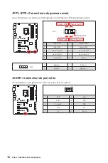
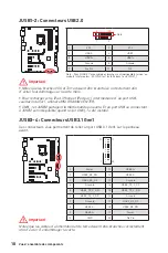
JUSB1~2 : Connecteurs USB 2.0

1

2

10

Note

9

1

VCC

2

VCC

3

USB0-

4

USB1-

5

USB0+

6

USB1+

7

Ground

8

Ground

9

No Pin

10

NC

Note : Pour JUSB2, l

ensemble des broches sont indisponible lorsqu

un 

module Intel wireless-AC (CNVi) est installé dans le slot CNVI_1.

 Important


y

Notez que les broches VCC et Terre doivent être branchées correctement afin 

d

éviter tout dommage sur la carte mère.


y

Pour recharger votre iPad, iPhone et iPod par l

intermédiaire d

un port USB, 

veuillez installer l

utilitaire MSI


DRAGON CENTER.


y

CNVI_1 et JUSB2 partagent la même bande passante. Et un port USB se connectant 

à JUSB2 est indispobible quand le slot CNVI_1 a été installé.

JUSB3~4 : Connecteurs USB 3.1 Gen1

Ces connecteurs vous permettent de relier un port USB 3.1 Gen1 sur le panneau 

avant.

1

10

11

20

1

Power

11

USB2.0+

2

USB3_RX_DN

12

USB2.0-

3

USB3_RX_DP

13

Ground

4

Ground

14

USB3_TX_C_DP

5

USB3_TX_C_DN

15

USB3_TX_C_DN

6

USB3_TX_C_DP

16

Ground

7

Ground

17

USB3_RX_DP

8

USB2.0-

18

USB3_RX_DN

9

USB2.0+

19

Power

10

GND

20

No Pin

 Important

Notez que les câbles d

alimentation et de terre doivent être branchés correctement 

afin d

éviter d

endommager la carte.  

Summary of Contents for MPG GAMING PLUS Z390

Page 1: ...ur Installation Ihres Computers Manche Installationen bieten auch die Videodemonstrationen Klicken Sie auf die URL um diese Videoanleitung mit Ihrem Browser auf Ihrem Handy oder Table anzusehen Oder s...

Page 2: ...II Quick Start Installing a Processor Installation des Prozessors Installer un processeur http youtu be bf5La099urI 1 2 3 6 4 5 7 8 9...

Page 3: ...III Quick Start http youtu be T03aDrJPyQs Installing DDR4 memory Installation des DDR4 Speichers Installer une m moire DDR4 DDR4 DIMMB2 DIMMB2 DIMMB1 DIMMA2 DIMMA2 DIMMA2 DIMMA1 1 1 2 2 3 3...

Page 4: ...u avant R E S E T S W P O W E R S W P O W E R L E D P O W E R L E D H D D L E D HDD LED RESET SW JFP1 HDD LED HDD LED HDD LED POWER LED POWER LED POWER LED 1 2 10 9 Power LED HDD LED Reset Switch Rese...

Page 5: ...V Quick Start Installing the Motherboard Installation des Motherboards Installer la carte m re BAT1 1 2...

Page 6: ...VI Quick Start http youtu be RZsMpqxythc Installing SATA Drives Installation der SATA Laufwerke Installer le disque dur SATA SATA 1 2 3 4 5...

Page 7: ...VII Quick Start 1 2 3 4 5 6 http youtu be mG0GZpr9w_A Installing a Graphics Card Einbau der Grafikkarte Installer une carte graphique...

Page 8: ...VIII Quick Start Connecting Peripheral Devices Peripherieger te Connecter un p riph rique anschliessen...

Page 9: ...IX Quick Start http youtu be gkDYyR_83I4 Connecting the Power Connectors Stromanschl sse anschliessen Connecter les c bles du module d alimentation ATX_PWR1 CPU_PWR1...

Page 10: ...X Quick Start 1 4 2 3 Power On Einschalten Mettre sous tension...

Page 11: ...ort Connector 16 CPU_PWR1 ATX_PWR1 Power Connectors 17 JUSB1 2 USB 2 0 Connectors 18 JUSB3 4 USB 3 1 Gen1 Connectors 18 CPU_FAN1 PUMP_FAN1 SYS_FAN1 5 Fan Connectors 19 JAUD1 Front Audio Connector 20 J...

Page 12: ...computer before installation is completed This could cause permanent damage to the components as well as injury to the user y If you need help during any installation step please consult a certified c...

Page 13: ...nsion Slot y 2x PCIe 3 0 x16 slots y 4x PCIe 3 0 x1 slots y 1 x M 2 slot with E key for Integrated Intel Wireless AC CNVi module only Onboard Graphics y 1x HDMI port supports a maximum resolution of 4...

Page 14: ...the back panel 4 ports available through the internal USB 3 1 connectors 6x USB 2 0 High speed USB ports 2 Type A ports on the back panel 4 ports available through the internal USB 2 0 connectors The...

Page 15: ...mp connector y 5x 4 pin system fan connectors y 1x Front panel audio connector y 2x System panel connectors y 1x Chassis Intrusion connector y 1x TPM module connector y 2x 4 pin RGB LED connectors y 1...

Page 16: ...TIMIZATION y OC Performance y Hardware Monitor y Eyerest y LAN Manager y Live Update Please refer to http download msi com manual mb DRAGONCENTER2 pdf for more details Special Features y Audio Audio B...

Page 17: ...GAMING MOUSE Control APP Player y BIOS Click BIOS 5 Package contents Please check the contents of your motherboard package It should contain Motherboard MPG Z390 GAMING PLUS Cable SATA 6Gb s Cables 2...

Page 18: ...Off No link Yellow Linked Blinking Data activity Speed LED Status Description Off 10 Mbps connection Green 100 Mbps connection Orange 1 Gbps connection LAN Port LED Status Table Audio Ports Configurat...

Page 19: ...he speakers that you plugged in front or rear panel by adjust the bar y Advanced Settings provides the mechanism to deal with 2 independent audio streams y Jack Status depicts all render and capture d...

Page 20: ...Rear I O Panel Audio jacks to headphone and microphone diagram Audio jacks to stereo speakers diagram Audio jacks to 7 1 channel speakers diagram AUDIO INPUT Rear Front Side Center Subwoofer AUDIO INP...

Page 21: ...1 CPU Socket PCI_E1 PCI_E2 JBAT1 PCI_E3 CNVI_1 PCI_E4 PCI_E5 PCI_E6 JAUD1 DIMMA2 DIMMB1 DIMMB2 JRGB2 CPU_FAN1 PUMP_FAN1 SYS_FAN1 SYS_FAN5 SYS_FAN4 SYS_FAN2 SYS_FAN3 ATX_PWR1 JUSB4 JUSB3 M2_1 M2_2 JFP2...

Page 22: ...before booting your system y Overheating can seriously damage the CPU and motherboard Always make sure the cooling fans work properly to protect the CPU from overheating Be sure to apply an even laye...

Page 23: ...or less for 32 bit Windows OS due to the memory address limitation Therefore we recommended that you to install 64 bit Windows OS if you want to install more than 4GB memory on the motherboard y Some...

Page 24: ...power supply and unplug the power supply power cable from the power outlet Read the expansion card s documentation to check for any necessary additional hardware or software changes SATA1 6 SATA 6Gb...

Page 25: ...tion for your M 2 SSD 3 Insert your M 2 SSD into the M 2 slot at a 30 degree angle 4 Secure the M 2 SSD in place with the supplied M 2 screw 4 Supplied M 2 screw Video Demonstration Watch the video to...

Page 26: ...ptional serial port with bracket JFP1 JFP2 Front Panel Connectors These connectors connect to the switches and LEDs on the front panel 1 2 10 9 Power LED HDD LED Reset Switch Reserved Power Switch JFP...

Page 27: ...es 9 5VSB 21 5V 10 12V 22 5V 11 12V 23 5V 12 3 3V 24 Ground 5 4 1 8 CPU_PWR1 1 Ground 5 12V 2 Ground 6 12V 3 Ground 7 12V 4 Ground 8 12V Important Make sure that all the power cables are securely conn...

Page 28: ...ease install MSI DRAGON CENTER utility y The CNVI_1 and JUSB2 share the same bandwidth And one USB port connecting to JUSB2 is unavailable when the CNVI_1 slot has been installed JUSB3 4 USB 3 1 Gen1...

Page 29: ...2V 3 Sense 4 Speed Control Signal DC Mode pin definition 1 Ground 2 Voltage Control 3 Sense 4 NC Pin definition of fan connectors CPU_FAN1 PUMP_FAN1 SYS_FAN1 5 Fan Connectors Fan connectors can be cla...

Page 30: ...Press F10 to save and exit and then press the Enter key to select Yes 6 Once the chassis cover is opened again a warning message will be displayed on screen when the computer is turned on Resetting t...

Page 31: ...the computer and unplug the power cord 2 Use a jumper cap to short JBAT1 for about 5 10 seconds 3 Remove the jumper cap from JBAT1 4 Plug the power cord and Power on the computer 1 2 14 13 1 LPC Clock...

Page 32: ...LED strip y Please use MSI s software to control the extended LED strip JRGB1 JRGB2 RGB LED connectors The JRGB1 JRGB2 connector allows you to connect the 5050 RGB LED strips 12V 1 JRGB1 2 JRGB1 JRGB...

Page 33: ...up notification then select Run DVDSetup exe to open the installer If you turn off the AutoPlay feature from the Windows Control Panel you can still manually execute the DVDSetup exe from the root pa...

Page 34: ...e following methods to enter BIOS setup y Press Delete key when the Press DEL key to enter Setup Menu F11 to enter Boot Menu message appears on the screen during the boot process y In MSI DRAGON CENTE...

Page 35: ...e refer the following methods to enter flash mode Reboot and press Ctrl F5 key during POST and click on Yes to reboot the system Reboot and press Del key during POST to enter BIOS Click the M FLASH bu...

Page 36: ...le if the X M P supported memory module is installed y Setup Mode switch press this tab or the F7 key to switch between Advanced mode and EZ mode y Screenshot click on this tab or the F12 key to take...

Page 37: ...the fan speed by percentage y Favorites menu press the F3 key to enter Favorites menu It allows you to create personal BIOS menu where you can save and access favorite frequently used BIOS setting it...

Page 38: ...he descriptions of EZ Mode Overview section y BIOS menu selection the following options are available SETTINGS allows you to specify the parameters for chipset and boot devices OC allows you to adjust...

Page 39: ...OC settings for OC expert to configure in BIOS setup Note We use as the symbol for the OC settings of Expert mode f CPU Ratio Auto Sets the CPU ratio that is used to determine CPU clock speed This it...

Page 40: ...his function fEnhanced Turbo Auto Enables or disables Enhanced Turbo function for all CPU cores to boost CPU performance This item appears when the installed CPU supports this function Auto This setti...

Page 41: ...wer Press Enter to enter the sub menu In the sub menu you can setup some protecting conditions about voltage current temputure for CPU f CPU Voltages control Auto These options allows you to set the v...

Page 42: ...ows you to select the number of active CPU cores fLimit CPUID Maximum Disabled Enables or disables the extended CPUID value Enabled BIOS limits the maximum CPUID input value to circumvent boot problem...

Page 43: ...ting will be configured automatically by BIOS Enabled Detects the idle state of system and reduce CPU power consumption accordingly Disabled Disable this function fC1E Support Disabled Enables or disa...

Page 44: ...Limit W fShort Duration Power Limit W Auto Sets the short duration TDP power limit for CPU in Turbo Boost mode fCPU Current Limit A Auto Sets maximum current limit of CPU package in Turbo Boost mode W...

Page 45: ...CPU_PWR1 ATX_PWR1 Stromanschl sse 17 JUSB1 2 USB 2 0 Anschl sse 18 JUSB3 4 USB 3 1 Gen1 Anschl sse 18 CPU_FAN1 PUMP_FAN1 SYS_FAN1 5 Stromanschl sse f r L fter 19 JAUD1 Audioanschluss des Frontpanels 2...

Page 46: ...ter nicht bevor die Installation abgeschlossen ist Dies k nnte permanente Sch den an den Komponenten sowie zu das Verletzung des Benutzers verursachen y Sollten Sie Hilfe bei der Installation ben tige...

Page 47: ...tze y 4x PCIe 3 0 x1 Steckpl tze y 1 x M 2 Steckplatz mit dem E Key nur f r das integrierte Intel Wireless AC CNVi Modul Onboard Grafik y 1x HDMI Anschluss Unterst tzung einer maximalen Aufl sung von...

Page 48: ...l sse stehen durch die internen USB 3 1 Anschluss zur Verf gung 6x USB 2 0 High speed USB Anschl sse 2 Typ A Anschl sse an der r ckseitigen Anschlussleiste 4 Anschl sse stehen durch die internen USB 2...

Page 49: ...f r die Wasserpumpe y 5x 4 polige System L fter Anschl sse y 1x Audioanschluss des Frontpanels y 2x Frontpanel Anschl sse y 1x Geh usekontaktschalter y 1x TPM Anschluss y 2x 4 polige RGB LED Anschl ss...

Page 50: ...Leistung y Hardware Monitor y Eyerest y LAN Manager y Live Update Weitere Informationen finden Sie unter http download msi com manual mb DRAGONCENTER2 pdf Besondere Funktionen y Audio Audio Boost y N...

Page 51: ...ng APP Player y BIOS Click BIOS 5 Packungsinhalt berpr fen Sie den Packungsinhalt des Mainboards Die Packung sollte enthalten Motherboard MPG Z390 GAMING PLUS Kabel SATA 6Gb s Kabel 2 Zubeh r M 2 Schr...

Page 52: ...ne In Line Out Vorderer Lautsprecher Hinterer Lautsprecher Mitte Subwoofer Ausgang Seitliche Lautsprecher Mic In Verbindet Blank Leer Verbindung Aktivit t LED Zustand Bezeichnung Aus Keine Verbindung...

Page 53: ...Front Panel oder auf der R ckseite des PCs eingesteckt sind y Erweiterte Einstellungen Erm glicht die zeitgleiche Verwendung von zwei Audiostreams y Verbindungsstatus Bildet die angeschlossenen Rende...

Page 54: ...ckseite E A Audiobuchsen f r den Anschluss von einem Kopfh rer und Mikrofon Audiobuchsen f r Stereo Lautsprecher Audiobuchsen f r 7 1 Kanal Anlage AUDIO INPUT Rear Front Side Center Subwoofer AUDIO I...

Page 55: ...WR1 CPU Sockel PCI_E1 PCI_E2 JBAT1 PCI_E3 CNVI_1 PCI_E4 PCI_E5 PCI_E6 JAUD1 DIMMA2 DIMMB1 DIMMB2 JRGB2 CPU_FAN1 PUMP_FAN1 SYS_FAN1 SYS_FAN5 SYS_FAN4 SYS_FAN2 SYS_FAN3 ATX_PWR1 JUSB4 JUSB3 M2_1 M2_2 JF...

Page 56: ...ng besch digt die CPU und das System nachhaltig Stellen Sie stets eine korrekte Funktionsweise des CPU K hlers sicher um die CPU vor berhitzung zu sch tzen Stellen Sie sicher dass eine gleichm ige Sch...

Page 57: ...ines 32 Bit Windows Betriebssystem bei 4GB oder weniger liegt Wenn Sie mehr als 4 GB Speicher auf dem Motherboard einbauen m chten empfehlen wir deshalb ein 64 Bit Windows Betriebssystem zu installier...

Page 58: ...aus der Steckdose herausziehen bevor Sie eine Erweiterungskarte installieren oder entfernen Lesen Sie bitte auch die Dokumentation der Erweiterungskarte um notwendige zus tzliche Hardware oder Softwa...

Page 59: ...ie eine M 2 SSD im 30 Grad Winkel in den M 2 Steckplatz 4 Schrauben Sie die M 2 SSD mit der mitgelieferten M 2 Schraube fest 4 Mitgelieferte M 2 Schraube Video Demonstration Eine anschauliche Darstell...

Page 60: ...lle Schnittstelle mit dem Einbausatze verbinden JFP1 JFP2 Frontpanel Anschl sse Diese Anschl sse verbinden die Schalter und LEDs des Frontpanels 1 2 10 9 Power LED HDD LED Reset Switch Reserved Power...

Page 61: ...21 5V 10 12V 22 5V 11 12V 23 5V 12 3 3V 24 Ground 5 4 1 8 CPU_PWR1 1 Ground 5 12V 2 Ground 6 12V 3 Ground 7 12V 4 Ground 8 12V Wichtig Stellen Sie sicher dass alle Anschl sse mit den richtigen Anschl...

Page 62: ...n Sie bitte die MSI DRAGON CENTER Software y CNVI_1 und JUSB2 teilen die selbe Bandbreite Der USB Anschluss der mit JUSB2 verbunden ist ist nicht verf gbar wenn der CNVI_1 Steckplatz installiert wurde...

Page 63: ...r L fter Diese Anschl sse k nnen im PWM Pulse Width Modulation Modus oder Spannungsmodus betrieben werden Im PWM Modus bieten die L fteranschl sse konstante 12 V Ausgang und regeln die L ftergeschwin...

Page 64: ...und dr cken Sie dann die Enter Taste um Ja auszuw hlen 6 Bei eingeschaltetem Computer wird eine Warnmeldung auf dem Bildschirm angezeigt wenn die Geh useabdeckung wieder ge ffnet wird Geh usekontakt W...

Page 65: ...erwenden Sie eine Steckbr cke um JBAT1 f r 5 10 Sekunden kurzzuschlie en 3 Entfernen Sie die Steckbr cke von JBAT1 4 Stecken Sie das Kabel Ihres Computers in die Steckdose hinein und schalten Sie den...

Page 66: ...ein und ausbauen y Bitte verwenden Sie die MSI Software zur Steuerung des LED Leuchtstreifens JRGB1 JRGB2 RGB LED Anschl sse Mit dem JRGB1 JRGB2 Anschluss k nnen Sie den 5050 RGB LED Streifen 12 V ans...

Page 67: ...aus und w hlen Sie DVDSetup exe starten aus um den Installer zu ffnen Wenn Sie die AutoPlay Funktionen in der Windows Systemsteuerung ausschalten k nnen Sie das Programm DVDSetup exe im Hauptverzeichn...

Page 68: ...S Setup aufzurufen y W hrend des BOOT Vorgangs dr cken Sie die Taste ENTF wenn die Meldung Press DEL key to enter Setup Menu F11 to enter Boot Menu erscheint y Verwenden Sie die MSI DRAGON CENTER Anwe...

Page 69: ...des POST Vorgangs die Taste Ctrl F5 und klicken Sie auf Yes Ja tum das System neu zu starten Beim Neustart dr cken Sie w hrend des POST Vorgangs die Taste Del Entf w hrend des POST Vorgangs die Taste...

Page 70: ...ieser Registerkarte oder der F7 Taste k nnen Sie zwischen dem Erweiterten Modus und EZ Modus wechseln y Screenshot W hlen Sie diese Registerkarte oder bet tigen Sie die F12 Taste um einen Screenshot z...

Page 71: ...nliches BIOS Men erstellen in dem Sie die h ufig verwendeten oder favorisierten BIOS Einstellungsoptionen ausw hlen k nnen Default HomePage ber diese Option k nnen Sie ein BIOS Men zum Beispiel Einst...

Page 72: ...us Abschritt y BIOS Men Auswahl Die folgenden Optionen stehen zur Verf gung SETTINGS Mit diesem Men k nnen Sie die Parameter f r Chipsatz Boot Ger te angeben OC Hier k nnen Sie die Frequenz und Spannu...

Page 73: ...lungen anzuzeigen Normal Bietet normale bertaktungseinstellungen im BIOS Setup Expert Bietet die erweiterten bertaktungseinstellungen f r den erfahrenen Benutzer welche die Einstellungen im BIOS Setup...

Page 74: ...rn Disabled Deaktiviert EIST fIntel Turbo Boost Enabled Aktivieren oder deaktivieren Sie Intel Turbo Boost Diese Option wird angezeigt wenn die installierte CPU diese Einstellungen unterst tzt Enabled...

Page 75: ...t l schen Sie bitte die CMOS Daten und stellen Sie die Standardeinstellungen wieder her Lesen Sie bitte den Abschnitt Steckbr cke zur CMOS L schung Clear CMOS Taste um die CMOS Daten zu l schen und di...

Page 76: ...F5 dr cken fDIMMA1 A2 B1 B2 Memory SPD Dr cken Sie die Eingabetaste Enter um das Untermen aufzurufen Das Untermen zeigt die Informationen des verwendeten Speichers an Nur Anzeige f CPU Features Dr ck...

Page 77: ...Applikationen Disabled Aktiviert nur die angeforderten Cache Zeilen fCPU AES Instructions Enabled Aktiviert oder deaktiviert die CPU AES Advanced Encryption Standard New Instructions Unterst tzung Die...

Page 78: ...eren Sie diese Funktion um die CPU Leistung automatisch zu erh hen wenn das System mehr Leistung ben tigt Disabled Deaktivieren Sie diese Funktion fLong Duration Power Limit W Auto Hier stellen Sie di...

Page 79: ...ATX_PWR1 Connecteurs d alimentation 17 JUSB1 2 Connecteurs USB 2 0 18 JUSB3 4 Connecteurs USB 3 1 Gen1 18 CPU_FAN1 PUMP_FAN1 SYS_FAN1 5 Connecteurs pour ventilateurs 19 JAUD1 Connecteur audio avant 2...

Page 80: ...ien fix s sur la carte m re ou ailleurs dans le bo tier de l ordinateur y Ne d marrez pas l ordinateur avant d avoir termin l installation Ceci peut endommager les composants ou vous blesser y Si vous...

Page 81: ...slots PCIe 3 0 x1 y 1 x slot M 2 avec E key pour le module Integrated Intel Wireless AC CNVi uniquement Sorties vid o int gr es y 1 x port HDMI supportant une r solution maximum de 4096x2160 24Hz y 1...

Page 82: ...A sur le panneau arri re 4 ports disponibles par l interm diaire des connecteurs USB 3 1 internes 6 x ports USB 2 0 High speed USB 2 ports Type A sur le panneau arri re 4 ports disponibles par l inter...

Page 83: ...y 5 x connecteurs de ventilateurs syst me 4 broches y 1 x connecteur audio avant y 2 x connecteurs de panneau syst me y 1 x connecteur intrusion ch ssis y 1 x connecteur de module TPM y 2 x connecteu...

Page 84: ...ON y OC Performance y Hardware Monitor y Eyerest y LAN Manager y Live Update R f rez vous au site http download msi com manual mb DRAGONCENTER2 pdf pour plus de d tails Fonctions sp ciales y Audio Aud...

Page 85: ...Joueur de APP y BIOS Click BIOS 5 Contenu V rifiez tous les articles dans le carton d emballage de votre carte m re L emballage doit contenir Carte m re MPG Z390 GAMING PLUS C ble C ble SATA 6Gb s 2 A...

Page 86: ...la connexion et l activit Etat Description Eteint Pas de connexion Jaune Connexion correcte Clignote Activit en cours LED indiquant la vitesse Etat Description Eteint D bit de 10 Mbps Vert D bit de 1...

Page 87: ...le panneau avant ou derri re en ajustant la barre de volume y Param tres avanc s fournit le m canisme pour g rer deux flux audio ind pendants y Etat des prises Jack pr sente tous les p riph riques de...

Page 88: ...isation des ports audio d di s au casque et au microphone Ilustration de l utilisation du port audio d di aux haut parleurs Ilustration de l utilisation des ports audio d di s aux haut parleurs 7 1 AU...

Page 89: ..._PWR1 Socket processeur PCI_E1 PCI_E2 JBAT1 PCI_E3 CNVI_1 PCI_E4 PCI_E5 PCI_E6 JAUD1 DIMMA2 DIMMB1 DIMMB2 JRGB2 CPU_FAN1 PUMP_FAN1 SYS_FAN1 SYS_FAN5 SYS_FAN4 SYS_FAN2 SYS_FAN3 ATX_PWR1 JUSB4 JUSB3 M2_...

Page 90: ...le processeur avant de d marrer votre syst me y La surchauffe peut facilement endommager le processeur et la carte m re Assurez vous toujours que le syst me de refroidissement fonctionne correctement...

Page 91: ...e la limitation de m moire Par cons quent il est recommand d installer le syst me d exploitation Windows 64 bit si vous voulez installer une m moire de plus de 4 Go sur la carte m re y Certaines m moi...

Page 92: ...tension et d brancher le cordon d alimentation avant d installer les cartes d extension R f rez vous la documentation des cartes pour v rifier si un composant ou un logiciel doit tre modifi SATA1 6 Co...

Page 93: ...ement appropri pour votre SSD M 2 3 Ins rez votre SSD M 2 dans le slot M 2 un angle de 30 degr s 4 Fixez le SSD M 2 avec la vis M 2 fournie 4 Vis M 2 fournie Vid o de d monstration R f rez vous la vid...

Page 94: ...n port s rie en option JFP1 JFP2 Connecteurs de panneau avant Ces connecteurs se lient aux interrupteurs et indicateurs LED du panneau avant 1 2 10 9 Power LED HDD LED Reset Switch Reserved Power Swit...

Page 95: ...1 5V 10 12V 22 5V 11 12V 23 5V 12 3 3V 24 Ground 5 4 1 8 CPU_PWR1 1 Ground 5 12V 2 Ground 6 12V 3 Ground 7 12V 4 Ground 8 12V Important Veuillez vous assurer que tous les c bles d alimentation sont br...

Page 96: ...rt USB veuillez installer l utilitaire MSIDRAGON CENTER y CNVI_1 et JUSB2 partagent la m me bande passante Et un port USB se connectant JUSB2 est indispobible quand le slot CNVI_1 a t install JUSB3 4...

Page 97: ...ol Signal D finition des broches en mode DC 1 Ground 2 Voltage Control 3 Sense 4 NC D finition des broches des connecteurs de ventilateur CPU_FAN1 PUMP_FAN1 SYS_FAN1 5 Connecteurs pour ventilateurs Le...

Page 98: ...F10 pour sauvegarder et quitter Ensuite appuyez sur la touche Enter Entr e pour choisir Yes Oui 6 D sormais si le bo tier du PC est ouvert quand l ordinateur est allum vous recevrez un message d alert...

Page 99: ...gnez l ordinateur et d branchez le c ble d alimentation de la prise lectrique 2 Utilisez un couvercle de cavalier pour fermer JBAT1 pour environ 5 10 secondes 3 Enlevez le couvercle de cavalier du JBA...

Page 100: ...r contr ler le ruban d extension LED JRGB1 JRGB2 Connecteurs LED RGB Le connecteur JRGB1 JRGB2 vous permet de connecter un ruban LED RGB de type 5050 12V 1 JRGB1 2 JRGB1 JRGB2 C ble d extension Ruban...

Page 101: ...DSetup exe pour ouvrir l outil d installation Si vous d sactivez la fonction AutoPlay dans le panneau de configuration Windows vous pouvez quand m me ex cuter manuellement DVDSetup exe partir du chemi...

Page 102: ...s y Pendant le d marrage lorsqu appara t le message Press DEL key to enter Setup Menu F11 to enter Boot Menu sur l cran veuillez appuyer sur la touche Suppr y Quand l ordinateur est d j en marche vous...

Page 103: ...f rer aux m thodes suivantes pour passer en mode flash Red marrez et appuyez sur la touche Ctrl F5 pendant le processus de POST et cliquez sur Yes Oui pour red marrer le syst me Red marrez et appuyez...

Page 104: ...ur la touche F12 pour prendre une capture d cran et la conserver dans le lecteur flash USB lecteur flash USB au format FAT ou FAT32 uniquement y Recherche cliquez sur cet onglet ou sur les touches Ctr...

Page 105: ...permet de contr ler manuellement la vitesse des ventilateurs y Le menu Favoris appuyez sur la touche F3 pour entrer dans le menu Favoris Il vous permet de cr er un menu BIOS personnalis o vous pourre...

Page 106: ...e p riph rique d marrage veuillez vous r f rer la partie EZ mode pour plus de pr cision y S lection du menu BIOS les options suivantes sont disponibles SETTINGS R glages permet de personnaliser les pa...

Page 107: ...et configurer dans les r glages BIOS Remarque Nous utilisons le symbole pour indiquer les r glages OC du mode Expert f CPU Ratio Auto D finit le ratio servant d terminer la vitesse d horloge du proce...

Page 108: ...v Disabled D sactive cette fonction fEnhanced Turbo Auto Active ou d sactive la fonction Enhanced Turbo pour tous les coeurs du processeur a n d augmenter les performances du processeur Ce menu appara...

Page 109: ...arrage de fa on acc l rer le d marrage du syst me Disabled La m moire est initialis e et test e chaque d marrage f DigitALL Power Appuyez sur la touche Entr e pour entrer dans le sous menu Dans le sou...

Page 110: ...Threading Disabled D sactive la fonction si le syst me n y est pas compatible fActive Processor Cores Control All Vous permet de choisir le nombre des coeurs actifs fLimit CPUID Maximum Disabled Acti...

Page 111: ...Enabled D tecte quand le syst me est inactif et r duit en cons quence la consommation d nergie du processeur Disabled D sactive cette fonction fC1E Support Disabled Active ou d sactive la fonction C1E...

Page 112: ...ion maximum que le TDP enveloppe thermique du processeur peut supporter sur une courte p riode et en mode Turbo Boost fCPU Current Limit A Auto D nit le niveau d alimentation maximum du package du pro...

Page 113: ...14 M2_1 2 M 2 M 15 JFP1 JFP2 16 JCOM1 16 CPU_PWR1 ATX_PWR1 17 JUSB1 2 USB 2 0 18 JUSB3 4 USB 3 1 Gen1 18 CPU_FAN1 PUMP_FAN1 SYS_FAN1 5 19 JAUD1 20 JCI1 20 JTPM1 TPM 21 JBAT1 CMOS BIOS 21 JRGB1 JRGB2...

Page 114: ...2 y y y y y y y y y y y y y y y y 60 C 140 F...

Page 115: ...200 OC 3000 OC 2800 OC 2666 2400 2133 y y non ECC y Intel Extreme Memory Profile XMP www msi com y 2x PCIe 3 0 x16 y 4x PCIe 3 0 x1 y 1 x M 2 E Intel Wireless AC CNVi y 1x HDMI 4096x2160 24 y 1x DVI D...

Page 116: ...peed USB 10 1 Type A 1 Type C 6x USB 3 1 Gen1 SuperSpeed USB 2 Type A 4 USB 3 1 6x USB 2 0 High speed USB 2 Type A 4 USB 2 0 CNVI_1 JUSB2 18 y Realtek ALC892 Codec 7 1 High Definition Audio y 1x PS 2...

Page 117: ...2 M 1 E y 2x USB 3 1 Gen1 4 USB 3 1 Gen1 y 2x USB 2 0 4 USB 2 0 y 1x 4 y 1x 4 Water Pump y 5x 4 y 1x y 2x y 1x y 1x TPM y 2x 4 y 1x y 1x CMOS NUVOTON NCT6797 y y y y ATX y 12 x 9 6 30 5 x 24 4 BIOS y...

Page 118: ...ion Dragon Center y GAME OPTIMIZATION y OC Performance y Hardware Monitor y Eyerest y LAN Manager y Live Update http download msi com manual mb DRAGONCENTER2 pdf y Audio Boost y GAMING LAN GAMING LAN...

Page 119: ...ire Technology DDR4 Boost Core Boost GAME Boost USB Type A C Intel Turbo USB 3 1 Gen2 y VR VR Ready y GAMING HOTKEY GAMING MOUSE Control APP Player y BIOS Click BIOS 5 MPG Z390 GAMING PLUS SATA 6 2 M...

Page 120: ...8 PS 2 LAN DVI D USB 3 1 Gen1 USB 2 0 USB 3 1 Gen2 USB 3 1 Gen2 Type C 10 100 1 LAN 2 4 6 8...

Page 121: ...9 Realtek Audio Console Realtek Audio Console y y y y y y...

Page 122: ...10 7 1 AUDIO INPUT Rear Front Side Center Subwoofer AUDIO INPUT...

Page 123: ...BAT1 PCI_E3 CNVI_1 PCI_E4 PCI_E5 PCI_E6 JAUD1 DIMMA2 DIMMB1 DIMMB2 JRGB2 CPU_FAN1 PUMP_FAN1 SYS_FAN1 SYS_FAN5 SYS_FAN4 SYS_FAN2 SYS_FAN3 ATX_PWR1 JUSB4 JUSB3 M2_1 M2_2 JFP2 JCI1 SATA 1 2 SATA 3 4 SATA...

Page 124: ...12 LGA 1151 LGA 1151 1 y y MSI y y y y y y MSI 50 7 DIMM...

Page 125: ...13 DIMM DIMMA1 DIMMB1 A B DIMMA2 DIMMB2 DIMMB2 DIMMB2 DIMMB1 DIMMA2 DIMMA2 DIMMA2 DIMMA1 y DIMMA2 y y DIMM 1 35 y 32 Windows 4 4 64 Windows y SPD Serial Presence Detect BIOS Memory Try It y y...

Page 126: ...CIe 3 0 x1 PCH PCI_E5 PCIe 3 0 x1 PCH PCI_E4 PCIe 3 0 x4 PCH PCI_E6 PCIe 3 0 x1 PCH y MSI Gaming Series Graphics Card Bolster y PCIe x16 PCI_E1 y SATA1 6 SATA 6 SATA 6 SATA y SATA y SATA y SATA2 M 2 S...

Page 127: ...ROM y Intel Optane M 2 1 2 3 30 1 M 2 2 M 2 M 2 SSD 3 M 2 SSD 2 30 4 M 2 SSD M 2 4 M 2 M 2 http youtu be JCTFABytrYA M 2 SATA SATA M 2 M2_1 PCIe SATA M2_2 PCIe SATA PCIe SATA PCIe SATA SATA1 SATA2 SAT...

Page 128: ...RI 10 No Pin JCOM1 JFP1 JFP2 1 2 10 9 Power LED HDD LED Reset Switch Reserved Power Switch JFP1 1 HDD LED 2 Power LED 3 HDD LED 4 Power LED 5 Reset Switch 6 Power Switch 7 Reset Switch 8 Power Switch...

Page 129: ...round 15 Ground 4 5V 16 PS ON 5 Ground 17 Ground 6 5V 18 Ground 7 Ground 19 Ground 8 PWR OK 20 Res 9 5VSB 21 5V 10 12V 22 5V 11 12V 23 5V 12 3 3V 24 Ground 5 4 1 8 CPU_PWR1 1 Ground 5 12V 2 Ground 6 1...

Page 130: ...y iPad iPhone iPod USB MSI DRAGON CENTER y CNVI_1 JUSB2 USB JUSB2 CNVI_1 JUSB3 4 USB 3 1 Gen1 USB 3 1 Gen1 1 10 11 20 1 Power 11 USB2 0 2 USB3_RX_DN 12 USB2 0 3 USB3_RX_DP 13 Ground 4 Ground 14 USB3_T...

Page 131: ...PWM DC PWM DC PWM 1 Ground 2 12V 3 Sense 4 Speed Control Signal DC 1 Ground 2 Voltage Control 3 Sense 4 NC CPU_FAN1 PUMP_FAN1 SYS_FAN1 5 PWM PulseWidth Modulation PWM 12 PWM DC CPU_FAN1 PUMP_FAN1 PWM...

Page 132: ...assis Intrusion Enabled 5 F10 Enter Yes 6 1 BIOS SETTINGS Security Chassis Intrusion Configuration 2 Chassis Intrusion Reset 3 F10 Enter Yes JAUD1 1 2 10 9 1 MIC L 2 Ground 3 MIC R 4 NC 5 Head Phone R...

Page 133: ...1 2 14 13 1 LPC Clock 2 3V Standby power 3 LPC Reset 4 3 3V Power 5 LPC address data pin0 6 Serial IRQ 7 LPC address data pin1 8 5V Power 9 LPC address data pin2 10 No Pin 11 LPC address data pin3 12...

Page 134: ...22 y JRGB1 JRGB2 5050 RGB 12 G R B 3 12 y 2 y RGB y MSI JRGB1 JRGB2 RGB LED JRGB1 JRGB2 5050 RGB 12 1 JRGB1 2 JRGB1 JRGB2 5050 RGB 12 1 JRGB1 1 JRGB2 1 12V 2 G 3 R 4 B EZ CPU DRAM DRAM VGA BOOT...

Page 135: ...Power On Self Test 5 USB 6 Press any key to boot from CD or DVD 7 Windows 10 1 Windows 10 2 MSI Driver Disc 3 Select to choose what happens with this disc Run DVDSetup exe Windows DVDSetup exe MSI Dr...

Page 136: ...OS y BIOS BIOS BIOS HELP y BIOS BIOS y Delete Press DEL key to enter Setup Menu F11 to enter Boot Menu y MSI DRAGON CENTER GO2BIOS BIOS F1 F2 F3 F4 F5 Memory Z F6 F7 EZ F8 F9 F10 F12 USB FAT FAT32 Ctr...

Page 137: ...S BIOS CMOS BIOS BIOS M FLASH BIOS MSI BIOS USB BIOS 1 USB 2 Ctrl F5 POST Yes Del POST BIOS M FLASH Yes 3 BIOS BIOS 4 BIOS MSI DRAGON CENTER BIOS 1 MSI DRAGON CENTER 2 BIOS Update 3 Scan 4 Download BI...

Page 138: ...26 BIOS EZ EZ BIOS F7 XMP M Flash GAME BOOST y GAME BOOST GAME BOOST y XMP X M P Extreme Memory Profile X M P X M P y F7 EZ y F12 USB FAT FAT32 y Ctrl F BIOS F6 F10 F12 y BIOS y BIOS...

Page 139: ...lp y LAN Option ROM M 2 Optane Genie HD audio controller AHCI RAID CPU Fan Fail Warning Control BIOS Log Review y M Flash M Flash BIOS USB y y F3 BIOS BIOS BIOS OC BIOS 1 5 BIOS BIOS 1 5 1 BIOS OC OC...

Page 140: ...28 BIOS F7 EZ BIOS GAME BOOST XMP BIOS BIOS y GAME BOOST XMP EZ y BIOS SETTINGS OC M FLASH BIOS USB OC PROFILE HARDWARE MONITOR BOARD EXPLORER y BIOS...

Page 141: ...y GAME BOOST f OC Explore Mode Normal Normal BIOS Expert BIOS Expert f CPU Ratio Auto CPU Ratio Apply Mode All Core f Adjusted CPU Frequency f CPU Ratio Offset When Running AVX Auto AVX Auto BIOS f R...

Page 142: ...fEIST Enabled Enhanced Intel SpeedStep Enabled EIST Disabled EIST fIntel Turbo Boost Enabled Intel Turbo Boost Enabled Disabled fEnhanced Turbo Auto Enhanced Turbo Auto BIOS Enabled Disabled f CPU Bas...

Page 143: ...y It Disabled f Advanced DRAM Con guration Enter CMOS CMOS CMOS BIOS f Memory Fast Boot Auto Auto BIOS Enabled Disabled f DigitALL Power Enter f CPU Voltages control Auto Auto BIOS f DRAM Voltages con...

Page 144: ...nter f CPU Features Enter fHyper Threading Enabled Intel Hyper Threading Enable Intel Hyper Threading Disabled fActive Processor Cores Control All fLimit CPUID Maximum Disabled CPUID Enabled BIOS CPUI...

Page 145: ...Enabled MLC Spatial prefetcher Enabled Disabled fCPU AES Instructions Enabled CPU AES Advanced Encryption Standard New Instructions fIntel Adaptive Thermal Monitor Enabled Enabled Disabled fIntel C S...

Page 146: ...Boost Normal Enabled Disabled fLong Duration Power Limit W Auto TDP Turbo Boost fLong Duration Maintained s Auto Long Duration Power Limit fShort Duration Power Limit W Auto TDP Turbo Boost fCPU Curr...

Page 147: ...d using applicable European Harmonized Standards The point of contact for regulatory matters is MSI MSI NL Eindhoven 5706 5692 ER Son B B B VCCI B C Tick Compliance Battery Information European Union...

Page 148: ...wil MSI u eraan herinneren dat De richtlijn van de Europese Unie EU met betrekking tot Vervuiling van Electrische en Electronische producten 2002 96 EC die op 13 Augustus 2005 in zal gaan kunnen niet...

Page 149: ...ti ricorda che In base alla Direttiva dell Unione Europea EU sullo Smaltimento dei Materiali Elettrici ed Elettronici Direttiva 2002 96 EC in vigore dal 13 Agosto 2005 prodotti appartenenti alla categ...

Page 150: ...ior notice Technical Support If a problem arises with your system and no solution can be obtained from the user guide please contact your place of purchase or local distributor Alternatively please tr...

Reviews: