background image

14

Contenu 

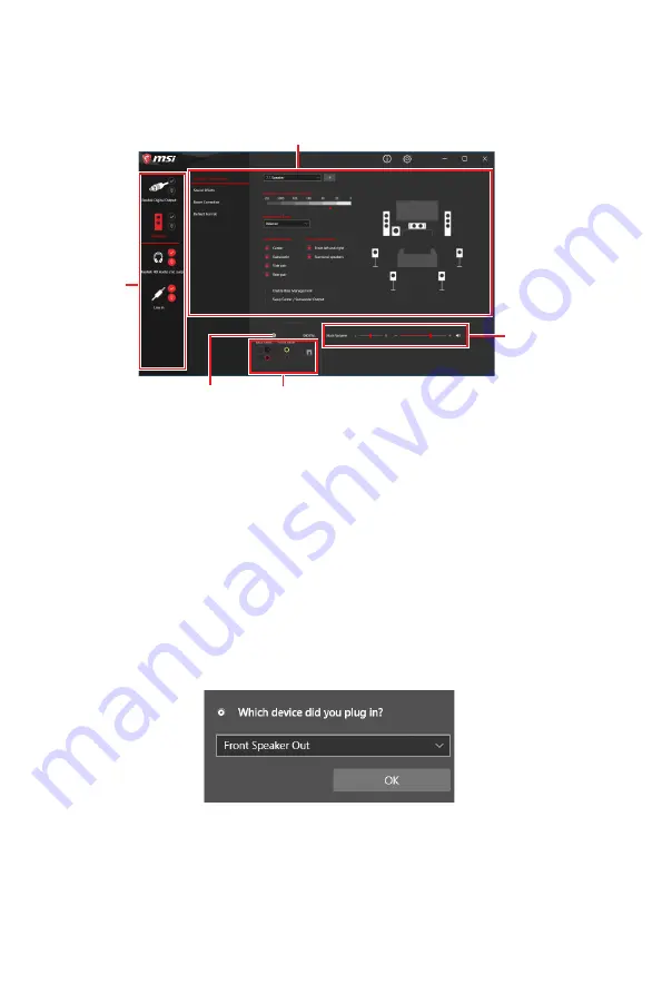
Realtek Audio Console

Après l’installation de Realtek Audio Console,  vous pouvez l’utiliser pour modifier les 

paramètres du son afin d’obtenir une meilleure expérience sonore.


Sélection du périphérique

 - vous permet de sélectionner une source de sortie 

audio pour en modifier les paramètres. Le symbole de coche indique le périphérique 

sélectionné par défaut.


Amélioration d’application

 - les diverses options vous fournissent un guide complet 

des effets acoustiques proposés pour les périphériques de sortie et d’entrée.


Volume principal

 - contrôle le volume ou équilibre le son gauche/droite des haut 

parleurs branchés sur le panneau avant ou derrière en ajustant la barre de volume.


État des prises Jack

 - présente tous les périphériques de diffusion et de capture 

connectés à votre ordinateur. 


Paramètres du connecteur

 - configure les paramètres de connexion.

Auto popup dialog

Lorsqu’un périphérique est branché sur une prise audio, une fenêtre de dialogue 

apparaît et vous demande de choisir le périphérique connecté que vous souhaitez 

utiliser.

Chaque jack est réglé avec ses paramètres par défaut comme indiqué sur la page 

suivante.


Important

Les photos ci-dessus ne sont données qu’à titre de référence et peuvent varier selon 

le produit que vous avez acheté. 

État des prises Jack

Paramètres du connecteur  

Sélection du 

périphérique

Volume principal

Amélioration d’application

Summary of Contents for MPG Z590M

Page 1: ...ur Installation Ihres Computers Manche Installationen bieten auch die Videodemonstrationen Klicken Sie auf die URL um diese Videoanleitung mit Ihrem Browser auf Ihrem Handy oder Table anzusehen Oder s...

Page 2: ...II Quick Start 1 2 3 6 4 5 7 8 9 https youtu be Xv89nhFk1vc Installing a Processor Installation des Prozessors Installer un processeur...

Page 3: ...III Quick Start DIMMA2 DIMMA2 DIMMB2 DIMMA1 DIMMA2 DIMMB1 DIMMB2 http youtu be T03aDrJPyQs Installing DDR4 memory Installation des DDR4 Speichers Installer une m moire DDR4 DDR4...

Page 4: ...witch JFP1 1 HDD LED 2 Power LED 3 HDD LED 4 Power LED 5 Reset Switch 6 Power Switch 7 Reset Switch 8 Power Switch 9 Reserved 10 No Pin R E S E T S W P O W E R S W P O W E R L E D P O W E R L E D H D...

Page 5: ...V Quick Start https youtu be wWI6Qt51Wnc Installing the Motherboard Installation des Motherboards Installer la carte m re Youtube 1 Torque 3 kgf cm 3 kgf cm 0 3 N m 2 6 lbf in 2...

Page 6: ...VI Quick Start http youtu be gkDYyR_83I4 CPU_PWR1 ATX_PWR1 CPU_PWR2 Connecting the Power Connectors Stromanschl sse anschliessen Connecter les c bles du module d alimentation...

Page 7: ...VII Quick Start http youtu be RZsMpqxythc 1 2 3 4 5 Installing SATA Drives Installation der SATA Laufwerke Installer le disque dur SATA SATA...

Page 8: ...VIII Quick Start http youtu be mG0GZpr9w_A 1 2 3 4 5 6 Installing a Graphics Card Einbau der Grafikkarte Installer une carte graphique...

Page 9: ...IX Quick Start Connecting Peripheral Devices Peripherieger te Connecter un p riph rique anschliessen...

Page 10: ...X Quick Start 4 3 1 2 Power On Einschalten Mettre sous tension...

Page 11: ...Connector 22 JFP1 JFP2 Front Panel Connectors 23 JDASH1 Tuning Controller connector 23 CPU_PWR1 2 ATX_PWR1 Power Connectors 24 JUSB4 USB 3 2 Gen 2 Type C Connector 25 JUSB3 USB 3 2 Gen 1 Connector 25...

Page 12: ...e computer before installation is completed This could cause permanent damage to the components as well as injury to the user If you need help during any installation step please consult a certified c...

Page 13: ...nd off required for a motherboard on the mounting plate in the case To prevent damage to the motherboard any unnecessary mounting stand off between the motherboard circuits and the computer case is pr...

Page 14: ...locking frequency 1DPC 1R Max speed up to 5333 MHz 1DPC 2R Max speed up to 4700 MHz 2DPC 1R Max speed up to 4400 MHz 2DPC 2R Max speed up to 4000 MHz Supports Dual Channel mode Supports non ECC mode u...

Page 15: ...Supports up to PCIe 4 0 x4 Supports 2242 2260 2280 storage devices M2_2 slot from Z590 chipset Supports up to PCIe 3 0 x4 Supports up to SATA 6Gb s Supports 2242 2260 2280 storage devices Intel Optane...

Page 16: ...Hub GL850G 4x USB 2 0 ports are available through the internal connectors Audio Realtek ALC4080 7 1 Channel High Definition Audio Supports S PDIF output LAN 1x Intel I225 V 2 5G LAN controller Wireles...

Page 17: ...itional 2 USB 3 2 Gen 1 5Gbps ports 2x USB 2 0 connectors supports additional 4 USB 2 0 ports 1x 4 pin CPU fan connector 1x 4 pin water pump fan connector 2x 4 pin system fan connectors 1x Front panel...

Page 18: ...roller NUVOTON NCT6687 R Controller Chip Hardware Monitor CPU System Chipset temperature detection CPU System Pump fan speed detection CPU System Pump fan speed control Form Factor Micro ATX Form Fact...

Page 19: ...ights LAN Manager Mystic Light Ambient Link Frozr AI Cooling User Scenario True Color Live Update Monitor Super Charger Speed Up Special Features Audio Audio Boost 5 Sound Tune Network 2 5G LAN LAN Ma...

Page 20: ...rmance Lightning Gen 4 PCI E Slot Lightning Gen 4 M 2 Multi GPU CrossFire Technology DDR4 Boost Core Boost GAME Boost Lightning USB 20G USB 3 2 Gen 2 10G USB with Type A C Front USB Type C Dual CPU Po...

Page 21: ...s 1 Application USB drive with drivers utilities 1 Accessories Wi Fi Antenna 1 M 2 screws 2 pcs pack 1 Dragon Badge 1 MPG sticker 1 SATA cable stickers 1 Product registration card 1 Documentation User...

Page 22: ...link Yellow Linked Blinking Data activity Speed LED Status Description Off 10 Mbps connection Green 100 1000 Mbps connection Orange 2 5 Gbps connection Rear I O Panel USB 3 2 Gen 2 10Gbps Type A 2 5...

Page 23: ...trols the volume or balance the right left side of the speakers that you plugged in front or rear panel by adjust the bar Jack Status depicts all render and capture devices currently connected with yo...

Page 24: ...ackage contents Audio jacks to headphone and microphone diagram Audio jacks to stereo speakers diagram Audio jacks to 7 1 channel speakers diagram AUDIO INPUT AUDIO INPUT Rear Front Side Center Subwoo...

Page 25: ...15 Package contents Installing Antennas 1 Screw the antennas tight to the antenna connectors as shown below 2 Orient the antennas 1 2...

Page 26: ...SYS_FAN2 JBAT1 JTBT1 JTPM1 JRGB1 SATA 1 2 SATA 3 4 SATA 5 6 JDASH1 M2_2 SYS_FAN1 JUSB4 M2_1 JCI1 JUSB1 CPU_FAN1 PUMP_FAN1 PCI_E1 PCI_E2 PCI_E3 Processor Socket CPU_PWR1 CPU_PWR2 JRAINBOW2 JAUD1 JFP2...

Page 27: ...mal tape between the CPU and the heatsink to enhance heat dissipation Whenever the CPU is not installed always protect the CPU socket pins by covering the socket with the plastic cap If you purchased...

Page 28: ...hen overclocking due to the memory frequency operates dependent on its Serial Presence Detect SPD Go to BIOS and find the DRAM Frequency to set the memory frequency if you want to operate the memory a...

Page 29: ...I_E1 slot is recommended When adding or removing expansion cards always turn off the power supply and unplug the power supply power cable from the power outlet Read the expansion card s documentation...

Page 30: ...Remove the M 2 SHIELD FROZR and remove the protective films from the thermal pads of heatsink 2 2 1 1 1 1 M2_1 M2_2 Important Intel RST only supports PCIe M 2 SSD with UEFI ROM Intel Optane Memory Rea...

Page 31: ...f you install 2280 M 2 into M2_1 slot 3 Secure the supplied M 2 standoff according to your M 2 SSD length if need 4 Insert your M 2 SSD into the M 2 slot at a 30 degree angle 5 Secure the M 2 SSD in p...

Page 32: ...smission otherwise SATA cables have identical plugs on either sides of the cable However it is recommended that the flat connector be connected to the motherboard for space saving purposes SATA2 will...

Page 33: ...ower Switch JFP1 1 HDD LED 2 Power LED 3 HDD LED 4 Power LED 5 Reset Switch 6 Power Switch 7 Reset Switch 8 Power Switch 9 Reserved 10 No Pin 1 JFP2 Speaker Buzzer 1 Speaker 2 Buzzer 3 Buzzer 4 Speake...

Page 34: ...2 5V 11 12V 23 5V 12 3 3V 24 Ground 5 4 1 8 CPU_PWR1 1 Ground 5 12V 2 Ground 6 12V 3 Ground 7 12V 4 Ground 8 12V Important Make sure that all the power cables are securely connected to a proper ATX po...

Page 35: ...2 Gen 1 Connector This connector allows you to connect USB 3 2 Gen 1 5Gbps ports on the front panel Important Note that the Power and Ground pins must be connected correctly to avoid possible damage 1...

Page 36: ...to avoid possible damage In order to recharge your iPad iPhone and iPod through USB ports please install MSI Center utility 1 2 12 11 1 SPI Power 2 SPI Chip Select 3 Master In Slave Out SPI Data 4 Mas...

Page 37: ...n speed You can switch between PWM mode and DC mode and adjust fan speed in BIOS HARDWARE MONITOR Select PWM mode or DC mode Important Make sure fans are working properly after switching the PWM DC mo...

Page 38: ...chassis cover 3 Go to BIOS SETTINGS Security Chassis Intrusion Configuration 4 Set Chassis Intrusion to Enabled 5 Press F10 to save and exit and then press the Enter key to select Yes 6 Once the chass...

Page 39: ...off the computer and unplug the power cord 2 Use a jumper cap to short JBAT1 for about 5 10 seconds 3 Remove the jumper cap from JBAT1 4 Plug the power cord and Power on the computer EZ Debug LED The...

Page 40: ...d from the power outlet before installing or removing the RGB LED strip Please use MSI s software to control the extended LED strip JRGB1 RGB LED connector The JRGB connector allows you to connect the...

Page 41: ...tor supports up to 200 LEDs Always turn off the power supply and unplug the power cord from the power outlet before installing or removing the RGB LED strip Please use MSI s software to control the ex...

Page 42: ...If you turn off the AutoPlay feature from the Windows Control Panel you can still manually execute the DVDSetup exe from the root path of the MSI USB drive 4 The installer will find and list all nece...

Page 43: ...rtitions Supports full capabilities of new devices new devices may not provide backward compatibility Supports secure startup UEFI can check the validity of the operating system to ensure that no malw...

Page 44: ...ress DEL key to enter Setup Menu F11 to enter Boot Menu message appears on the screen during the boot process Function key F1 General Help list F2 Add Remove a favorite item F3 Enter Favorites menu F4...

Page 45: ...your motherboard model from MSI website And then save the BIOS file into the USB flash drive Updating BIOS 1 Insert the USB flash drive that contains the update file into the USB port 2 Please refer t...

Page 46: ...e system will automatically restart to update BIOS 6 After the flashing process is 100 completed the system will restart automatically Updating BIOS with Flash BIOS Button 1 Please download the latest...

Page 47: ...luss des Frontpanels 22 JFP1 JFP2 Frontpanel Anschl sse 23 JDASH1 Tuning Controller Anschluss 23 CPU_PWR1 2 ATX_PWR1 Stromanschl sse 24 JUSB4 USB 3 2 Gen 2 Typ C Anschluss 25 JUSB3 USB 3 2 Gen 1 Ansch...

Page 48: ...uter nicht bevor die Installation abgeschlossen ist Dies k nnte permanente Sch den an den Komponenten sowie zu das Verletzung des Benutzers verursachen Sollten Sie Hilfe bei der Installation ben tigen...

Page 49: ...andshalter auf der Montageplatte im Geh use Um eine Besch digung des Motherboards zu vermeiden sind unn tige Abstandshalter zwischen den Motherboard Schaltkreisen und dem Computergeh use verboten Die...

Page 50: ...tragungsraten bis zu 5333 MHz 1DPC 2R max bertragungsraten bis zu 4700 MHz 2DPC 1R max bertragungsraten bis zu 4400 MHz 2DPC 2R max bertragungsraten bis zu 4000 MHz Dual Kanal Speicherarchitektur Unte...

Page 51: ...t bis zu PCIe 4 0 x4 Unterst tzt 2242 2260 2280 Speicherger te M2_2 Steckplatz von Z590 Chipsatz Unterst tzt bis zu PCIe 3 0 x4 Unterst tzt bis zu SATA 6Gb s Unterst tzt 2242 2260 2280 Speicherger te...

Page 52: ...er r ckseitigen Anschlussleiste Hub GL850G 4x USB 2 0 Anschl sse stehen durch die internen Anschl sse Audio Realtek ALC4080 7 1 Kanal HD Audio Unterst tzt den S PDIF Ausgang LAN 1x Intel I225 V 2 5G L...

Page 53: ...2 Gen 1 5Gbit s Anschl sse 2x USB 2 0 Anschl sse unterst tzt zus tzliche 4 USB 2 0 Anschl sse 1x 4 poliger CPU L fter Anschluss 1x 4 poliger Anschluss f r die Wasserpumpe 2x 4 polige System L fter Ans...

Page 54: ...schluss NUVOTON NCT6687 R Controller Chip Hardware Monitor CPU System Chipsatz Temperaturerfassung CPU System Pump L fter Geschwindigkeitserfassung CPU System Pump L fter Drehzahlregelung Formfaktor M...

Page 55: ...Manager Mystic Light Ambient Link Frozr AI Cooling Benutzer Szenario True Color Live Update Monitor Super Charger Speed Up Besondere Funktionen Audio Audio Boost 5 Sound Tune Netzwerk 2 5G LAN LAN Ma...

Page 56: ...eistung Lightning Gen 4 PCI E Slot Lightning Gen 4 M 2 Multi GPU CrossFire Technologie DDR4 Boost Core Boost GAME Boost Lightning USB 20G USB 3 2 Gen 2 10G USB Anschluss mit Typ A C Front USB Typ C Du...

Page 57: ...und Dienstprogrammen 1 Zubeh r Wi Fi Antenne 1 M 2 Schraube 2 St ck pro Packung 1 Dragon Aufkleber 1 MPG Aufkleber 1 SATA Kabelaufkleber 1 Produktregistrierungskarte 1 Dokumentation Benutzerhandbuch...

Page 58: ...bindung Blinkt Datenaktivit t Geschwindigkeit LED Zustand Bezeichnung Aus 10 Mbit s Verbindung Gr n 100 1000 Mbit s Verbindung Orange 2 5 Gbit s Verbindung R ckseite E A USB 3 2 Gen 2 10Gbit s Typ A 2...

Page 59: ...rke und die Balance Einstellung der Lautsprecher die im Front Panel oder auf der R ckseite des PCs eingesteckt sind Verbindungsstatus Bildet die angeschlossenen Render und Capture Ger te ab Anschl ss...

Page 60: ...ckungsinhalt Audiobuchsen f r den Anschluss von einem Kopfh rer und Mikrofon Audiobuchsen f r Stereo Lautsprecher Audiobuchsen f r 7 1 Kanal Anlage AUDIO INPUT AUDIO INPUT Rear Front Side Center Subwo...

Page 61: ...15 Packungsinhalt Antennen installieren 1 Schrauben Sie die Antennen fest an die Antennenanschl sse wie gezeigt 2 Richten Sie die Antennenspitzen aus 1 2...

Page 62: ...B3 SYS_FAN2 JBAT1 JTBT1 JTPM1 JRGB1 SATA 1 2 SATA 3 4 SATA 5 6 JDASH1 M2_2 SYS_FAN1 JUSB4 M2_1 JCI1 JUSB1 CPU_FAN1 PUMP_FAN1 PCI_E1 PCI_E2 PCI_E3 Prozessorsockel CPU_PWR1 CPU_PWR2 JRAINBOW2 JAUD1 JFP2...

Page 63: ...d dem K hlk rper vorhanden ist um die W rmeableitung zu erh hen Sch tzen Sie den CPU Sockel immer mit der Plastikabdeckung wenn keine CPU installiert ist Verwenden Sie bitte die Installationsanweisung...

Page 64: ...quenz arbeiten als der festgelegte Wert abh ngig von dem SPD Serial Presence Detect Stellen Sie im BIOS Setup mit DRAM Frequency die Speicherfrequenz ein wenn Sie mit der festgelegten oder einer h her...

Page 65: ...nden Achten Sie darauf dass Sie den Strom abschalten und das Netzkabel aus der Steckdose herausziehen bevor Sie eine Erweiterungskarte installieren oder entfernen Lesen Sie bitte auch die Dokumentatio...

Page 66: ...2 SHIELD FROZR und entfernen Sie die Schutzfolie von den W rmeleitpads des K hlk rpers 2 2 1 1 1 1 M2_1 M2_2 Wichtig Intel RST unterst tzt nur PCIe M 2 SSD mit UEFI ROM Intel Optane Technik unterst t...

Page 67: ...itt 5 wenn Sie eine 2280 M 2 im M2_1 Steckplatz installieren 3 W hlen Sie die Montageposition entsprechend Ihrer M 2 SSD L nge 4 Stecken Sie eine M 2 SSD im 30 Grad Winkel in den M 2 Steckplatz 5 Schr...

Page 68: ...verlust k nnte die Folge sein SATA Kabel haben identische Stecker an beiden Enden Es wird empfohlen den flachen Stecker auf dem Motherboard einstecken SATA2 wird nicht zur Verf gung stehen wenn Sie ei...

Page 69: ...Switch JFP1 1 HDD LED 2 Power LED 3 HDD LED 4 Power LED 5 Reset Switch 6 Power Switch 7 Reset Switch 8 Power Switch 9 Reserved 10 No Pin 1 JFP2 Speaker Buzzer 1 Speaker 2 Buzzer 3 Buzzer 4 Speaker JDA...

Page 70: ...V 23 5V 12 3 3V 24 Ground 5 4 1 8 CPU_PWR1 1 Ground 5 12V 2 Ground 6 12V 3 Ground 7 12V 4 Ground 8 12V Wichtig Stellen Sie sicher dass alle Anschl sse mit den richtigen Anschl ssen des Netzteils verbu...

Page 71: ...em Anschluss k nnen Sie die USB 3 2 Gen 1 Anschl sse auf dem Frontpanel verbinden Wichtig Bitte beachten Sie dass Sie die mit Stromf hrende Leitung und Erdleitung bezeichneten Pins korrekt verbinden m...

Page 72: ...sonsten kann es zu Sch den kommen Um ein iPad iPhone und einen iPod ber USB Anschl sse aufzuladen installieren Sie bitte die MSI Center Dienstprogramm 1 2 12 11 1 SPI Power 2 SPI Chip Select 3 Master...

Page 73: ...r L fterdrehzahl Sie k nnen unter BIOS HARDWARE MONITOR zwischen dem PWM und DC Modus umschalten und die L fterdrehzahl ndern W hlen Sie den PWM oder DC Modus aus Wichtig berpr fen Sie die ordnungsgem...

Page 74: ...ty Chassis Intrusion Configuration 4 Stellen Sie Chassis Intrusion auf Enabled 5 Dr cken Sie F10 zum Speichern und Beenden und dr cken Sie dann die Enter Taste um Ja auszuw hlen 6 Bei eingeschaltetem...

Page 75: ...mputer ab und ziehen Sie das Netzkabel ab 2 Verwenden Sie eine Steckbr cke um JBAT1 f r 5 10 Sekunden kurzzuschlie en 3 Entfernen Sie die Steckbr cke von JBAT1 4 Stecken Sie das Kabel Ihres Computers...

Page 76: ...Streifen anschlie en RGB LED L fteranschluss Wichtig Der JRGB Anschluss unterst tzt bis zu 2 Metern 5050 RGB LED Streifen 12V G R B mit der maximalen Leistung von 3 A 12 V Schalten Sie die Stromverso...

Page 77: ...igung des LED Streifens Wichtig Der JRAINBOW Anschluss unterst tzt bis zu 75 LEDs WS2812B einzeln adressierbare RGB LED Streifen 5 V Daten Erdung mit der maximalen Leistung von 3 A 5 V Bei einer Helli...

Page 78: ...starten aus um den Installer zu ffnen Wenn Sie die AutoPlay Funktionen in der Windows Systemsteuerung ausschalten k nnen Sie das Programm DVDSetup exe im Hauptverzeichnis des MSI USB Laufwerk auch ma...

Page 79: ...hl an Partitionen Unterst tzt den vollen Funktionsumfang neuer Ger te neue Ger te bieten m glicherweise keine Abw rtskompatibilit t Unterst tzt sicheren Start UEFI kann die G ltigkeit des Betriebssyst...

Page 80: ...ie Meldung Press DEL key to enter Setup Menu F11 to enter Boot Menu erscheint Funktionstasten F1 Allgemeine Hilfe F2 Hinzuf gen Entfernen eines Favoritenpunkts F3 ffnen des Favoriten Men s F4 ffnen de...

Page 81: ...Datei auf USB Flash Laufwerk BIOS Aktualisierungsschritte 1 Schlie en das USB Flashlaufwerk mit der BIOS Datei an den Computer 2 Bitte folgen Sie den nachfolgenden Schritten um in den Blitz Modus zu...

Page 82: ...neu gestartet um das BIOS zu aktualisieren 6 Nachdem das Flashen des BIOS vollst ndig ist startet das System automatisch neu Aktualisierung des BIOS mit Flash BIOS Taste 1 Laden Sie bitte die neueste...

Page 83: ...rs SATA 6 Gb s 23 JAUD1 Connecteur audio avant 23 JFP1 JFP2 Connecteurs de panneau avant 24 JDASH1 Connecteur du contr leur de r glages 24 CPU_PWR1 2 ATX_PWR1 Connecteurs d alimentation 25 JUSB4 Conne...

Page 84: ...2 Table des mati res UEFI BIOS 35 Configuration du BIOS 36 Entrer dans l interface Setup du BIOS 36 Guide d utilisation du BIOS 36 R initialiser le BIOS 37 Mettre le BIOS jour 37...

Page 85: ...ont bien fix s sur la carte m re ou ailleurs dans le bo tier de l ordinateur Ne d marrez pas l ordinateur avant d avoir termin l installation Ceci peut endommager les composants ou vous blesser Si vou...

Page 86: ...aires pour la carte m re sur la plaque de montage du bo tier Pour viter d endommager la carte m re il est interdit d installer des entretoises inutiles entre le circuit de la carte m re et le bo tier...

Page 87: ...ce maximale en mode 1DPC 1R monte jusqu 5333 MHz La fr quence maximale en mode 1DPC 2R monte jusqu 4700 MHz La fr quence maximale en mode 2DPC 1R monte jusqu 4400 MHz La fr quence maximale en mode 2DP...

Page 88: ...11 me g n ration Support jusqu PCIe 4 0 x4 Support des p riph riques de stockage 2242 2260 2280 Le slot M2_2 depuis Chipset Z590 Support jusqu PCIe 3 0 x4 Support jusqu SATA 6 Gb s Support des p riph...

Page 89: ...x ports USB 2 0 disponibles par l interm diaire des connecteurs internes Audio Realtek ALC4080 Audio haute d finition 7 1 Support sortie S PDIF LAN 1 x contr leur Intel I225 V 2 5 G LAN Wireless LAN...

Page 90: ...3 2 Gen 1 5 Gb s 2 x connecteurs USB 2 0 support de 4 autres ports USB 2 0 1 x connecteur de ventilateur CPU 4 broches 1 x connecteur de ventilateur 4 broches pour la pompe eau 2 x connecteurs de vent...

Page 91: ...R Moniteur syst me D tection de la temp rature du CPU du syst me et du Chipset D tection de la vitesse du ventilateur du CPU du syst me et du ventilateur de pompe Contr le de la vitesse du ventilateur...

Page 92: ...ts LAN Manager Mystic Light Ambient Link Frozr AI Cooling User Scenario True Color Live Update Monitor Super Charger Speed Up Fonctions sp ciales Audio Audio Boost 5 Sound Tune Network 2 5 G LAN LAN M...

Page 93: ...Performance Lightning Gen 4 PCI E Slot Lightning Gen 4 M 2 Technologie Multi GPU CrossFire DDR4 Boost Core Boost GAME Boost Lightning USB 20 G USB 3 2 Gen 2 10 G USB avec Type A C Front USB Type C Du...

Page 94: ...SB avec pilotes et utilitaires 1 Accessoires Antenne Wi Fi 1 Vis M 2 2 pi ces sac 1 Badge Dragon 1 Autocollant MPG 1 Autocollants de c ble SATA 1 Carte d enregistrement de produit 1 Documentation Manu...

Page 95: ...Type A Bouton Flash BIOS USB 2 0 USB 3 2 Gen 2x2 20 Gb s Type C Connecteurs d antenne Wi Fi Port Flash BIOS LED indiquant la connexion et l activit tat Description teint Pas de connexion Jaune Connex...

Page 96: ...uche droite des haut parleurs branch s sur le panneau avant ou derri re en ajustant la barre de volume tat des prises Jack pr sente tous les p riph riques de diffusion et de capture connect s votre or...

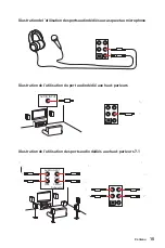
Page 97: ...esportsaudiod di saucasqueetaumicrophone Illustration de l utilisation du port audio d di aux haut parleurs Illustration de l utilisation des ports audio d di s aux haut parleurs 7 1 AUDIO INPUT AUDIO...

Page 98: ...16 Contenu Installation des antennes 1 Vissez fermement les antennes aux connecteurs d di s comme illustr ici 2 Orientez les antennes 1 2...

Page 99: ...JUSB3 SYS_FAN2 JBAT1 JTBT1 JTPM1 JRGB1 SATA 1 2 SATA 3 4 SATA 5 6 JDASH1 M2_2 SYS_FAN1 JUSB4 M2_1 JCI1 JUSB1 CPU_FAN1 PUMP_FAN1 PCI_E1 PCI_E2 PCI_E3 Scoket processeur CPU_PWR1 CPU_PWR2 JRAINBOW2 JAUD...

Page 100: ...appliquer une couche de p te thermique ou adh sif thermique entre le processeur et le syst me de refroidissement afin d am liorer la dissipation de la chaleur Quand le processeur n est pas install pr...

Page 101: ...uence d op ration de m moire d pend du Serial Presence Detect SPD Rendez vous sur le BIOS et choisissez la fonction DRAM Frequency pour r gler la fr quence de m moire si vous voulez faire fonctionner...

Page 102: ...E1 pour profiter de performances optimales Veillez toujours mettre l ordinateur hors tension et d brancher le cordon d alimentation avant d installer les cartes d extension R f rez vous la documentati...

Page 103: ...la plaque M 2 SHIELD FROZR et retirez le film de protection du pad thermique Important La technologie Intel RST supporte seulement un SSD M 2 PCIe avec une m moire ROM UEFI Intel Optane Memory Ready p...

Page 104: ...orer les tapes 3 et 5 3 Fixez l entretoise M 2 fourni de mani re l adapter la longueur du SSD M 2 4 Ins rez votre SSD M 2 dans le slot M 2 un angle de 30 degr s 5 Fixez le SSD M 2 avec la vis M 2 8 5H...

Page 105: ...c bles SATA disposent de prises identiques sur chaque c t N anmoins il est recommand de connecter la prise plate sur la carte m re pour un gain d espace Le connecteur SATA2 est indisponible lorsqu un...

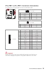
Page 106: ...connecteur est utilis pour connecter un contr leur de r glage selon mod le 1 2 6 5 1 No Pin 2 NC 3 MCU_SMB_SCL_M 4 MCU_SMB_SDA_M 5 VCC5 6 Ground 1 2 10 9 Power LED HDD LED Reset Switch Reserved Power...

Page 107: ...23 5V 12 3 3V 24 Ground 5 4 1 8 CPU_PWR1 1 Ground 5 12V 2 Ground 6 12V 3 Ground 7 12V 4 Ground 8 12V Important Veuillez vous assurer que tous les c bles d alimentation sont branch s aux connecteurs a...

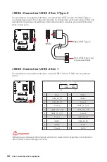
Page 108: ...onnecteur USB 3 2 Gen 1 Ce connecteur vous permet de relier un port USB 3 2 Gen 1 5 Gb s sur le panneau avant Important Notez que les c bles d alimentation et de terre doivent tre branch s correctemen...

Page 109: ...er tout dommage sur la carte m re Pour recharger votre iPad iPhone et iPod par l interm diaire d un port USB veuillez installer l utilitaire MSI Center 1 2 12 11 1 SPI Power 2 SPI Chip Select 3 Master...

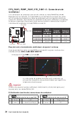
Page 110: ...terner entre le mode PWM et le mode DC et ajuster la vitesse des ventilateurs dans BIOS HARDWARE MONITOR Choisissez le mode PWM ou le mode DC Important Veuillez vous assurer que les ventilateurs fonct...

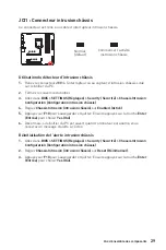
Page 111: ...intrusion ch ssis sur Enabled Activ 5 Appuyez sur F10 pour sauvegarder et quitter Ensuite appuyez sur la touche Enter Entr e pour choisir Yes Oui 6 D sormais si le bo tier du PC est ouvert quand l or...

Page 112: ...our fermer JBAT1 pendant 5 10 secondes 3 Enlevez le couvercle de cavalier du JBAT1 4 Branchez de nouveau le c ble d alimentation votre ordinateur et allumez le EZ Debug LED Ces LEDs indiquent l tat de...

Page 113: ...et d brancher le c ble d alimentation de la prise lectrique Veuillez utiliser un logiciel MSI d di pour contr ler le ruban d extension LED JRGB1 Connecteur LED RGB Le connecteur JRGB vous permet de co...

Page 114: ...retirer le ruban LED RGB veillez toujours teindre l alimentation et d brancher le c ble d alimentation de la prise lectrique Veuillez utiliser un logiciel MSI d di pour contr ler le ruban d extension...

Page 115: ...or DVD 7 Suivez les instructions l cran pour installer Windows 10 Installer les pilotes 1 Allumez l ordinateur sous Windows 10 2 Ins rez la cl USB MSI dans le port USB 3 Cliquez sur la fen tre popup...

Page 116: ...ts de lumi re LED sur les PC et autres produits MSI Avec MSI Center vous pouvez personnaliser les modes selon vos envies surveiller les performances du syst me et r gler la vitesse du ventilateur Guid...

Page 117: ...titions Prend en charge toutes les capacit s de nouveaux appareils les nouveaux appareils peuvent ne pas fournir de compatibilit descendante Prend en charge le d marrage s curis L UEFI peut v rifier l...

Page 118: ...enter Setup Menu F11 to enter Boot Menu sur l cran veuillez appuyer sur la touche Suppr Touches de fonction F1 Liste d aide g n rale F2 Ajouter ou supprimer un l ment favori F3 Entrer dans le menu Fa...

Page 119: ...erni re version de BIOS compatible votre carte m re sur le site MSI Ensuite veuillez sauvegarder le nouveau BIOS sur la cl USB Mettre le BIOS jour 1 Connectez la cl USB contenant le profil au port USB...

Page 120: ...me red marrera automatiquement pour la mise jour du BIOS 6 Une fois la mise jour termin e le syst me red marrera automatiquement Mettre le BIOS jour avec Bouton Flash BIOS 1 Veuillez t l charger la de...

Page 121: ...ATA 6 22 JAUD1 22 JFP1 JFP2 23 JDASH1 23 CPU_PWR1 2 ATX_PWR1 24 JUSB4 USB 3 2 Gen 2 Type C 25 JUSB3 USB 3 2 Gen 1 25 JUSB1 2 USB 2 0 26 JTPM1 26 CPU_FAN1 PUMP_FAN1 SYS_FAN1 2 27 JCI1 28 JBAT1 CMOS BIO...

Page 122: ...2 60 C 140 F...

Page 123: ...3 Case standoff keep out zone...

Page 124: ...2933 Intel 10 JEDEC POR 1R 2133 2666 2933 3200 Intel 11 JEDEC POR 1DPC 1R 5333 1DPC 2R 4700 2DPC 1R 4400 2DPC 2R 4000 non ECC Intel Extreme Memory Profile XMP www msi com 2x PCIe x16 x16 x4 PCI_E1 PC...

Page 125: ...A 6 Z590 2x M 2 M M2_1 Intel 11 PCIe 4 0 x4 2242 2260 2280 M2_2 Z590 PCIe 3 0 x4 SATA 6 2242 2260 2280 Intel Optane Intel Smart Response Intel Core SATA2 M 2 SATA SSD M2_2 Intel Optane BIOS MSI RAID R...

Page 126: ...2 Gen 1 5 4 Type A 2 2x USB 2 0 USB Hub GL850G 4x USB 2 0 Realtek ALC4080 7 1 High Definition Audio S PDIF out LAN 1x 2 5 Intel I225 V Wi Fi Bluetooth WiFi 6E AX210 M 2 E MU MIMO TX RX 2 4 5 6 160 2 4...

Page 127: ...12 1x 4 ATX 12 6x SATA 6 2x M 2 M 1x USB 3 2 Gen 2 10 Type C 1x USB 3 2 Gen 1 5 2 USB 3 2 Gen 1 5 2x USB 2 0 4 USB 2 0 1x 4 1x 4 Water Pump 2x 4 1x 2x 1x 1x TPM 1x CMOS 1x 1x TBT RTD3 1x 4 RGB LED 2x...

Page 128: ...2x2 20 Type C 2x Wi Fi 5x 1x S PDIF OUT NUVOTON NCT6687 R Micro ATX 9 6 x 9 6 24 4 x 24 4 BIOS 1x 256 UEFI AMI BIOS ACPI 6 2 SMBIOS 3 0 MSI Center Intel Extreme Tuning Utility MSI APP Player BlueStac...

Page 129: ...ighlights LAN Manager Mystic Light Ambient Link Frozr AI Cooling User Scenario True Color Live Update Monitor Super Charger Speed Up Audio Boost 5 Sound Tune 2 5G LAN LAN Manager Intel WiFi M 2 Shield...

Page 130: ...LED Lightning Gen 4 PCI E Lightning Gen 4 M 2 Multi GPU CrossFire Technology DDR4 Boost Core Boost GAME Boost Lightning USB 20G USB 3 2 Gen 2 10G USB Type A C USB Type C Dual CPU Power Server PCB 2oz...

Page 131: ...11 MPG Z590M GAMING EDGE WIFI SATA 6 1 USB 1 Wi Fi 1 2 2 1 1 MPG 1 SATA 1 1 1 1 1 1...

Page 132: ...12 2 4 6 8 LAN 10 100 1000 2 5 USB 3 2 Gen 2 10 Type A LAN 2 5 S PDIF Out DisplayPort USB 3 2 Gen 1 5 Type A Flash BIOS USB 2 0 USB 3 2 Gen 2x2 20 Type C Wi Fi Flash BIOS Flash BIOS 36 BIOS Flash BIOS...

Page 133: ...13 Realtek Audio Console Realtek Audio Console...

Page 134: ...14 7 1 AUDIO INPUT AUDIO INPUT Rear Front Side Center Subwoofer...

Page 135: ...15 1 WiFi 2 1 2...

Page 136: ...JTBT1 JTPM1 JRGB1 SATA 1 2 SATA 3 4 SATA 5 6 JDASH1 M2_2 SYS_FAN1 JUSB4 M2_1 JCI1 JUSB1 CPU_FAN1 PUMP_FAN1 PCI_E1 PCI_E2 PCI_E3 CPU_PWR1 CPU_PWR2 JRAINBOW2 JAUD1 JFP2 JRAINBOW1 JPWRLED1 JFP1 ATX_PWR1...

Page 137: ...17 MSI MSI LGA 1200 LGA 1200 1 50 6 DIMM...

Page 138: ...18 DIMM DIMMA1 DIMMB1 A B DIMMA2 DIMMB2 DIMMA2 SPD Serial Presence Detect BIOS DRAM Frequency www msi com DIMMB2 DIMMB2 DIMMB1 DIMMA2 DIMMA2 DIMMA2 DIMMA1...

Page 139: ...Card Bolster PCIe x16 PCI_E1 JTBT1 Thunderbolt Thunderbolt 1 2 16 15 1 TBT_Force_PWR 2 TBT_S0IX_Entry_REQ 3 TBT_CIO_Plug_Event 4 TBT_S0IX_Entry_ACK 5 SLP_S3 _TBT 6 TBT_PSON_Override_N 7 SLP_S5 _TBT 8...

Page 140: ...20 M2_1 2 M 2 M M 2 1 M 2 SHIELD FROZR 2 M 2 SHIELD FROZR 2 2 1 1 1 1 M2_1 M2_2 Intel RST PCIe M 2 SSD UEFI ROM M2_2 Intel Optane M 2 SSD https youtu be 2UeWMgjwogU M2_1 M2_2...

Page 141: ...21 30 30 4 3 6 6 6 6 5 8 5H 3 5 2280 M 2 M2_1 3 M 2 M 2 SSD 4 M 2 SSD 2 30 5 M 2 SSD 8 5H M 2 6 M 2 SHIELD FROZR...

Page 142: ...SATA 6 SATA SATA1 SATA3 SATA5 SATA2 SATA4 SATA6 SATA SATA SATA2 M 2 SATA SSD M2_2 JAUD1 1 2 10 9 1 MIC L 2 Ground 3 MIC R 4 NC 5 Head Phone R 6 MIC Detection 7 SENSE_SEND 8 No Pin 9 Head Phone L 10 He...

Page 143: ...tch JFP1 1 HDD LED 2 Power LED 3 HDD LED 4 Power LED 5 Reset Switch 6 Power Switch 7 Reset Switch 8 Power Switch 9 Reserved 10 No Pin 1 JFP2 Speaker Buzzer 1 Speaker 2 Buzzer 3 Buzzer 4 Speaker JDASH1...

Page 144: ...PS ON 5 Ground 17 Ground 6 5V 18 Ground 7 Ground 19 Ground 8 PWR OK 20 Res 9 5VSB 21 5V 10 12V 22 5V 11 12V 23 5V 12 3 3V 24 Ground 5 4 1 8 CPU_PWR1 1 Ground 5 12V 2 Ground 6 12V 3 Ground 7 12V 4 Grou...

Page 145: ...Gen 1 5 1 10 11 20 1 Power 11 USB2 0 2 USB3_RX_DN 12 USB2 0 3 USB3_RX_DP 13 Ground 4 Ground 14 USB3_TX_C_DP 5 USB3_TX_C_DN 15 USB3_TX_C_DN 6 USB3_TX_C_DP 16 Ground 7 Ground 17 USB3_RX_DP 8 USB2 0 18...

Page 146: ...Ground 9 No Pin 10 NC VCC iPad iPhone iPod USB MSI Center 1 2 12 11 1 SPI Power 2 SPI Chip Select 3 Master In Slave Out SPI Data 4 Master Out Slave In SPI Data 5 Reserved 6 SPI Clock 7 Ground 8 SPI Re...

Page 147: ...lation PWM 12 PWM DC BIOS HARDWARE MONITOR PWM DC PWM DC PWM DC CPU_FAN1 PWM 2 24 PUMP_FAN1 PWM 3 36 SYS_FAN1 2 DC 1 12 1 PWM 1 Ground 2 12V 3 Sense 4 Speed Control Signal 1 DC 1 Ground 2 Voltage Cont...

Page 148: ...JCI1 2 3 BIOS SETTINGS Security Chassis Intrusion Configuration 4 Chassis Intrusion Enabled 5 F10 Enter Yes 6 1 BIOS SETTINGS Security Chassis Intrusion Configuration 2 Chassis Intrusion Reset 3 F10...

Page 149: ...29 JBAT1 CMOS BIOS CMOS CMOS BIOS BIOS 1 2 JBAT1 5 10 3 JBAT1 4 EZ CPU DRAM DRAM VGA BOOT JPWRLED1 JPWRLED1...

Page 150: ...30 JRGB 5050 RGB 12 G R B 2 3 12 RGB MSI JRGB1 RGB LED JRGB 5050 RGB 12 1 G R B JRGB 5050 RGB 12 1 1 12V 2 G 3 R 4 B RGB 1 1 G R B JRGB RGB RGB...

Page 151: ...BOW 5 JRGB JRAINBOW RGB WS2812B 5 Data Ground 3 5 75 20 200 RGB MSI JRAINBOW1 2 RGB LED JRAINBOW RGB WS2812B 5 JRAINBOW JRAINBOW RAINBOW RGB LED RGB WS2812B 5 1 JRAINBOW1 1 JRAINBOW2 1 5V 2 Data 3 No...

Page 152: ...6 Press any key to boot from CD or DVD 7 Windows 10 1 Windows 10 2 USB MSI USB 3 Select to choose what happens with this disc Run DVDSetup exe Windows DVDSetup exe USB MSI USB Drive 4 Drivers Software...

Page 153: ...EFI BIOS UEFI BIOS UEFI BIOS UEFI UEFI BIOS CSM POST 2 4 GUID GPT UEFI UEFI 32 Windows Windows 10 64 There is no GOP Graphics Output protocol support detected in this graphics card GOP UEFI BIOS 1 2 D...

Page 154: ...OS BIOS HELP BIOS BIOS Delete Press DEL key to enter Setup Menu F11 to enter Boot Menu F1 F2 F3 F4 F5 Memory Z F6 F7 EZ F8 F9 F10 F12 USB FAT FAT32 Ctrl F F10 Yes No BIOS BIOS http download msi com ma...

Page 155: ...S BIOS BIOS BIOS F6 CMOS CMOS BIOS CMOS BIOS BIOS M FLASH BIOS MSI BIOS USB BIOS 1 USB USB 2 Ctrl F5 POST Yes Press Ctrl F5 to activate M Flash for BIOS update Del POST BIOS M FLASH Yes 3 BIOS BIOS 4...

Page 156: ...S MSI Center BIOS BIOS 1 MSI Center Support 2 Live Update Advance 3 BIOS Install 4 Install 5 BIOS 6 BIOS Flash BIOS 1 BIOS MSI 2 BIOS MSI ROM USB 3 CPU_PWR1 ATX_PWR1 4 USB MSI ROM Flash BIOS 5 Flash B...

Page 157: ...be applicable RED 2014 53 EU Low Voltage Directive 2014 35 EU EMC Directive 2014 30 EU RoHS Directive 2011 65 EU Compliance with these directives is assessed using applicable European Harmonized Stand...

Page 158: ...equipos electr nicos est n obligados a hacerse cargo de dichos productos al termino de su per odo de vida MSI estar comprometido con los t rminos de recogida de sus productos vendidos en la Uni n Euro...

Page 159: ...rare ogni prodotto alla fine del suo ciclo di vita MSI si adeguer a tale Direttiva ritirando tutti i prodotti marchiati MSI che sono stati venduti all interno dell Unione Europea alla fine del loro ci...

Page 160: ...uracy or completeness is expressed or implied MSI reserves the right to make changes to this document without prior notice Revision History Europe version 1 0 2021 04 First release Technical Support I...

Reviews: