background image

Hardware Setup

2-5

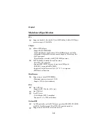
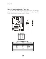
DDR Module Combination

You can install PC1600/PC2100 DDR SDRAM modules into the DDR

DIMM slots (DDR 1~3) in any combination as follows:

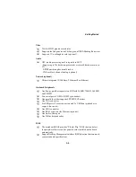
DDR Module Installation Procedure

    1.

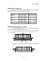
The DDR DIMM has only one notch on the center of module.

The module will only fit in the right orientation.

    2.

Insert the DIMM memory module vertically into the DIMM

slot. Then push it in.

    3.

The plastic clip at each side of the DIMM slot will automatically

close.

Socket

Memory Module Total Memory

DIMM 1

64MB, 128MB,

64MB ~ 512MB

256MB, 512MB

DIMM 2

64MB, 128MB,

64MB ~ 512MB

256MB, 512MB

DIMM 3

64MB, 128MB,

64MB ~ 512MB

256MB, 512MB

Maximum System Memory Supported 64MB ~ 1.5GB

Volt

notch

Summary of Contents for MS-6373

Page 1: ...i Version 1 1 G52 MA00470 MS 6373 v1 X ATX Mainboard MSI K7N420 Pro...

Page 2: ...h the instruction manual may cause harmful interference to radio communications Operation of this equipment in a residential area islikely to cause harmful interference in which case the user will be...

Page 3: ...rademarks All trademarksare the properties oftheir respective owners Intel and Pentium are registered trademarks ofIntel Corporation PS 2 and OS 2 areregistered trademarksof International Business Mac...

Page 4: ...ormodule 9 All cautions and warnings on the equipment should be noted 10 Neverpourany liquid into the opening that could damage the equipment orcause an electrical shock 11 If any ofthe following sit...

Page 5: ...UCore Speed Derivation Procedure 2 3 Memory 2 4 Introduction to DDR 2 4 DDRModuleCombination 2 5 DDR Module InstallationProcedure 2 5 PowerSupply 2 6 ATX20 Pin PowerConnector 2 6 BackPanel 2 7 Mouse C...

Page 6: ...20 ClearCMOSJumper JBAT1 2 20 FSB Mode Jumper SW2 2 21 AudioContorl Jumper JA1 2 22 Keyboard Wake up Jumper JKBV1 2 23 Slots 2 24 AGP Slot 2 24 PCISlots 2 25 CNRSlot 2 25 Chapter 3 AWARDBIOS Setup 3...

Page 7: ...t Setup 3 20 PnP PCIConfigurations 3 24 PC Health Status 3 26 Frequency VoltageControl 3 28 Load High Performance BIOSSetup Defaults 3 29 Set Supervisor User Password 3 30 Appendix DDRDIMMConfiguratio...

Page 8: ...rd K7N420 Pro MS 6373 ATXmainboard is an excellent computer mainboardbased on the innovative nForce 420Dchipset which supports the latest AMD Athlon Athlon XP Duron processor series and provides you w...

Page 9: ...cessor Dual ATA 100 controller SupportUSB UHCI1 0a provide up to sixUSB ports IEEE 802 3 compatibleMAC MII Integrated Audio Processor Unit AC 97 2 1 compliant SPDIFoutput function MainMemory Support u...

Page 10: ...t On boardPeripherals One floppy port that supportstwo FDDwith 360KB 720KB 1 44MB and2 88MB Two serial ports COM A COM 2 pin header One parallelport that supportsSPP EPP ECP modes One VGA connector Si...

Page 11: ...Chapter 1 1 4 Dimension 30 5cmx22 5cm Mounting Sixmountingholes...

Page 12: ...JA1 JAUDIO2 ATX Power Supply SYSFAN1 JBAT1 W inbond W83 627FH AW IR MSIFP SW2 JSP1 SOCKET 462 BIOS PCI Slot 5 PCI Slot 4 PCI Slot 3 PCI Slot 2 PCI Slot 1 IDE2 IDE1 CNR Top Parallel Port Bottom COM A V...

Page 13: ...on monitor CPU system temperatures monitor fan speed s monitor system voltage monitor chassis intrusion If one of the items above is abnormal the program main screen will be immediately shown on the s...

Page 14: ...eatures l Network Management Monitoring remote control l BasicSystemUtilities Scandisk Defragment to maintain your HDD l 3DGraphicsDesign Enablesa more friendly userinterface l SofwareUtilities SoftCo...

Page 15: ...he overclocking users Theseusers can use the feature to detect if there are any problems or failures D Bracket D Bracket Description System Power ON The D LED will hang here if the processor is damage...

Page 16: ...eo adapter BIOS Sign On This will start showing information about logo processor brand name etc Testing Base and Extended Memory Testing base memory from 240K to 640K and extended memory above 1MB usi...

Page 17: ...mn of the screen Click the desired button to start the update process l Live BIOS Updates the BIOS online If your motherboard does not support the function the sorry message is displayed l Live Driver...

Page 18: ...ation procedures For some components if you install in the wrong orientation the components will not work properly Use a grounded wrist strap before handling computer components Static electricity may...

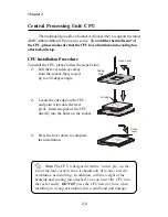
Page 19: ...a 90 degree angle 2 Locate the cut edge on the CPU and point it towards the lever pivot Insert the pins of the CPU directly into the holes on the socket 3 Press the lever down to complete the installa...

Page 20: ...the specified thermal requirements AMD recommends the use of high performance thermal interface material AMD Athlon Athlon XP processors with a speed of 600MHz and above require the LARGER heatsink a...

Page 21: ...DIMM modules used by SDR SDRAM Two types of DDRareavailableatthetimeofwriting PC1600 PC2100 PC1600DDRSDRAM running at 100MHz will produce about 1 6GB s memory bandwidth PC2100 running at 133MHz will...

Page 22: ...enter of module The module will only fit in the right orientation 2 Insert the DIMM memory module vertically into the DIMM slot Then push it in 3 The plastic clip at each side of the DIMM slot will au...

Page 23: ...supports instant power on function which means that system will boot up immediately when the power supply connector is inserted on the board The mainboard supports ATX power supply for the power syste...

Page 24: ...can plug a PS 2 mouse directly into this connector The connector location and pin assignments are as follows PS 2 Mouse 6 pin Female PIN SIGNAL DESCRIPTION 1 Mouse DATA Mouse DATA 2 NC No connection...

Page 25: ...B devices such as keyboard mouse or other USB compatible devices You can plug the USB device directly into ths connector USB Ports 1 2 3 4 5 6 7 8 PIN SIGNAL DESCRIPTION 1 Keyboard DATA Keyboard DATA...

Page 26: ...E 4 N C 5 GND 6 GND 7 GND 8 GND 9 5V 10 GND 11 N C 12 SDA 13 Horizontal Sync 14 Vertical Sync 15 SCL COM2 2 4 6 8 9 1 3 5 7 COMA 1 2 3 4 5 6 7 8 9 PIN SIGNAL DESCRIPTION 1 NDCDB Data carry detect 2 ND...

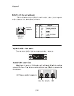
Page 27: ...connector for microphones 1 8 Stereo Audio Connectors Line Out Line In MIC RJ 45 LAN Jack Optional The mainboard provides a RJ 45 connector that allows your computer to be connected to a network envi...

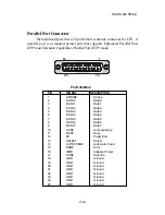
Page 28: ...e 13 1 14 25 PIN SIGNAL DESCRIPTION 1 STROBE Strobe 2 DATA0 Data0 3 DATA1 Data1 4 DATA2 Data2 5 DATA3 Data3 6 DATA4 Data4 7 DATA5 Data5 8 DATA6 Data6 9 DATA7 Data7 10 ACK Acknowledge 11 BUSY Busy 12 P...

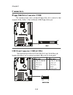
Page 29: ...types Connectors 2 34 1 33 FDD1 USB Front Connector USB3 USB4 The mainboard provides the Front USB Universal Serial Bus pin headers that allow you to connect optional USB ports for front panel 9 1 10...

Page 30: ...vided IDE hard disk cable IDE1 PrimaryIDEConnector The first hard drive should always be connected to IDE1 IDE1 can connect a Master and a Slave drive You must configure second hard drive to Slave mod...

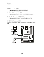
Page 31: ...The connector is for DVD add on card with Line in connector Modem In Connector MODEM1 The connector is for modem with internal audio connector SPDIF OutConnector JSP1 This connector is used to connec...

Page 32: ...to the 12V the black wire is Ground and should be connected to GND If the mainboard has a System Hardware Monitor chipset on board you must use a specially designed fan with speed sensor to take adva...

Page 33: ...odule You must configure the setting through the BIOS setup to use the IR function IR1 1 IR 1 2 6 5 PIN SIGNAL 1 VCC 2 NC 3 IRRX 4 GND 5 IRTX IR1 Pin Definition PIN SIGNAL IN OUT DESCRIPTION 1 Not Ass...

Page 34: ...active LED 4 FP PWR SLP MSG LED pull up 5 RST_SW_N Reset Switch low reference pull down 6 PWR_SW_P Power Switch high reference pull up 7 RST_SW_P Reset Switch high reference pull up 8 PWR_SW_N Power...

Page 35: ...o connect to D Bracket D Bracket is a USB Bracket integrating four LEDs and allows users to identify system problem through 16 various combinations of LED signals For definitions of 16 signal combinat...

Page 36: ...nnect the rear speakers before using the front earphone jack PIN SIGNAL DESCRIPTION 1 AUD_MIC Front panel microphone input signal 2 AUD_GND Ground used by analog audio circuits 3 AUD_MIC_BIAS Micropho...

Page 37: ...e system configuration use the JBAT1 Clear CMOS Jumper to clear data Follow the instructions below to clear the data Jumpers The motherboard provides one jumper for you to set the computer s function...

Page 38: ...while doing the overclocking you can use this jumper to set the safe mode that allows you to reset the system After the computer is reset remember to set to user mode In addition you also need to set...

Page 39: ...udioControlJumper JA1 This jumper is used to control the audio interface The factory default is set to short connected Please do not change the default setting to ensure proper audio outputs Short Def...

Page 40: ...er on function Please note that once the ATX Power Supply cord was unplugged the keyboard wake up password will be cleared Reset the keyboard password to restart the keyboard wake up function JKBV1 1...

Page 41: ...main memory and provides three levels of throughputs 1x 266Mbps 2x 533Mbps and 4x 1 07Gbps The motherboard provides five 32 bit Master PCI bus slots one AGP slot and one CNR slot PCI Slots AGP Slot CN...

Page 42: ...tation for the expansioncard to make any necessary hardware or software settings for the expansion card such as jumpers switches or BIOS configuration CNR Communication Network Riser The CNR slot allo...

Page 43: ...requests you to run SETUP You want to change the default settings for customized features 3 AWARD BIOS Setup TOPICS Entering Setup 3 2 The Main Menu 3 4 Standard CMOS Features 3 6 Advanced BIOS Featu...

Page 44: ...press ing Ctrl Alt and Delete keys TO ENTER SETUP BEFORE BOOT PRESS CTRL ALT ESC Control Keys After entering the BIOS setup program you can use the keyboard to navigate through the setup menus and cha...

Page 45: ...ight thefield and press Enter to call up the sub menu Then you can use the control keys to enter values and move from fieldto field within a sub menu If you want to return to the main menu press the E...

Page 46: ...to enter the sub menu StandardCMOSFeatures Use this menu for basic system configurations AdvancedBIOSFeatures Use this menu to set the items of Award special enhanced features AdvancedChipsetFeatures...

Page 47: ...your settings of frequency voltage control LoadBIOSSetupDefaults Use this menu to load the BIOS default values for the most stable system performance LoadHighPerformance Defaults Use this menu to loa...

Page 48: ...you to set the system to the date that you specify usually the current date The format is day month date year Day Day of the week from Sun to Sat determined by BIOS read only Month The month from Jan...

Page 49: ...tings are CHS LBA Large and Auto Capacity The formatted size of the storage device Cylinder Numberof cylinders Head Number of heads Precomp Write precompensation Landing Zone Cylinderlocation ofthe la...

Page 50: ...happens All But Keyboard The systemwill halt on ifany error happens But the system will not halt on ifthe keyboard function is not normal All But Diskette The systemwill halt on ifany error happens B...

Page 51: ...OST Settings Enabled and Disabled Full Screen Logo Show Thisitemallows you to enable or disable the full screen Logo showcapability Available optionsare Disabled and Enabled CPUInternal Cache Cache me...

Page 52: ...omotherdevice ifthe systemfails to boot from the 1st 2nd 3rd boot device Available options are Disabled and Enabled HDDS M A R T This allowsyou to activate the S M A R T Self Monitoring Analysis Re po...

Page 53: ...Delay can beselected Available options are Disabled and Enabled Typematic Rate Chars Sec This item allows you to set the number of times a second to repeat a key stroke when you hold the key down Avai...

Page 54: ...operating system When set to Non OS2 you can not run the OS 2 operating system when DRAM in stalled is larger than 64 MB When set to OS2 it is possible Available options are Non OS2 and OS2 VideoBIOS...

Page 55: ...ideo RAM resulting in better system performance However if any program writes to thismemory area a system error may result Available options are Enabled and Disabled DDRAMAuto Precharge W R Auto Prech...

Page 56: ...ntrol when MDA Monochrome Display Adapter ac cesses are sent to the AGP device orto PCI bus Available optionsare AGP and PCI AGP Bus Driving Control This filedis used to adjustthe AGPdriving force Sel...

Page 57: ...for advanced control OnChipIDE Channel0 1 The integrated peripheral controller contains an IDE interface with support for two IDE channels Choose Enabled to activate each channel separately IDEPrefetc...

Page 58: ...IDE device sup ports it and your operating environment contains a DMA driver If both your hard drive and software support Ultra DMA select Auto to enable BIOS support MCP AC97 Audio This item allows...

Page 59: ...first and second serial ports Availableoptionsare 3F8 IRQ4 2E8 IRQ3 3E8 IRQ4 2F8 IRQ3 Disabled and Auto UART Mode Select This itemallowsyou to determine which InfraRed IR function of the onboard I O...

Page 60: ...e Select The item allowsyou to select the EPP version by the parallel port when the port is set to EPP or ECP EPP mode Available options are EPP1 7 and EPP1 9 ECPMode UseDMA The item automatically spe...

Page 61: ...ection function IDEHDDBlockMode Blockmode isalso called block transfer multiple commands or multiplesec tor read write If yourIDE hard drive supportsblock mode most new drives do select Enabled for au...

Page 62: ...specifies the power saving modes for ACPI function Available options are S1 POS The S1 state is low powerstate In this state no system context CPU or chipset is lost and the hardware maintainsall syst...

Page 63: ...YNC Blank This selection will cause the system to turn off thevertical and horizontal synchronization ports and write blanks to the video buffer Blank Screen Thisoptiononlywritesblanksto the videobuff...

Page 64: ...onitoring Press Enter to enter the sub menu A similar screen to the followingappears USB Resume from S3 S4 Allows the activity of USB device to wake up the systemfrom S3 or S4 power saving modes Setti...

Page 65: ...ted to I O devices When an I O device needs to gain attention of the operating system it signals this by causing an IRQ to occur After receiving the signal when the operating system is ready the syste...

Page 66: ...ed by the PnP operat ingsystem like Windows98 When set to No BIOSwill initializeall thePnP cards So select Yes if your operating system isPlug Play aware ResetConfigurationData Normally you leave this...

Page 67: ...ourcesControlledBy isset to Manual Press Enter and you will enter the sub menu ofthe items Thisitem listsIRQ 3 4 5 7 9 10 11 12 14 15 forusers to set each IRQa type depending on the type of device usi...

Page 68: ...emwill be activated Available options are 50 C 122 F 53 C 127 F 56 C 133 F 60 C 140 F 63 C 145 F 66 C 151 F 70 C 158 F and Disabled Current SystemTemp CurrentCPUTemperature System fan Power fan CPU fa...

Page 69: ...ShutdownTemperature This itemallows you to set the shutdown temperature level forthe processor When the processor reach the temperature you set this will shutdown the system This function only works...

Page 70: ...t it to Disabled Setting options 0 5 1 00 2 00 and Disabled CPU MEM AGP sFreq This itemspecifies the clock frequency of CPUhost bus DDR RAMbus and AGP bus CPUCLOCKRATIO End users can overclock the pro...

Page 71: ...mance BIOS Setup Defaults The option is forpower or overclocking users only Use of high performance defaults will tighten most timings to in crease the system performance Therefore a high end sys tem...

Page 72: ...This prevents an unauthorized person from changing any part of yoursystem configuration Additionally when a password is enabled you can also require the BIOS to request a password every time your sys...

Page 73: ...we recommend you to use the same DDR DIMM for both slots Population Rules Table 1 Memory Loads Capacity DIMM1 DIMM2 DIMM3 128MB 64MB 1B or 2B 64MB 1B or 2B X 192MB 128MB 1B or 2B 64MB 1B or 2B X 256M...

Page 74: ...16Mx8 128Mb devices ONE BANK 128MB 2B 128MB DDR DIMM using 8 8Mx16 128Mb devices TWOBANKS 256MB 1B 256MB DDRDIMMusing 832Mx8 256Mb devicesor1632Mx4 128Mb devices ONE BANK2 256MB 2B 256MB DDR DIMM usin...

Page 75: ...BPC2100 HyundaiHY5DU28822T H128MBPC2100 WinbondW942516AH 7128MB PC2100 MicronMT46V16M8TG 75128MBPC2100 ToshibaTC59WM807BFT 70 256MBPC2100 WinbondW942508AH 7256MB PC2100 MicronMT46V16M8TG 75A256MBPC210...

Page 76: ...ts and makes a more efficient design BIOS basic input output system On PCs an essential software that contains all the control code of input output interface such as keyboard disk drives etc It execut...

Page 77: ...memory chips whereas a DIMM has 64 bit path DRAM Dynamic RAM A most common type of computer memory It usually uses one transistor and a capacitor to represent a bit As the development of technology th...

Page 78: ...ransmitting data via infrared light waves This enables you to transfer data from one device to another without any cables LAN local area network A computer netwoek that covers a relatively smaller are...

Page 79: ...es etc to see if they are properly connected and operating PS 2 Port A type of port developed by IBM for connecting a mouse or keyboard to a PC The PS 2 port supports a mini DIN plug containing just 6...

Reviews: