background image

Introduction

1-9

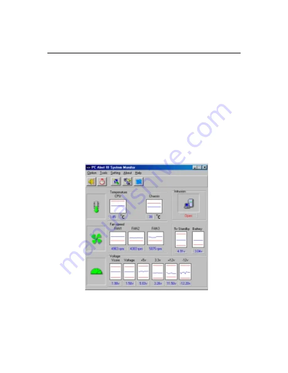
PC Alert™ III

The PC Alert

TM

 III is an utility you can find in the CD-ROM disk.  The

utility is  just like your PC doctor that can detect the following PC hardware

status during real time operation:

     * monitor CPU & system temperatures

     * monitor fan speed(s)

     * monitor system voltage

     * monitor chassis intrusion

If one of the items above is abnormal, the program main screen will be immedi-

ately shown on the screen, with the abnormal item highlighted in red.  This will

continue to be shown,until user disables the warning.

MSI Special Features

Note:

 Items shown on PC Alert III vary depending on your system’s status.


Summary of Contents for MS-6380

Page 1: ...he commu nication bandwidth between the North and South Bridge to 266MB sec through a high speed V Link bus With AGP 4X interface VT8366 boosts system performance for 3D graphics and video program The VT8233 Southbridge integrates many peripheral controllers including dual channel UltraDMA 33 66 100 master mode EIDE controller AC link interface LPC interface USB controller etc The VT8233 is compat...

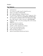
Page 2: ...PI Clock Generator 100 133MHz clocks are supported Main Memory Support six memory banks using three 184 pin DDR DIMMs Support a maximum memory size up to 3GB Support 2 5v DDR SDRAM DIMM Slots One AGP Accelerated Graphics Port or AGP PRO slot AGP specification compliant Support AGP 2 0 1x 2x 4x One CNR Communication Network Riser slot Five 32 bit Master PCI Bus slots Supports 3 3V 5V PCI bus Interf...

Page 3: ... 2 rear ports and 4 ports supported by JUSB2 JUSB3 Audio Chip integrated 2 channel S W audio Direct Sound AC97 Audio On Board Peripherals On Board Peripherals include 1 floppy port supports 2 FDD with 360K 720K 1 2M 1 44M and 2 88Mbytes 2 serial ports COMA COMB 1 parallel port supporting SPP EPP ECP mode 1 IrDA connector for SIR ASKIR HPSIR 1 Audio Game port BIOS The mainboard BIOS provides Plug P...

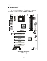
Page 4: ...io Ports JKBV1 CFAN1 ATX Power Supply Socket 462 81 86 Winbond W83627HF AW Codec 4 4 1 1 BATT AGP Slot PCI Slot 2 PCI Slot 3 CNR Slot BIOS SFAN1 81 86 JMDM1 4 PSFAN1 J8 PCI Slot 1 PCI Slot 4 PCI Slot 5 JUSB2 JUSB3 JGL1 JFP1 JBAT1 J6 Diagnostic LED PC2PC Controller MS 6380 provides three types of models to meet consumers diverse needs K7T266 Pro K7T266 Pro R and K7T266 Pro RU ...

Page 5: ... Ports JKBV1 CFAN1 ATX Power Supply Socket 462 81 86 Winbond W83627HF AW Codec 4 4 1 1 BATT AGP Pro Slot PCI Slot 2 PCI Slot 3 CNR Slot BIOS SFAN1 81 86 JMDM1 4 PSFAN1 J8 PCI Slot 1 PCI Slot 4 PCI Slot 5 IDE4 IDE3 PROMISE 20265R JUSB2 JUSB3 JGL1 JFP1 JBAT1 JWR1 J6 Diagnostic LED PC2PC Controller MS 6380 ATX Mainboard K7T266 Pro R ...

Page 6: ... ATX Power Supply Socket 462 81 86 Winbond W83627HF AW Codec 4 4 1 1 BATT AGP Pro Slot PCI Slot 2 PCI Slot 3 CNR Slot BIOS SFAN1 81 86 JMDM1 4 PSFAN1 J8 PCI Slot 1 PCI Slot 4 PCI Slot 5 NEC USB 2 0 Host Controller IDE4 IDE3 PROMISE 20265R JUSB1 JUSB2 JUSB3 JGL1 JFP1 JBAT1 JWR1 J6 Diagnostic LED PC2PC Controller MS 6380 ATX Mainboard K7T266Pro RU ...

Page 7: ...HDD See p 2 14 FDD1 Connecting to floppy disk drive See p 2 12 JUSB1 3 Connecting to USB interfaces See p 2 22 2 26 PCI Slot 1 5 Installing expansion cards See p 2 30 AGP AGP PRO Slot Installing AGP Pro cards See p 2 30 CNR Slot Installing expansion cards See p 2 30 JMDM1 Connecting to modem module See p 2 18 JBAT1 Clearing CMOS data See p 2 28 JFP1 Connecting to case See p 2 15 JGL1 Connecting to...

Page 8: ... Pro R I O 2 serial ports 1 parallel port 4 USB 1 1 4 USB 2 0 ports 1 floppy port 1 IrDA connector 3 Audio 1 Game port for K7T266 Pro RU USB Interface USB 1 1 PC to PC Networking USB 2 0 HC On Board Optional 2 IDE RAID connectors Optional Fuzzy Logic III overclocking utility D LED 4 LEDs embedded in the mainboard PC Alert III system hardware monitor Audio 2 Channel S W audio integrated PCI 2 2 LAN...

Page 9: ...ation monitor CPU system temperatures monitor fan speed s monitor system voltage monitor chassis intrusion If one of the items above is abnormal the program main screen will be immedi ately shown on the screen with the abnormal item highlighted in red This will continue to be shown until user disables the warning MSI Special Features Note Items shown on PC Alert III vary depending on your system s...

Page 10: ...tures Network Management Monitoring remote control Basic System Utilities Scandisk Defragment to maintain your HDD 3D Graphics Design Enables a more friendly user interface Sofware Utilities SoftCooler Optimized Cooling ...

Page 11: ...e Windows environment Select the CPU frequency you prefer and click Go to apply the frequency or click Save allowing the system to run at the specified frequency each time when the system is powered on Features Display Current System Status CPU Fan CPU Temp Vcore Vio Memory Clock CPUClock AGPClock PCIClock Adjust CPU FSB Frequency ...

Page 12: ...lizing Keyboard Controller Testing VGA BIOS This will start writing VGA sign on message to the screen Red Green The D LED uses graphic signal display to help users understand their system Four LEDs embedded in the mainboard provide up to 16 combinations of signals to debug the system The 4 LEDs can debug all problems that fail the system such as VGA RAM or other failures This special feature is ve...

Page 13: ...ter BIOS Sign On This will start showing information about logo processor brand name etc Testing Base and Extended Memory Testing base memory from 240K to 640K and extended memory above 1MB using various patterns Assign Resources to all ISA Initializing Hard Drive Controller This will initialize IDE drive and controller Initializing Floppy Drive Controller This will initializing Floppy Drive and c...

Page 14: ...d follow the installation procedures For some components if you install in the wrong orientation the components will not work properly Use a grounded wrist strap before handling computer components Static electricity may damage the components Central Processing Unit CPU 2 2 Memory 2 5 Power Supply 2 7 Back Panel 2 8 Connectors 2 12 Jumpers 2 28 Slots 2 30 This chapter contains the following topics...

Page 15: ...uld point towards the lever pivot The CPU will only fit in the correct orientation The mainboard supports AMD AthlonTM and DuronTM processor The mainboard uses a CPU socket called Socket A for easy CPU installation Make sure the CPU has a Heat Sink and a cooling fan attached on the top to prevent overheating If you do not find the Heat Sink and cooling fan contact your dealer to purchase and insta...

Page 16: ...the use of high performance thermal interface material AMD Athlon Duron processor with a speed of 600MHz and above re quires LARGER heatsink and fan You also need to add thermal grease be tween the CPU and heatsink to improve heat dissipation Then make sure that the CPU and heatsink are securely fastened and in good contact with each other These are needed to prevent damaging the processor and ens...

Page 17: ...lled on the motherboard refer to Hardware Monitor Setup of BIOS on page 3 26 ThedefaulthardwareconfigurationforCPUClockFrequencyis100MHz Therefore to use a 133MHz CPU you need to adjust the CPU clock up to 133MHz by changing the CPU clock in the BIOS Setup utility While replacing the CPU always turn off the ATX power supply or unplug the power cable of the ATX power supply from grounded outlet fir...

Page 18: ...entional SDRAM only uses the rising edge of the clock to transfer data Therefore conventional SDRAM is called SDR Single Data Rate SDRAM DDR SDRAM uses 2 5 volts as opposed to 3 3 volts used in SDR SDRAM and requires 184 pin DIMM modules rather than 168 pin DIMM modules used by SDR SDRAM DDR SDRAM is also known as SDRAM II DDR DRAM and DSDRAM Double Speed DRAM TwotypesofDDRareavailableatthetimeofw...

Page 19: ...he DDR DIMM has only one notch on the center of module The number of pins on either side of the breaks are different The module will only fit in the right orientation 1 Insert the DIMM module vertically into the DDR DIMM slot Make sure the notch is on the right orientation 2 The plastic clips at sides of the DIMM slot will automatically close Volt Single Sided DIMM Double Sided DIMM ...

Page 20: ...d Then push down the power supply firmly into the connector ATX Power Connector The mainboard supports ATX power supply for the power system Before inserting the power supply connector always make sure that all compo nents are installed properly to ensure that no damage will be caused 10 1 20 11 PIN SIGNAL 11 3 3V 12 12V 13 GND 14 PS_ON 15 GND 16 GND 17 GND 18 5V 19 5V 20 5V PIN SIGNAL 1 3 3V 2 3 ...

Page 21: ... provides a standard PS 2 mouse mini DIN connector for attaching a PS 2 mouse You can plug a PS 2 mouse directly into this connector Back Panel MIC Midi Joystick PS 2 Mouse 6 pin Female 2 1 3 4 5 6 PIN SIGNAL DESCRIPTION 1 Mouse DATA Mouse DATA 2 NC No connection 3 GND Ground 4 VCC 5V 5 Mouse Clock Mouse clock 6 NC No connection Pin Definition ...

Page 22: ...ard mouse or other USB compatible devices You can plug the USB device directly into ths connector 2 1 3 4 5 6 PS 2 Keyboard 6 pin Female PIN SIGNAL DESCRIPTION 1 Keyboard DATA Keyboard DATA 2 NC No connection 3 GND Ground 4 VCC 5V 5 Keyboard Clock Keyboard clock 6 NC No connection Pin Definition USB Ports 1 2 3 4 5 6 7 8 PIN SIGNAL DESCRIPTION 1 VCC 5V 2 Data 0 Negative Data Channel 0 3 Data0 Posi...

Page 23: ...13 1 14 25 PIN SIGNAL DESCRIPTION 1 STROBE Strobe 2 DATA0 Data0 3 DATA1 Data1 4 DATA2 Data2 5 DATA3 Data3 6 DATA4 Data4 7 DATA5 Data5 8 DATA6 Data6 9 DATA7 Data7 10 ACK Acknowledge 11 BUSY Busy 12 P E Paper End 13 SELECT Select 14 AUTOFEED Automatic Feed 15 ERR Error 16 INIT Initialize Printer 17 SLIN Select In 18 GND Ground 19 GND Ground 20 GND Ground 21 GND Ground 22 GND Ground 23 GND Ground 24 ...

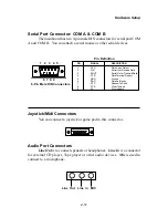
Page 24: ... 3 SOUT Serial Out or Transmit Data 4 DTR Data Terminal Ready 5 GND Ground 6 DSR Data Set Ready 7 RTS RequestToSend 8 CTS Clear To Send 9 RI RingIndicate 9 Pin Male DIN Connectors Pin Definition Joystick Midi Connectors You can connect a joystick or game pad to this connector Audio Port Connectors Line Out is to connect speakers or headphones Line In is a connector for external CD player Tape play...

Page 25: ...s to connect to FDD IDE HDD case modem LAN USB Ports IR module and CPU Power supply System FAN Floppy Disk Drive Connector FDD1 The mainboard provides a standard floppy disk drive connector that supports 360K 720K 1 2M 1 44M and 2 88M floppy disk types Connectors ...

Page 26: ...IDE1 and IDE2 IDE1 PrimaryIDEConnector The first hard disk drive should always be connected to IDE1 You can connect a Master and a Slave drive to IDE1 IDE2 Secondary IDE Connector You can connect a Master and a Slave drive to IDE2 Primary IDE Connector 1 1 Secondary IDE Connector TIP If you install two hard disks on cable you must configure the second drive to Slave mode by setting its jumper Refe...

Page 27: ...e RAID technology for high performance data security and fault tolerance The con nectors support RAID 0 striping and RAID 1 mirroring IDERAIDConnectors You can connect a Master and a Slave drive to each IDE RAID connector FormoreinformationonIDERAID pleaserefertoIDERAIDManual 1 2 39 40 1 2 39 40 IDE3 IDE4 TIP If you install two hard disks on cable you must configure the second drive to Slave mode ...

Page 28: ...1 The case connector block JFP1 allows you to connect to the Power Switch Reset Swtich Keylock Speaker Power LED and HDD LED on the case JFP1 P o w e r Switch P o w e r L E D R e s e t Switch H D D LED Speaker Buzzer short pin 14 15 Keylock ...

Page 29: ...while the system power is on Speaker Speaker from the system case is connected to this pin If on board Buzzer is available then Always short pin 14 15 to enable on board Buzzer HDDLED HDD LED shows the activity of a hard disk drive connected to the IDE1 or IDE2 connector Avoid turning the power off while the HDD is working You can connect the HDD LED from the system case to this pin Keylock Keyloc...

Page 30: ...n ACPI request LED If connected to a 2 pin LED the LED light is green when system in turned on and turns to orange color while entering the sleep state For 3 pin LED the LED is lit when system is on and blinks during the sleep state 1 2 Single Color 1 2 Dual Color 1 3 Blink 3 Pin LED 2 Pin LED Green Color Orange Color Green Color Orange Color JGL1 1 ...

Page 31: ...ill record this status and show a warning message on the screen To clear the warning you must enter the BIOS utility and clear the record J8 JMDM1 Wake On Ring Connector JMDM1 This connector allows you to connect to a modem card with Wake On Ring function The connector will power up the system when a signal is received through the modem card NC MDM_WAKEUP NC 5VSB 1 GND ...

Page 32: ...s you to connect to an IrDA Infrared module You must configure the setting through the BIOS setup to use the IR function J6 1 1 VCC 2 NC 3 IRRX 4 GND 5 IRTX Pin Signal Modem In Connector JMDM The connector is for modem with internal audio connector JMDM GND Mono_Out Phone_In ...

Page 33: ...Chapter 2 2 20 CD In Connector JCD The connector is for CD ROM audio connector Aux Line In Connector JAUX The connector is for DVD add on card with Line in connector JCD JAUX GND L R GND L R ...

Page 34: ...ted to the 12V the black wire is Ground and should be connected to GND If the mainboard has a System Hardware Monitor chipset on board you must use a specially designed fan with speed sensor to take advantage of the CPU fan control Note 1 Always consult the vendor for proper CPU cooling fan 2 CPU Fan supports the fan control You can install the PC Alert utility that will automatically control the ...

Page 35: ...aders one of them will be compatible with USB 1 1 specification and the other will implement USB PC to PC Networking function The mainboard can offer five USB 1 1 ports and one USB PC2PC port 1 9 2 10 Pin Description Pin Description 1 VCC 2 GND 3 USB0 4 GND 5 USB0 6 USB1 7 GND 8 USB1 9 GND 10 VCC JUSB3 Pin Definition JUSB3 USB 1 1 Pin Description Pin Description 1 VCC 2 NC 3 USB0 4 GND 5 USB0 6 US...

Page 36: ...s MP3 players printers modems and the like It is not recommended to connect low speed USB legacy keyboard and mouse to the USB 2 0 ports Please connect these USB legacy devices to the USB rear ports The mainboard can offer seven USB 1 1 ports and one USB PC2PC port 1 9 2 10 JUSB3 USB 2 0 Pin Description Pin Description 1 VCC 2 GND 3 USB0 4 GND 5 USB0 6 USB1 7 GND 8 USB1 9 GND 10 VCC JUSB1 3 Pin De...

Page 37: ...e Optional USB 2 0 Ports 1 Take out the USB 2 0 bracket 2 Locate the JUSB1 and JUSB3 pin headers on the motherboard 3 Connect the USB cables from USB 2 0 bracket to the JUSB1 and JUSB 3 connectors separately 4 Place the USB 2 0 Bracket into the appropriate slot of the system case ...

Page 38: ...any is missing contact your dealer 2 Connect the USB Bracket cable to the JUSB2 pin header on the mainboard Locate the pin hole marked with the ARROW on the con nector of USB Bracket and Pin 2 of JUSB2 Then align the pin hole with Pin 2 to attach the USB Bracket 3 Identify the B Type Connector on the bracket used for PC to PC Net working function JUSB2 Pin Hole marked with ARROW 1 9 2 10 USB PC to...

Page 39: ...ble The transfer rate will run at USB 1 1 speed 12Mbps s For more information on USB PC to PC Networking function refer to Appendix A USB PC to PC Networking Function Connect to the B Type Connector on your PC Connect to the USB 1 1 port of another PC B Type Connector ...

Page 40: ...WR1 Optional This 12V power connector is used to connect the power cable of the AGP Pro card if the card comes with a power cable and supply power to the installed card accordingly ATX 12V Power Connector 1 3 2 4 PIN SIGNAL 1 GND 2 GND 3 12V 4 12V ...

Page 41: ...of system configuration With the CMOS RAM the system can automatically boot OS every time it is turned on That battery has long life time for at least 5 years If you want to clear the system configuration use the JBAT1 Clear CMOS Jumper to clear data Follow the instructions below to clear the data Jumpers 1 The motherboard provides the following jumpers for you to set the computer s function This ...

Page 42: ... you should also go to BIOS to enable the PS 2 keyboard mouse wake up power on function JKBV1 1 VCC 5V Disable Keyboard Power On Function 5V StandBy Default Enable Keyboard Power On Function 3 1 3 1 Note To be able to use this function you need a power supply that provides enough power for this feature Power supply with 750mA 5V Stand by ...

Page 43: ... allow you to insert the expansion cards to meet your needs When adding or removing expansion cards make sure that you unplug the power supply first Meanwhile read the documentation for the expansion card to make any necessary hardware or software settings for the expansion card such as jumpers switches or BIOS configuration CNR Communication Network Riser The CNR specification is an open industry...

Page 44: ...ainboard supports PCI Slot 1 5 Bus Master PCI Interrupt Request Routing The IRQ abbreviation of interrupt request line and pronounced I R Q are hardware lines over which devices can send interrupt signals to the microprocessor To install a PCI expansion card on a PCI shared slot you must make sure the card s driver supports IRQ shared function or there is no need to assign an IRQ to the device The...

Page 45: ...with the overview of the BIOS Setup program It contains the following topics Entering Setup 3 2 Control Keys 3 2 Getting Help 3 3 The Main Menu 3 4 Standard CMOS Features 3 6 Advanced BIOS Features 3 8 Advanced Chipset Features 3 12 Power Management Setup 3 16 PNP PCI Configurations 3 20 Integrated Peripherals 3 22 Hardware Monitor Setup 3 26 Load Performance Optimized Defaults 3 28 Supervisor Use...

Page 46: ... by simultaneously pressing Ctrl Alt and Delete keys Control Keys Move to the previous item Move to the next item Move to the item in the left hand Move to the item in the right hand Enter Select the item Esc Jumps to the Exit menu or returns to the main menu from a submenu PU Increase the numeric value or make changes PD Decrease the numeric value or make changes F5 Restore the previous CMOS valu...

Page 47: ... displayed on the bottom of the screen Default Settings The BIOS setup program contains two kinds of default settings the Optimized and Performance defaults High System Performance Optimized defaults pro vide optimum and stable performance settings for all devices and the system The default value described in the chapter usually refers to the Optimized defaults unless otherwise specified Performan...

Page 48: ... AMI special enhanced features AdvancedChipset Features Use this menu to change the values in the chipset registers and optimize your system s performance AMIBIOS SIMPLE SETUP UTILITY VERSION 1 44 C 2001 American Megatrends Inc All Rights Reserved Standard CMOS Features Advanced BIOS Features Advanced Chipset Features Power Management Setup PNP PCI Configurations Integrated Peripherals Hardware Mo...

Page 49: ... to adjust CPU clock core voltage ratio and DDR voltage High System Performance Use this menu to load the BIOS values for the best system performance but the system stability may be affected Load OptimizedDefaults Use this menu to load factory default settings into the BIOS for optimal and stable system performance operations Supervisor Password Use this menu to set Supervisor Password User Passwo...

Page 50: ...S SETUP menu are divided into 9 categories Each category includes none one or more setup items Use the arrow keys to highlight the item you want to modify and use the PgUp or PgDn keys to switch to the value you prefer AMIBIOSSETUP STANDARDCMOSSETUP C 2001 American Megatrends Inc All Rights Reserved ESC Exit Select Item PU PD Modify Shift F2 Color Date mm dd yyyy Tue May 08 2001 Time hh mm ss 00 0...

Page 51: ... B This item allows you to set the type of floppy drives installed Available options are Not Installed 360 KB 5 1 2 MB 5 720 KB 3 1 44 MB 3 or 2 88 MB 3 The default value for Floppy Drive A is 1 44 MB 3 and for Floppy Drive B is Not Installed Boot Sector Virus Protection The item is to set the Virus Warning feature for IDE Hard Disk boot sector protection When Enabled BIOS will issue a virus warni...

Page 52: ...will boot from the fourth HDD Floppy The system will boot from floppy drive ARMD ZIP The system will boot from LS 120 ZIP 100 ZIP 250 AMIBIOSSETUP BIOSFEATURESSETUP C 2001 American Megatrends Inc All Rights Reserved ESC Quit Select Item F1 Help PU PD Modify F5 Load Previous Values F6 Load Fail Safe Defaults F7 Load Optimized Defaults Quick Boot Enabled 1st Boot Device Floppy 2nd Boot Device IDE 0 ...

Page 53: ...s Reporting Technology capability for the hard disks S M A R T is a utility that monitors your disk status to predict hard disk failure This gives you an opportunity to move data from a hard disk that is going to fail to a safe place before it becomes offline Settings are Enabled and Disabled default BootUpNum Lock This item is to set the Num Lock status when the system is powered on Setting to On...

Page 54: ...value is No L1 L2 Cache The items enable or disable the L1 internal and L2 external cache memory for CPU Setting to Enabled will speed up the system performance System BIOS Cacheable AMIBIOS always copies the system BIOS from ROM to RAM for faster execution Selecting Enabled allows the contents of F0000h RAM memory segment to be written to and read from cache memory Settings are Enabled and Disabl...

Page 55: ... specified ROM is not copied to RAM Enabled The contents of specified ROM are copied to RAM for faster system performance Cached The contents of specified ROM are not only copied to RAM the contents of the ROM area can be writ ten to and read from cache memory ...

Page 56: ...he clock frequency of the installed SDRAM Settings are HCLK The DRAM clock will be equal to the Host Clock AMIBIOSSETUP CHIPSETFEATURESSETUP C 2001 American Megatrends Inc All Rights Reserved ESC Quit Select Item F1 Help PU PD Modify F5 Load Previous Values F6 Load Fail Safe Defaults F7 Load Optimized Defaults Configure SDRAM Timing by SPD SDRAM Frequency HCLK SDRAM CAS Latency 2 5 SDRAM Bank Inte...

Page 57: ...fter receiving it Settings are 2 and 2 5 2 increases the system performance while 2 5 provides more stable performance The default value is 2 5 SDRAMBankInterleave This field selects 2 bank or 4 bank interleave for the installed SDRAM Disable the function if 16MB SDRAM is installed Settings are Disabled 2 Way and 4 Way The default value is Disabled SDRAM1TCommand This item controls the SDRAM comma...

Page 58: ... AGP Read Synchronization feature Settings are Enabled and Disabled AGP Aperture Size The field selects the size of the Accelerated Graphics Port AGP aperture Aperture is a portion of the PCI memory address range dedicated for graphics memory address space Host cycles that hit the aperture range are forwarded to the AGP without any translation Settings are 4MB 8MB 16MB 32MB 64MB 128MB and 256MB AG...

Page 59: ...r to support delayed transactions cycles Select Enabled to support compliance with PCI specification version 2 1 Settings are Enabled and Disabled default BIOS Protection Setting to Enabled will prevent BIOS from performing any BIOS update flash utility Settings are Enabled default and Disabled ...

Page 60: ...d open applica tions files is saved to main memory that remains AMIBIOSSETUP POWERMANAGEMENTSETUP C 2001 American Megatrends Inc All Rights Reserved ESC Quit Select Item F1 Help PU PD Modify F5 Load Previous Values F6 Load Fail Safe Defaults F7 Load Optimized Defaults IPCA Function Yes ACPI Standby State S1 POS USB Wakeup From S3 Disabled Power Management APM Enabled Green PC LED Status DualColor ...

Page 61: ...d and Disabled The default value is Enabled Green PC LED Status This item configures how the system uses sleep state LED on the case to indicate the sleep state Available options are Blinking The sleep state LED blinks to indicate the sleep state Not Changed The sleep state LED remains the same color Dual Color The sleep state LED changes its color to indicate the sleep state The default value is ...

Page 62: ...emperature This item is used to specify a thermal limit for CPU If CPU temperature reaches the specified limit the system will issue a warning to prevent the CPU overheat problem Settings are Disabled 70 C 158 75 C 167 F 80 C 176 F 85 C 185 F 90 C 194 F and 95 C 203 F PowerButtonFunction This feature sets the function of the power button Settings are On Off The power button functions as normal on ...

Page 63: ... Wake Up On Ring function Resume By Alarm This is used to enable or disable the feature of booting up the system on a scheduled time date from the soft off S5 state Settings are Enabled and Disabled AlarmDate Hour Minute Second If Resume By Alarm is set to Enabled the system will automatically resume boot up on a specific date hour minute second specified in these fields Available settings for eac...

Page 64: ...d for booting VGA IDE SCSI The rest of the cards will be initialized by the PnP operat ing system like Windows 98 2000 or ME When set to NO BIOS will initialize all the PnP cards Select Yes if the operating system is Plug Play aware AMIBIOSSETUP PNP PCICONFIGURATION C 2001 American Megatrends Inc All Rights Reserved ESC Quit Select Item F1 Help PU PD Modify F5 Load Previous Values F6 Load Fail Saf...

Page 65: ...le by the system BIOS The available DMA pool is determined by reading the ESCD NVRAM If more DMAs must be removed from the pool the end user can reserve the DMA by assigning an ISA EISA setting to it The default value is PnP IRQ 3 4 5 7 9 10 11 14 15 These items specify the bus where the specified IRQ line is used The settings determine if AMIBIOS should remove an IRQ from the pool of available IR...

Page 66: ...Auto Serial Port2 Mode Normal IR Duplex Mode Half Duplex IR Pin Select IRRX IRTX Parallel Port Auto Parallel Port Mode ECP EPP Version N A Parallel Port IRQ Auto Parallel Port DMA Auto OnBoard Midi Port Disabled Midi IRQ Select 5 OnBoard Game Port 200 Keyboard PowerOn Function Disabled Specific Key for PowerOn N A Mouse PowerOn Function Disabled IDE Function Both OnChip AC 97 Audio Enabled OnChip ...

Page 67: ...gs are Half Duplex and Full Duplex The default is Half Duplex IR Pin Select Set to IRRX IRTX when using an internal IR module connected to the IR J6 connector Set to SINB SOUTB when connecting an IR adapter to COM B Parallel Port This field specifies the base I O port address of the onboard parallel port Selecting Auto allows AMIBIOS to automatically determine the correct base I O port address Set...

Page 68: ...used to specify the address for the onboard Game Port KeyboardPowerOnFunction This controls how and whether the PS 2 keyboard is able to power on the system Settings are Disabled PowerKey Any Key and Specific Key Specific Key for PowerOn This item allows you to specify a password for powering on the system when the Keyboard PowerOn Function is set to Specific Key MousePowerOnFunction This controls...

Page 69: ...led Disable the controller if you want to use other controller cards to connect modems Settings are Auto Disabled and Enabled The default value is Auto USB Controller This is used to enable or disable the USB ports Settings are All USB Port Disabled USB 1 USB 2 USB 1 2 USB 3 USB 1 3 and USB 2 3 The default is All USB Port USBLegacySupport Set to Keyboard or Keyb Mouse if your need to use an USB ke...

Page 70: ...PU is 100MHz you are allowed to Hardware Monitor Setup This section describes how to set the Chassis Intrusion feature CPU FSB frequency monitor the current hardware status including CPU system temperatures CPU System Fan speeds Vcore etc Monitor function is available only if there is hardware monitoring mechanism onboard AMIBIOSSETUP HARDWAREMONITORSETUP C 2001 American Megatrends Inc All Rights ...

Page 71: ...for long term purpose DDR Vcore V The item is to adjust the DDR voltage DDR Vcore to increase the DDR rate Modifying the setting may lead to unstable system so changing the DDR Vcore for long term use is not recommended Chassis Intrusion The field enables or disables the feature of recording the chassis intrusion status and issuing a warning message if the chassis is opened To clear the warning me...

Page 72: ...ights Reserved Standard CMOS Features Advanced BIOS Features Advanced Chipset Features Power Management Setup PNP PCI Configurations Integrated Peripherals Hardware Monitor Setup High System Performance Load Optimized Defaults Supervisor Password User Password IDE HDD AUTO Detection Save Exit Setup Exit Without Saving ESC Quit Select Item F10 Save Exit After enabling this item failed please clear ...

Page 73: ... Power Management Setup PNP PCI Configurations Integrated Peripherals Hardware Monitor Setup High System Performance Load Optimized Defaults Supervisor Password User Password IDE HDD AUTO Detection Save Exit Setup Exit Without Saving ESC Quit Select Item F10 Save Exit Load Optimized Defaults except Standard CMOS SETUP Load Optimized Defaults Y N N Pressing Y loads the default values that are facto...

Page 74: ...screen Type the password up to six characters in length and press Enter The password typed now will clear any previously set password from CMOS memory You will be prompted to confirm the password Retype the password and press Enter You may also press Esc to abort the selection and not enter a password To clear a set password just press Enter when you are prompted to enter the password A message wi...

Page 75: ...red is the PASSWORD CHECK option of the ADVANCED BIOS FEATURES menu If the PASSWORD CHECK option is set to Always the password is required both at boot and at entry to Setup If set to Setup password prompt only occurs when you try to enter Setup About Supervisor Password User Password Supervisor password Can enter and change the settings of the setup menu User password Can only enter but do not ha...

Page 76: ... Megatrends Inc All Rights Reserved ESC Exit Select Item PU PD Modify Shift F2 Color Date mm dd yyyy Tue May 08 2001 Time hh mm ss 00 00 00 Pri Master Auto Pri Slave Auto Sec Master Auto Sec Slave Auto Floppy Drive A 1 44 MB 3 Floppy Drive B Not Installed Boot Sector Virus Protection Disabled TYPE SIZE CYLS HEAD PRECOMP LANDZ SECTOR MODE Base Memory 640 Kb Other Memory 384 Kb Extended Memory 127 M...

Page 77: ...ystem Performance Load Optimized Defaults Supervisor Password User Password IDE HDD AUTO Detection Save Exit Setup Exit Without Saving ESC Quit Select Item F10 Save Exit Save Data to CMOS Exit SETUP When you want to quit the Setup menu you can select this option to save the changes and quit A message as below will appear on the screen Typing Y will allow you to quit the Setup Utility and save the ...

Page 78: ... High System Performance Load Optimized Defaults Supervisor Password User Password IDE HDD AUTO Detection Save Exit Setup Exit Without Saving ESC Quit Select Item F10 Save Exit Abandon all Datas Exit SETUP When you want to quit the Setup menu you can select this option to abandon the changes A message as below will appear on the screen Typing Y will allow you to quit the Setup Utility without savi...

Page 79: ...r 4 VIA Chipset Driver The chapter describes how to install the VIA chipset and AC97 audio drivers and the basic system requirements This chapter contains the following topics Overview 4 2 Driver Installation 4 3 VIA Chipset Driver ...

Page 80: ...o Features AC 97 audio support for SoundBlaster Pro FM synthesis legacy audio System Requirements This section describes system requirements for the VIA driver installation and usage Computer AMD Athlon Duron processor or higher Monitor VGASupport minimum640x480resolution Operating system DOS 5 0 or higher Windows 95 98SE Win dows NT3 51 or 4 0 or OS 2 Windows 2000 or Windows ME CD ROM Double Spee...

Page 81: ...en will show four drivers VIA Atapi Vendor Support Driver AGP VxD Driver IRQ Routing Miniport Driver and VIA INF Driver 1 XX Select all four drivers and click on Next 6 The setup program will request you to choose Install VIA Atapi Vendor Support Driver Select Install and click Next to continue 7 Select Click to enable DMA Mode and click Next to continue 8 The setup program will request you to cho...

Page 82: ...box 5 VIA Bus Master Ultra ATA Driver Windows 2000 AGP VxD Driver and VIA INF Driver 1 XX Select all and click Next to proceed 6 The screen will show a VIA Bus Master Ultra ATA Driver dialog box Select Install and click Next 7 The screen will show a VIA GART AGP Driver 4 XX dialog box Select Install AGP 4X 133 driver and click Next 8 There is a Read Only File Detected dialog box Click Yes A dialog...

Page 83: ...the VIA AC 97 Audio Controller WDM Driver Click Yes to proceed 6 Click Finish to complete setup Windows ME Installing VIA Chipset Driver 1 Insert the supplied CD disk into the CD ROM drive 2 The CD will auto run and the setup screen will appear 3 Click on VIA Chipset Drivers and the screen will show VIA Service Pack 4 XX 4 Click Next and the screen will show a VIA Service Pack 1 README dialog box ...

Page 84: ...ext and the screen will show the VIA Service Pack 1 README dialog box 5 Click Yes to proceed and then select Install to enable Ultra DMA for IDE Driver 6 The Choose Destination Location dialog box appears Click Next 7 The Select Program Folder dialog box appears Click Next 8 Please click on Yes I want to restart my computer and then click Finish to restart your computer and complete installation N...

Page 85: ...r Uninstall in the screen Select Install and click Next 5 The setup program will show the following message on the screen Then click OK 6 Follow the steps shown in Step 5 to finish the VIA AC97 PCI Audio Drivers Installation 7 A window will appear asking Do you want to install the joystick driver for the Microsoft Sidewinder 3D Pro Joystick Please click No to continue 8 Please click Finish to rest...

Page 86: ...his Ethernet emulation environment a name USB PC to PC USB PC to PC supports TCP IP NetBEUI and IPX protocols These features make your PCs able to share their resources such as files or printers to each other Furthermore USB PC to PC also gives you the ability of connecting to your existing Home or Office LAN for network resource or Internet sharing The section includes the following topics Instal...

Page 87: ...o restart my computer now and click FInish button to reboot your computer for updating your driver configuration After you complete the installation procedures you ll find Setup Program has installed GeneLinkTM network driver in your computer It binds TCP IP NetBEUI and IPX protocols to GeneLinkTM device Step 2 Connect your PCs via the USB PC to PC cable Step 3 Network Login When you restart your ...

Page 88: ...EUI or IPX for connecting GeneLinkTM LAN to existing Home Office LAN 2 If you ve already configured your IPX SPX and Client for Netware Networks before installing GeneLinkTM driver we strongly recommend that you should also install Software Router while installing GeneLinkTM driver into your system ...

Page 89: ...w to share your files folders drives and printers a Go to the file folder drive or printer that you want to share b Right click your mouse pointer on the resource you want to share you ll see a POP UP Menu c Select Sharing and you ll see another POP UP Menu ...

Page 90: ...outer is respon sible for handling all network packets between USB PC to PC and your Home Office LAN So only the computer that is physically connected to both LANs needs to install GeneLinkTM Software Router i e this computer should install both GeneLinkTM LAN and one network adapter for Home Office LAN For those computers on USB PC to PC you only need to follow installation procedures on the manu...

Page 91: ...d to internet c All clients which would like to access Internet resources through USB cable should have installed GeneLinkTM driver Now we need to make some network configurations on the Desktop Notebook which connect to GeneLinkTM Software Router to make your Internet access possible maybe you need to consult you Network Adminis trator for doing that a If your existing home office network is NOT ...

Page 92: ...A 7 USB PC to PC Networking Function Click on Properties you ll see another menu Choose TCP IP in Configuration tag and then press Proper ties button You ll see TCP IP Properties menu ...

Page 93: ...e for your computer if it doesn t have and fill in the name of your workgroup If you are not sure what s the name of your compu ter or Workgroup please consult your Network Administrator Press OK to complete your network configuration Restart your computer and you ll be ready to connect to Internet b If your existing HOME OFFICE network is using DHCP to assign client s IP address your Network Seve...

Page 94: ...neLinkTM driver we strongly recommend that you should also install Software Router when you install GeneLinkTM driver into your system If you decide not to install Software Router then the OS will not allow two IPX SPX configurations co exist in the same system This will cause GeneLinkTM Driver Install Program overwrite your original IPX SPX configuration and make your original network configurati...

Page 95: ... is available in Windows 98SEandME To access internet through another computer with modem you need to setup Internet Connection Sharing on all computers connected via USB PC to PC cables Instructions are as follows a Go to Control Panel b Double click Add Remove Programs and the Add Remove Programs Properties window appears c Select Windows Setup tag and double click PC with modem installed Your P...

Page 96: ...A 11 USB PC to PC Networking Function Communications The Communications window appears d Check Internet Connection Sharing and click OK e The Home Networking Wizard starts Click Next ...

Page 97: ...k Adapter from the pull down menu Click Next Note For the computer with a modem installed you need to select My Connection instead of GeneLink Network Adapter on the step and after finishing installation of My Connection select GeneLink Network Adapter when the above window returns g Continue to click Next ...

Page 98: ...r Note In Windows 98SE you can access internet through the shared connection of another computer but it is unable for you to control the remote modem However in Windows ME you are allowed to dial the remote modem of another computer using the dialing program built in Windows ...

Page 99: ...nnector you can connect a D Bracket to J11 D Bracket is a USB Bracket integrating four LEDs whose functions are similar to D LED and allows users to identify system problem through 16 various combinations of LED signals For definitions of 16 signal combinations refer to page 1 12 D LED J11 1 9 2 10 D Bracket 1 2 3 4 Connected to J11 Connected to JUSB2 ...

Reviews: