background image

Chapter 3

3-18

Power Management Features

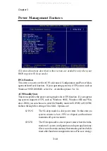
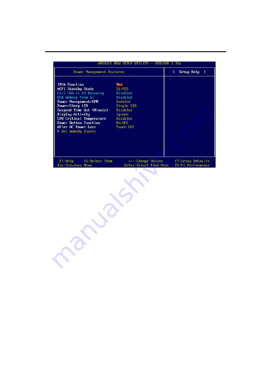
IPCA Function

This item is to activate the ACPI (Advanced Configuration and Power Man-

agement Interface) function.  If your operating system is ACPI-aware, such as

Windows 98SE/2000/ME, select 

Yes

.  Available options: 

Yes

No

.

ACPI Standby State

This item specifies the power saving modes for ACPI function.  If your operat-

ing system supports ACPI, such as Windows 98SE, Windows ME and Win-

dows 2000, you can choose to enter the Standby mode in S1(POS) or S3(STR)

fashion through the setting of this field.  Options are:

S1/POS

The S1 sleep mode is a low power state.  In this state, no

system context is lost (CPU or chipset) and hardware

maintains all system context.

S3/STR

The S3 sleep mode is a lower power state where the infor-

mation of system configuration and open applications/

files is saved to main memory that remains powered while

most other hardware components turn off to save energy.

(S3-related functions described in this section are available only when your

BIOS supports S3 sleep mode.)

All manuals and user guides at all-guides.com

Summary of Contents for MS-6380E

Page 1: ...i MSI Version 1 2 G52 MA00636 MS 6380E v1 X ATX Mainboard K7T266 Pro2 A MICRO STAR INTERNATIONAL All manuals and user guides at all guides com a l l g u i d e s c o m...

Page 2: ...may cause harmful interference to radio communications Operation of this equipment in a residential area is likely to cause harmful interference in which case the user will be required to correct the...

Page 3: ...ies of their respective owners AMD Athlon and Duron are registered trademarks of AMD Corporation PS 2 and OS 2 are registered trademarks of International Business Machines Corporation Windows 98 2000...

Page 4: ...nd warnings on the equipment should be noted 10 Never pour any liquid into the opening that could damage or cause electri cal shock 11 If any of the following situations arises get the equipment check...

Page 5: ...ue for CPU 2 3 CPU Core Speed Derivation Procedure 2 4 CPU Clock Frequency Selection through BIOS 2 4 Memory 2 5 Introduction to DDR SDRAM 2 5 DIMM Module Combination 2 6 Installing DDR Modules 2 6 Po...

Page 6: ...Front Panel Connector JUSB2 2 20 D Bracket Connector JLED 2 21 Jumpers 2 22 Clear CMOS Jumper JBAT1 2 22 Slots 2 23 AGP Accelerated Graphics Port Slot 2 23 PCI Slots 2 23 CNR Communication Network Ris...

Page 7: ...3 22 Integrated Peripherals 3 24 PC Health Status 3 27 Frequency Voltage Control 3 28 Set Supervisor User Password 3 30 Load High Performance BIOS Setup Defaults 3 31 Glossary G 1 All manuals and use...

Page 8: ...VT8233A chipsets for optimal system performance Designed to fit the advanced AMD Athlon Athlon XPor Duron PGA processor in the 462 pin package the K7T266 Pro2 A delivers a high performance and profes...

Page 9: ...ntroller ACPI Clock Generator 100 133MHz clocks are supported MainMemory Supports six memory banks using three 184 pin DDR DIMMs Supports a maximum memory size up to 3GB Supports 2 5V DDR SDRAM DIMM S...

Page 10: ...me port 1 D Bracket pinheader USBInterface Supports USB 1 1 Audio 2 Channel AC 97 S W audio BIOS The mainboard BIOS provides Plug Play BIOS which detects the pe ripheral devices and expansion cards of...

Page 11: ...IOS PCI Slot 5 PCI Slot 4 PCI Slot 3 PCI Slot 2 PCI Slot 1 IDE 1 IDE 2 CNR JBAT1 JLED JFP2 JFP1 JMDM1 JIR1 USB ports Top Parallel Port Bottom COM A COM B Top mouse Bottom keyboard CFAN1 NBFAN1 PSFAN1...

Page 12: ...p 2 12 FDD1 Floppy disk drive connector See p 2 13 IDE1 IDE2 Hard disk connectors See p 2 14 CFAN1 SFAN1 PSFAN1 Fan power connectors See p 2 15 NBFAN1 JIR1 IrDA infrared module connector See p 2 16 J...

Page 13: ...temperatures monitor fan speed s monitor system voltage monitor chassis intrusion If one of the items above is abnormal the program main screen will be immediately shown on the screen with the abnorma...

Page 14: ...y increase the testing value until the PC reboots After rebooting click Turbo to apply the test result Click Default to restore the default values Features l MSI Logo links to the MSI Web site l CPU S...

Page 15: ...users These users can use the feature to detect if there are any problems or failures Red Green D Bracket D Bracket Description System Power ON The D LED will hang here if the processor is damaged or...

Page 16: ...tart showing information about logo processor brand name etc Testing Base and Extended Memory Testing base memory from 240K to 640K and extended memory above 1MB using various patterns Assign Resource...

Page 17: ...screen will appear Five buttons are placed on the leftmost pane of the screen Click the desired button to start the update process l l l l l Live BIOS Updates the BIOS online l l l l l Live Driver Upd...

Page 18: ...llation procedures For some components if you install in the wrong orientation the components will not work properly Use a grounded wrist strap before handling computer components Static electricity m...

Page 19: ...and install them before turning on the computer 1 Pull the lever sideways away from the socket Then raise the lever up to a 90 degree angle 2 Look for the cut edge The cut edge should point to wards...

Page 20: ...Athlon XP processor with a speed of 600MHz and above requires LARGER heatsink and fan You also need to add thermal grease between the CPU and heatsink to improve heat dissipation Then make sure that t...

Page 21: ...ratio 7 then CPU core speed Host Clock x Core Bus ratio 100MHzx7 700MHz WARNING Replacing CPU While replacing the CPU always turn off the ATX power supply or unplug the power supply s power cord from...

Page 22: ...R DIMM Slots DDR 1 3 Introduction to DDR SDRAM DDR Double Data Rate SDRAM is similar to conventional SDRAM but doubles the rate by transferring data twice per cycle It uses 2 5 volts as opposed to 3 3...

Page 23: ...n the right orientation 2 Insert the DIMM memory module vertically into the DIMM slot Then push it in until the golden finger on the memory module is deeply inserted in the socket 3 The plastic clip a...

Page 24: ...er supply firmly into the connector The mainboard supports ATX power supply for the power system Be fore inserting the power supply connector always make sure that all compo nents are installed proper...

Page 25: ...ug a PS 2 mouse directly into this connector The connector location and pin assignments are as follows PIN SIGNAL DESCRIPTION 1 MouseDATA MouseDATA 2 NC Noconnection 3 GND Ground 4 VCC 5V 5 Mouse Cloc...

Page 26: ...ible devices You can plug the USB device directly into the connector PIN SIGNAL DESCRIPTION 1 VCC 5V 2 Data 0 Negative Data Channel 0 3 Data0 Positive Data Channel 0 4 GND Ground 5 VCC 5V 6 Data 1 Neg...

Page 27: ...ial devices directly to the connectors PIN SIGNAL DESCRIPTION 1 DCD Data Carry Detect 2 SIN Serial In or Receive Data 3 SOUT Serial Out or Transmit Data 4 DTR Data Terminal Ready 5 GND Ground 6 DSR Da...

Page 28: ...AL DESCRIPTION 1 STROBE Strobe 2 DATA0 Data0 3 DATA1 Data1 4 DATA2 Data2 5 DATA3 Data3 6 DATA4 Data4 7 DATA5 Data5 8 DATA6 Data6 9 DATA7 Data7 10 ACK Acknowledge 1 1 BUSY Busy 12 PE PaperEnd 13 SELECT...

Page 29: ...s a connector for Speakers or Headphones Line In is used for external CD player Tape player or other audio devices Mic is a connector for microphones 1 8 Stereo Audio Connectors Line Out Line In MIC A...

Page 30: ...e modem LAN USB Ports IR module and CPU System Power Supply FAN Floppy Disk Drive Connector FDD1 The mainboard provides a standard floppy disk drive connector that supports 360K 720K 1 2M 1 44M and 2...

Page 31: ...rimaryIDEConnector The first hard drive should always be connected to IDE1 IDE1 can connect a Master and a Slave drive You must configure second hard drive to Slave mode by setting the jumper accordin...

Page 32: ...black wire is Ground and should be connected to GND If the mainboard has a System Hardware Monitor chipset on board you must use a specially designed fan with speed sensor to take advantage of the CP...

Page 33: ...C5 4 GND 5 IRTX 6 IRRX JIR1 Pin Definition Chassis Intrusion Switch Connector J3 This connector is connected to a 2 pin chassis switch If the chassis is opened the switch will be short The system will...

Page 34: ..._LED_N Hard disk active LED 4 FP PWR SLP MSG LED pull up 5 RST_SW_N Reset Switch low reference pull down to GND 6 PWR_SW_P Power Switch high reference pull up 7 RST_SW_P Reset Switch high reference pu...

Page 35: ..._R Right channel audio signal to front panel 6 AUD_RET_R Right channel audio signal return from front panel 7 HP_ON Reserved for future use to control headphone amplifier 8 KEY No pin 9 AUD_FPOUT_L Le...

Page 36: ...tor will power up the system when a signal is received through the modem card JMDM1 is compliant with Intel Front Panel I O Connectivity Design Guide JMDM1 NC WOR wake up on ring 5VSB 1 GND NC CD In C...

Page 37: ...JUSB2 Pin Definition USB Front Panel Connector JUSB2 The mainboard provides a Universal Serial Bus USB pin header that allows you to connect an optional USB port for front panel JUSB2 is compli ant w...

Page 38: ...signals For definitions of signal combinations please refer to D Bracket in Chapter 1 Pin Signal 1 DBG1 high for green color 2 DBR1 high for red color 3 DBG2 high for green color 4 DBR2 high for red c...

Page 39: ...while the system is on it will dam age the mainboard WARNING Keep Data Clear Data Clear CMOS Jumper JBAT1 There is a CMOS RAM on board that has a power supply from external battery to keep the data o...

Page 40: ...you unplug the power supply first Meanwhile read the documentation for the expansion card to make any necessary hardware or software settings for the expansion card such as jumpers switches or BIOS co...

Page 41: ...The AGP PCI IRQ pins are typically connected to the PCI bus INT A INT D pins as follows The mainboard supports PCI Slot 1 5 Bus Master Order 1 Order 2 Order 3 Order 4 AGP INT A INT B PCI1 INT A INT B...

Page 42: ...uests you to run SETUP You want to change the default settings for customized features TOPICS Entering Setup 3 2 The Main Menu 3 4 Standard CMOS Features 3 6 Advanced BIOS Features 3 8 Advanced Chipse...

Page 43: ...e same message as listed above appears on the screen press F11 to trigger the boot menu The POST messages might pass by too quickly for you to respond in time If so restart the system and press F11 af...

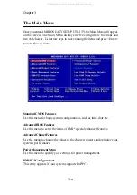
Page 44: ...CMOS changes and exit Getting Help After entering the Setup utility the first screen you see is the Main Menu MainMenu The main menu displays the setup categories the BIOS supplies You can use the arr...

Page 45: ...gisters and optimize your system s performance PowerManagementSetup Use this menu to specify your settings for power management PNP PCIConfigurations This entry appears if your system supports PnP PCI...

Page 46: ...isor Password Set User Password Use this menu to set User Password LoadHighPerformanceDefaults Use this menu to load the BIOS values for the best system performance but the system stability may be aff...

Page 47: ...llows you to set the system to the date that you want usually the current date The format is day month date year day Day of the week from Sun to Sat determined by BIOS Read only month The month from J...

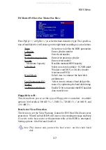
Page 48: ...disk performance Fast Programmed I O Select Auto to enhance hard disk perfor Modes mance by optimizing the hard disk timing 32 Bit Transfer Mode Enable 32 bit to maximize the IDE had disk data transf...

Page 49: ...k items Available options Enabled Disabled Full Screen Logo Show This item enables you to show the company logo on the bootup screen Set tings are Enabled Shows a still image logo on the full screen a...

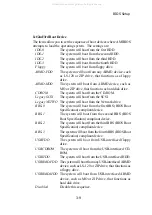
Page 50: ...gacy NETWO The system will boot from the Network drive BBS 0 The system will boot from the first BBS BIOS Boot Specification compliant device BBS 1 The system will boot from the second BBS BIOS Boot S...

Page 51: ...eys on the numeric keypad Setting options On Off FloppyDriveSwap Setting to Enabled will swap floppy drives A and B FloppyDriveSeek This setting causes the BIOS to search for floppy disk drives at boo...

Page 52: ...cess by the CPU The setting controls the internal cache also known as L1 or level 1 cache Setting to Enabled will speed up the system performance System BIOS Cacheable Selecting Enabled allows caching...

Page 53: ...ill expand available IRQs resources for the system Settings Enabled Disabled MPS Table Version This field allows you to select which MPS Multi Processor Specification version to be used for the operat...

Page 54: ...DRAMTimingControl Press Enter and the following sub menu appears Current Host Clock This item shows the current CPU frequency Note Change these settings only if you are familiar with the chipset All...

Page 55: ...eceiving it Settings 2 3 clocks 2 clocks increases the system performance the most while 3 clocks provides the most stable performance Row Precharge Time This item controls the number of cycles for Ro...

Page 56: ...al length of burst plus the starting address and allows internal address counter to properly generate the next memory location The bigger the size the faster the DRAM performance Settings 4 QW 8 QW SD...

Page 57: ...d Select Enabled only when the installed AGP card supports the function AGP Aperture Size This setting controls just how much system RAM can be allocated to AGP for video purposes The aperture is a po...

Page 58: ...transactions cycles so that transactions to and from the ISA bus are buffered and PCI bus can perform other transactions while the ISA transaction is underway Select Enabled to support compliance with...

Page 59: ...n choose to enter the Standby mode in S1 POS or S3 STR fashion through the setting of this field Options are S1 POS The S1 sleep mode is a low power state In this state no system context is lost CPU o...

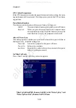
Page 60: ...M Setting to Enabled will activate an Advanced Power Management APM device to enhance Max Saving mode and stop CPU internal clock Settings Disabled Enabled Power SleepLED This item configures how the...

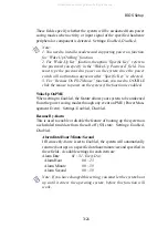
Page 61: ...e but if the button is pressed for more than four seconds the computer is turned off After AC Power Loss This setting specifies whether your system will reboot after a power failure or interrupt occur...

Page 62: ...if the function is enabled WakeUpOnPME When setting to Enabled the feature allows your system to be awakened from the power saving modes through any event on PME Power Man agement Event Settings Enabl...

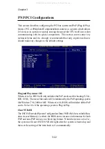
Page 63: ...set to Yes BIOS will only initialize the PnP cards used for booting VGA IDE SCSI The rest of the cards will be initialized by the PnP operating system like Windows 98 2000 or ME When set to No BIOS w...

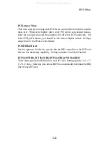
Page 64: ...o higher values Settings range from 32 to 248 at a 32 increment PCIIDEBusMaster Set this option to Enabled to specify that the IDE controller on the PCI local bus has bus mastering capability Settings...

Page 65: ...controller Serial Port 1 2 These items specify the base I O port addresses of the onboard Serial Port 1 COM A Serial Port 2 COM B Selecting Auto allows AMIBIOS to automati cally determine the correct...

Page 66: ...Port IRQ When OnBoard Parallel Port is set to Auto the item shows Auto indicat ing that BIOS determines the IRQ for the parallel port automatically Parallel Port DMA This feature needs to be configure...

Page 67: ...ntroller cards to connect a modem Settings Auto Enabled Disabled USB Controller This setting is used to enable disable the onboard USB ports Setting options 2 Ports 4 Ports 6 Ports USBLegacySupport Se...

Page 68: ...ed the system will automatically monitor the CPU fan during boot up If it detects that the CPU fan is not rotating the system will show an error message on the screen and halt the boot up process The...

Page 69: ...ce But if you are plagued by EMI setting to Enabled for EMI reduction Remember to disable Spread Spectrum if you are overclocking be cause even a slight jitter can introduce a temporary boost in clock...

Page 70: ...T recommended to change the default setting for long term usage DDRVoltage V Adjusting the DDR voltage can increase the DDR speed Any changes made to this setting may cause a stability issue so changi...

Page 71: ...password A message will show up confirming the password will be disabled Once the password is disabled the system will boot and you can enter Setup without entering any password When a password has b...

Page 72: ...t may lead to a stability issue When you select Load BIOS Setup Defaults a message as below appears Pressing Enter loads the default values that are factory settings for stable system performance The...

Page 73: ...f components and makes a more efficient design BIOS basic input output system On PCs an essential software that contains all the control code of input output inter face such as keyboard disk drives et...

Page 74: ...e semiconductor CMOS is a widely used type of semiconductor which features high speed and low power consumption PCs usually contain a small amount of battery powered CMOS memory to retain the date tim...

Page 75: ...ia infrared light waves This enables you to transfer data from one device to another without any cables LAN local area network A computer network that covers a relatively smaller area such as in a bui...

Page 76: ...erly connected and operating PS 2 Port A type of port developed by IBM for connecting a mouse or keyboard to a PC The PS 2 port supports a mini DIN plug containing just 6 pins Most modern PCs equipped...

Reviews: