background image

i

Version 1.0

G52-MA00485

MS-6552 (v1.X) M-ATX Mainboard

MSI

Summary of Contents for MS-6552

Page 1: ...i Version 1 0 G52 MA00485 MS 6552 v1 X M ATX Mainboard MSI...

Page 2: ...the equipment Notice 2 Shielded interface cables and A C powercord ifany must be used in order to comply with the emission limits VOIR LA NOTICE D INSTALLATION AVANT DE RACCORDER AU RESEAU Edition Nov...

Page 3: ...ure the equipment has not workwell oryou can not getit workaccording to User s Guide the equipment was dropped and damaged the equipment has obvious signs of breakage 12 Do not leave theis equipment i...

Page 4: ...tch Connector J8 2 23 Jumpers 2 24 Clear CMOS Jumper CLR_CMOS 2 24 BIOS Flash Jumper BIOS_WP 2 25 LAN Enable Disable Jumper JLAN1 2 25 Onboard Audio Codec Jumper JP3 2 26 Slots 2 27 AGP Accelerated Gr...

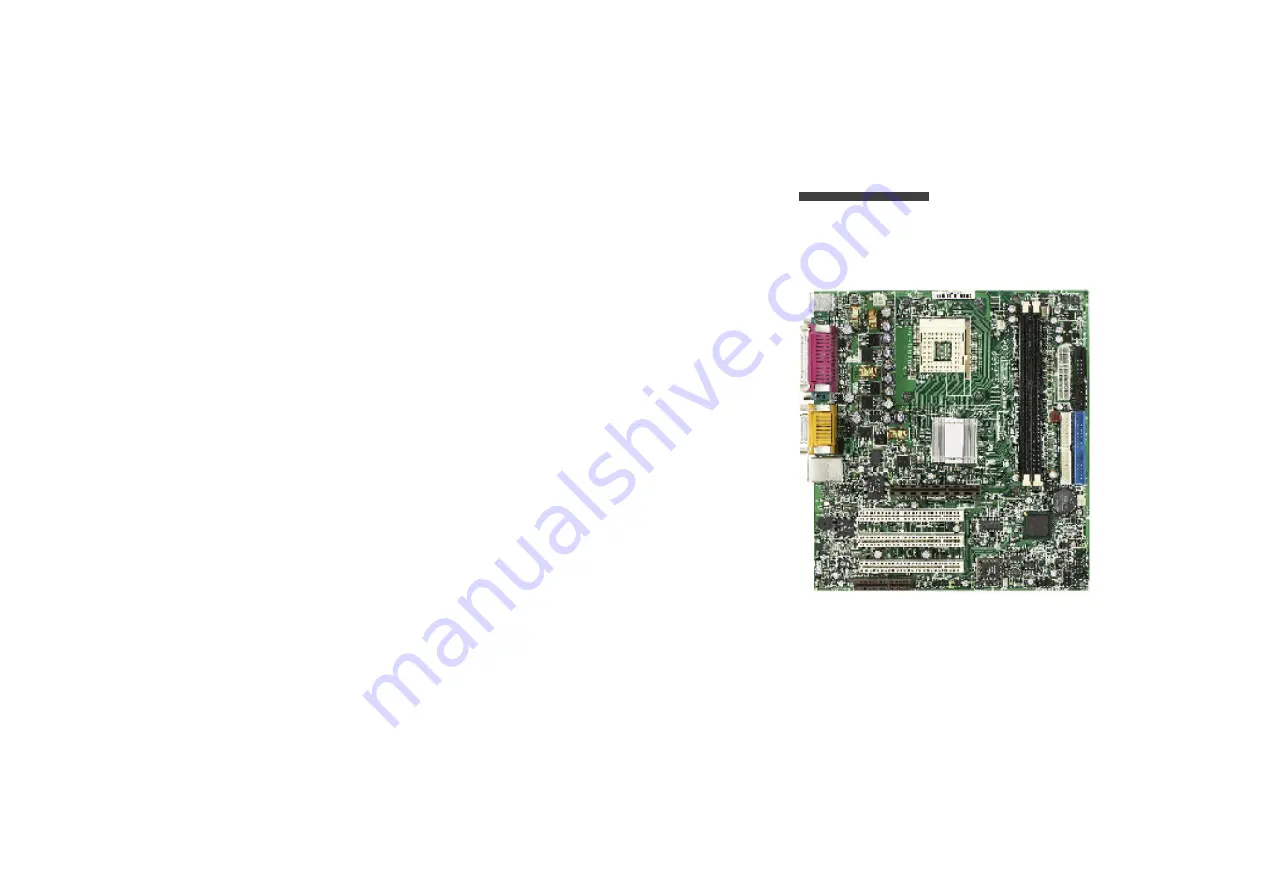
Page 5: ...de 1 5 1 Getting Started Thankyou foryourpurchase ofthe MS 6552M ATXmainboard Powered by the Intel Brookdale and ICH2 chipsets the MS 6552mainboard is designed to fit the advanced Intel Pentium 4 proc...

Page 6: ...Communication Network Riser slot On Board IDE An IDE controller on the ICH2 chipset provides IDE HDD CD ROM with Mainboard Specification PIO Bus Master and DMA33 100 operation modes Can connect up to...

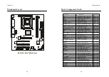
Page 7: ...See p 2 17 PANEL1 Case connector See p 2 18 F_AUDIO Front panel audio connector See p 2 19 USB2 Front USB connectors See p 2 20 PWR_SW1 Power switch connector See p 2 21 JGS1 Power saving switch conne...

Page 8: ...s chapter provides you with the information about hardware setup procedures While doing the installation be careful in holding the compo nents and follow the installation procedures For some component...

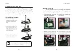
Page 9: ...stem always make sure the cooling fan can work properly to protect the CPU from overheating WARNING The mainboard supports Intel Pentium 4 processor in the 478 pin packag e The mainboard uses a CPU so...

Page 10: ...memory bandwidth makes DDR an ideal solution for high performance PC workstations and servers DDRDIMM Slots DDR 1 2 CPU Core Speed Derivation Procedure If CPU Clock 100MHz Core Bus ratio 14 then CPU...

Page 11: ...always make sure that all compo nents are installed properly to ensure that no damage will be caused ATX 12V Power Connector JPW1 This 12V power connector is used to provide power to the CPU DDR Modul...

Page 12: ...n assignments are as follows PS 2 Mouse 6 pinFemale 2 1 3 4 5 6 2 1 3 4 5 6 PIN SIGNAL DESCRIPTION 1 Mouse DA TA Mouse DA TA 2 NC No connection 3 GND Ground 4 VCC 5V 5 Mouse Clock Mouse clock 6 NC No...

Page 13: ...ta3 6 DA TA4 Data4 7 DA TA5 Data5 8 DA TA6 Data6 9 DA TA7 Data7 10 ACK Acknowledge 11 BUSY Busy 12 PE Paper End 13 SELECT Select 14 AUTO FEED Automatic Feed 15 ERR Error 16 INIT Initialize Printer 17...

Page 14: ...through the BIOS setup to use the IRfunction The IR2 is compliant to Intel Front Panel I O Connectivity Design Guide LAN Jack optional The mainboard provides one standard RJ 45 jack for connection to...

Page 15: ...or future BIOS and other devices These connec tors support the provided IDE hard disk cable IDE1 Primary IDE Connector The first hard drive should always be connected to IDE1 IDE1 can connect a Master...

Page 16: ...the positive and should be connected tothe 12V the blackwire is Ground and should be connected to GND If the mainboard has a System Hardware Monitor chipset on board you must use a specially designed...

Page 17: ...uide Case Connector PANEL1 The case connector block PANEL1 allows you to connect to the Power Switch Reset Switch Speaker Power LED and HDD LED on the case F_AUDIO Pin Description Pin Description 1 Ke...

Page 18: ...ector PWR_SW1 Attach a power switch to this connector Pressing the switch will turn on offthe system PWR_SW1 JGS1 Front USB Connectors USB2 Depending on the model you have purchased your mainboard cou...

Page 19: ...atus and show a warning messag e on the screen To clear the warning you must enter the BIOS utility and clear the record Power Saving LED Connector JGLED1 JGLED1 is connected to a power saving LED The...

Page 20: ...stem configuration With the CMOS RAM the system can automatically boot OS every time it is turned on That battery has long lifetime for atleast 5 years If you wantto clearthe system configuration use...

Page 21: ...d one CNR slot The AGP slot DOES NOT support 3 3V AGP card Use of 3 3V AGP card may cause damages to the mainboard To identify the spec of your AGP card refer to the documentation supplied with the AG...

Page 22: ...The CNR slot allows you to insert the CNR expansion cards CNR is a specially designed network audio or modem riser card for ATX family motherboards Its main processing is done through software and co...

Page 23: ...ored in a battery backed CMOS RAM so it retains the Setup information when the power is turned off TOPICS Entering Setup 3 2 The Main Menu 3 4 Standard CMOS Features 3 6 Advanced BIOS Features 3 9 Adv...

Page 24: ...Help screen Getting Help Power on the computer and the system will start POST Power On Self Test process When the message below appears on the screen press DEL key to enter Setup Hit DEL if you want t...

Page 25: ...xit Setup Save changes to CMOS and exit setup Exit Without Saving Abandon all changes and exit setup Standard CMOS Features Use this menu for basic system configurations such as time date etc Advanced...

Page 26: ...y BIOS Read only month The month from Jan through Dec date The date from 1 to 31 can be keyed by numeric function keys year The year can by adjusted by users Time This allows you to set the system tim...

Page 27: ...ng the item to Enabled BIOS will shorten or skip some check items during POST Settings Enabled and Disabled Fast Boot The option is the fastest boot to OS The hard disk drive will be the first boot de...

Page 28: ...sk operating system The settings are Floppy The system will boot from floppy drive LS120 The system will boot from LS 120 drive HDD 0 The system will boot from the first HDD SCSI The system will boot...

Page 29: ...2 and 2 5 clocks SDR 2 and 3 clocks Precharge Delay The field specifies the idle cycles before precharging an idle bank Settings Advanced Chipset Features use consult the vendor of your operating sys...

Page 30: ...ailable options are DDR Auto PC200 and PC266 SDR Auto PC100 and PC133 AGP Aperture Size MB The item is used to select the size of Accelerated Graphics Port AGP aperture Aperture is a portion of PCI me...

Page 31: ...enables IDE controller to use block mode Disabled allows the controller to use standard mode Floppy Controller The item is used to enable or disable the onboard Floppy controller Select Enabled when...

Page 32: ...re maintains all system context S3 STR The S3 sleep mode is a power down state in which power is supplied only to essential components such as main memory and wake capable devices and all Parallel Por...

Page 33: ...ement Resume By RTC Alarm The field is used to enable or disable the feature of booting up the system on a scheduled time date system context is saved to main memory The informa tion stored in memory...

Page 34: ...tion is set to Hot KEY youcan assign a hotkey combina tion in the field for the PS 2 keyboard to power on the system Settings Ctrl F1 through Ctrl F12 Power Again This item specifies whether your syst...

Page 35: ...ted to I O devices When an I O device needs to gain attention of the operating system it signals this by causing an IRQ to occur After receiving the signal when the operating system is ready the syste...

Page 36: ...MHz and 123 82 41 MHz Current SystemTemp Current CPUTemperature POWER SYSTEM CPU fan Vcore 3 3 V 5V 12V 12V VBAT V 5VSB V These items display the current status of all monitored hardware devices compo...

Page 37: ...gs of the setup menu User password Can only enter but do not have the right to change the settingsof the setup menu Set Supervisor User Password When you select this function a message as below willap...

Page 38: ...proves many placement of components and makes a more efficient design BIOS basic input output system On PCs an essential software that contains all the control code of input output inter face such as...

Page 39: ...r a line printer a name reserved by the MS DOS for upto three parallel printer ports LPT1 LPT2 and LPT3 It is frequently used by the OS to identify a printer Dynamic RAM DRAM Memory Technologies T ype...

Page 40: ...k drives etc to see if they are properly connected and operating PS 2 Port A type of port developed by IBM for connecting a mouse or keyboard to a PC The PS 2 port supports a mini DIN plug containing...

Reviews: