background image

1-3

Getting Started

On-Board Peripherals

h

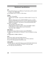
 On-Board Peripherals include:

- 1 floppy port supports 2 FDDs with 360K, 720K, 1.2M, 1.44M and

2.88Mbytes

- 2 serial ports (COM A + COM B)
- 1 parallel port supports SPP/EPP/ECP mode
- 1 IrDA connector for SIR/ASKIR/HPSIR
- 1 RJ-45 LAN jack
- 1 audio/game port
- 1 S-Bracket pin header
- 6 USB 2.0 ports (Rear * 4/ Front * 2)

Audio

h

 AC’97 link controller integrated in SiS

®

 963.

h

 RealTek ALC650 6-channel audio.

- Compliance with AC97 v2.2 Spec.
- Meets PC2001 audio performance requirement.
- Can support SPDIF Out via S-Bracket only.

LAN

h

 RealTek RTL8101L LAN controller.

BIOS

h

 The mainboard BIOS provides “Plug & Play” BIOS which detects the pe-

ripheral devices and expansion cards of the board automatically.

h

 The mainboard provides a Desktop Management Interface (DMI) function

which records your mainboard specifications.

Dimension

h

 ATX Form Factor: 30.5cm  x  24.5cm.

Mounting

h

 9 mounting holes.

Summary of Contents for MS-6585

Page 1: ...i MSI MS 6585 ATX Mainboard MICRO STAR INTERNATIONAL...

Page 2: ...manual may cause harmful interference to radio communications Operation of this equipment in a residential area is likely to cause harmful interference in which case the user will be required to corre...

Page 3: ...e right to make changes without notice Trademarks All trademarks are the properties of their respective owners Intel and Pentium are registered trademarks of Intel Corporation PS 2 and OS 2 are regist...

Page 4: ...ule 9 All cautions and warnings on the equipment should be noted 10 Never pour any liquid into the opening that could damage or cause electri cal shock 11 If any of the following situations arises get...

Page 5: ...rocedures for Socket 478 2 4 Installing the CPU Fan 2 5 Memory 2 7 Introduction to DDR SDRAM 2 7 DIMM Module Combination 2 8 Installing DDR Modules 2 8 Power Supply 2 9 ATX 20 Pin Power Connector CONN...

Page 6: ...3 Clear CMOS Jumper JBAT1 2 23 Slots 2 24 AGP Accelerated Graphics Port Slot 2 24 PCI Peripheral Component Interconnect Slots 2 24 CNR Communication Network Riser Slot 2 24 PCI Interrupt Request Routi...

Page 7: ...Set Supervisor User Password 3 28 Load Optimal Defaults 3 29 Appendix Using4 or6 ChannelAudioFunction A 1 Using the Back Panel only A 4 Testing the Connected Speakers A 7 Testing Each Speaker A 7 Pla...

Page 8: ...v2 XATX mainboard The MS 6585 is based on SiS648 and SiS963 chipsets for op timal system efficiency Designed to fit the advanced Intel Pentium 4 processors in the 478 pin package the MS 6585 de livers...

Page 9: ...963 371pinBGA Integrated Direct SoundAC97 audio Dual channel Ultra DMA33 66 100 133 master mode EIDE controller ACPI PC2001 compliant enhanced power management Integrated USB 2 0 controller MainMemory...

Page 10: ...AC 97 link controller integrated in SiS 963 hRealTekALC650 6 channel audio Compliance withAC97 v2 2 Spec Meets PC2001 audio performance requirement Can support SPDIF Out via S Bracket only LAN hRealTe...

Page 11: ...r Supply CPUFA SYSFA JIR1 JFP1 JFP2 JSP1 RealTek ALC650 Winbond W83697HF Realtek RTL8101L BIOS PCI Slot 5 PCI Slot 6 PCI Slot 4 PCI Slot 3 PCI Slot 2 PCI Slot 1 IDE 2 IDE 1 CNR JPW1 Top Parallel Port...

Page 12: ...Bracket Optional S Bracket is a bracket which provides a SPDIF jack Sony Philips Digital Interface for digital audio transmission The S Bracket offers a SPDIF connector for coaxial connection S Brack...

Page 13: ...dules and expansion cards as well as how to setup the jump ers on the mainboard Also it provides the instructions on connecting the peripheral devices such the mouse keyboard etc While doing the insta...

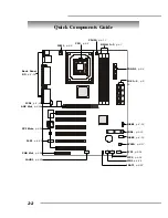
Page 14: ...1 3 p 2 7 CONN1 p 2 9 IDE1 2 p 2 16 JUSB1 p 2 19 FDD1 p 2 15 JUSB2 p 2 19 SYSFA p 2 17 JFP1 p 2 18 JFP2 p 2 18 JIR1 p 2 22 JBAT1 p 2 23 JAUD1 p 2 20 CNR Slot p 2 24 JSP1 p 2 21 PCI Slots p 2 24 AGP S...

Page 15: ...cking This motherboard is designed to support overclocking However please make sure your components are able to toler ate such abnormal setting while doing overclocking Any at tempt to operate beyond...

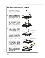
Page 16: ...e socket and can not be seen Please note that any violation of the correct installation pro cedures may cause permanent damages to your mainboard 5 Press the CPU down firmly into the socket and close...

Page 17: ...f the CPU Follow the instructions below to install the Heatsink Fan 2 Position the heatsink onto the reten tion mechanism 1 Locate the CPU and its retention mechanism on the motherboard 3 Mount the fa...

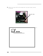
Page 18: ...2 6 MS 6585 ATX Mainboard 5 Connect the fan power cable from the mounted fan to the 3 pin fan power connector on the board fan power cable NOTES...

Page 19: ...t one DIMM module must be installed Memory DDR DIMM Slots DIMM 1 3 Introduction to DDR SDRAM DDR Double Data Rate SDRAM is similar to conventional SDRAM but doubles the rate by transferring data twice...

Page 20: ...ly fit in the right orientation 2 Insert the DIMM memory module vertically into the DIMM slot Then push it in until the golden finger on the memory module is deeply inserted in the socket 3 The plasti...

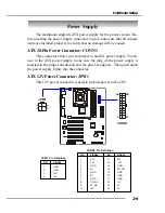
Page 21: ...ect to the ATX power supply make sure the plug of the power supply is inserted in the proper orientation and the pins are aligned Then push down the power supply firmly into the connector ATX 12VPower...

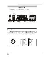
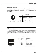
Page 22: ...2 mouse You can plug a PS 2 mouse directly into this connector The connector location and pin assignments are as follows PIN SIGNAL DESCRIPTION 1 Mouse DATA Mouse DATA 2 NC No connection 3 GND Ground...

Page 23: ...Definition PS 2 Keyboard 6 pin Female 2 1 3 4 5 6 USB Connectors The mainboard provides a UHCI Universal Host Controller Interface Universal Serial Bus root for attaching USB devices such as keyboard...

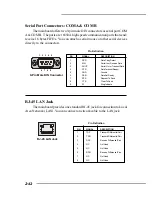
Page 24: ...erial Out or Transmit Data 4 DTR DataTerminal Ready 5 GND Ground 6 DSR DataSetReady 7 RTS Request To Send 8 CTS Clear To Send 9 RI Ring Indicate Pin Definition 9 Pin Male DIN Connector 1 2 3 4 5 6 7 8...

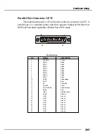
Page 25: ...mode 13 1 14 25 PIN SIGNAL DESCRIPTION 1 STROBE Strobe 2 DATA0 Data0 3 DATA1 Data1 4 DATA2 Data2 5 DATA3 Data3 6 DATA4 Data4 7 DATA5 Data5 8 DATA6 Data6 9 DATA7 Data7 10 ACK Acknowledge 1 1 BUSY Busy...

Page 26: ...Connectors Line Out Line In MIC Joystick Midi Connector You can connect a joystick or game pad to this connector MSIRemindsYou For advanced audio application RealTek ALC650 audio chip is provided to o...

Page 27: ...nect to FDD IDE HDD case modem LAN USB Ports IR module and CPU System Power Supply FAN Floppy Disk Drive Connector FDD1 The mainboard provides a standard floppy disk drive connector that supports 360K...

Page 28: ...00 133 controller that provides PIO mode 0 4 Bus Master and Ultra DMA33 66 100 133function Youcanconnectuptofourharddiskdrives CD ROM 120MB Floppy reserved for future BIOS and other devices These conn...

Page 29: ...lways take note that the red wire is the positive and should be connected to the 12V the black wire is Ground and should be connected to GND If the mainboard has a System Hardware Monitor chipset on b...

Page 30: ...h reference pull up 7 RST_SW_P Reset Switch high reference pull up 8 PWR_SW_N Power Switch low reference pull down to GND 9 RSVD_DNU Reserved Do not use JFP1 Pin Definition Power LED Speaker 1 2 7 8 J...

Page 31: ...B 2 0 technology increases data transfer rate up to a maximum throughput of 480Mbps which is 40 times faster than USB 1 1 and is ideal for connecting high speed USB interface peripherals such as USB H...

Page 32: ...gnal 2 AUD_GND Ground used by analog audio circuits 3 AUD_MIC_BIAS Microphone power 4 AUD_VCC Filtered 5V used by analog audio circuits 5 AUD_FPOUT_R Right channel audio signal to front panel 6 AUD_RE...

Page 33: ...y For more information on the S Bracket refer to Appendix Using 4 or 6 Channel Audio Function JSP1 1 11 2 12 PIN SIGNAL DESCRIPTION PIN SIGNAL DESCRIPTION 1 VCC5 VCC 5V 2 VDD3 VDD 3 3V 3 SPDFO S PDIF...

Page 34: ...ule You must configure the setting through the BIOS setup to use the IR function The JIR1 is compliant with Intel Front Panel I O Connectivity Design Guide JIR1 6 5 2 1 Pin Signal 1 NC 2 NC 3 VCC5 4 G...

Page 35: ...ery to keep the data of system configuration With the CMOS RAM the system can automatically boot OS every time it is turned on If you want to clear the system configuration use the JBAT1 Clear CMOS Ju...

Page 36: ...t Slots The PCI slots allow you to insert the expansion cards to meet your needs When adding or removing expansion cards make sure that you unplug the power supply first Meanwhile read the documentati...

Page 37: ...send interrupt signals to the microprocessor The PCI IRQ pins are typically connected to the PCI bus INT A INT D pins as follows Order 1 Order 2 Order 3 Order 4 PCI Slot 1 INTC INTD INTA INT B PCI Sl...

Page 38: ...tup pro gram and allows you to configure the system for optimum use You may need to run the Setup program when An error message appears on the screen during the system booting up and requests you to r...

Page 39: ...ility by pressing F11 When the same message as listed above appears on the screen press F11 to trigger the boot menu The POST messages might pass by too quickly for you to respond in time If so restar...

Page 40: ...the first screen you see is the Main Menu MainMenu The main menu displays the setup categories the BIOS supplies You can use the arrow keys to select the item The on line description for the selected...

Page 41: ...psetFeatures Use this menu to change the values in the chipset registers and optimize your system s performance PowerManagementFeatures Use this menu to specify your settings for power management Once...

Page 42: ...g for overall system status Frequency VoltageControl Use this menu to specify your settings for frequency voltage control Set Supervisor Password Use this menu to set Supervisor Password Set User Pass...

Page 43: ...alue you prefer System Time This allows you to set the system time that you want usually the current time The time format is hour minute second System Date This allows you to set the system to the dat...

Page 44: ...sector number MaximumCapacity Read the maximal HDD capacity LBA Mode Select Auto for a hard disk 512 MB un der Windows and DOS or Disabled un der Netware and UNIX Block Mode Select Auto to enhance the...

Page 45: ...tings are Enabled Shows a still image logo on the full screen at boot Disabled Shows the POST messages at boot Anti Virus Warning The item is to set the Virus Warning feature for IDE Hard Disk boot s...

Page 46: ...n compliant device BBS 2 The system will boot from the third BBS BIOS Boot Specification compliant device BBS 3 The system will boot from the fourth BBS BIOS Boot Specification compliant device USB FD...

Page 47: ...allow end users to use the arrow keys on the numeric keypad Setting options On Off FloppyDriveSeek This setting causes the BIOS to search for floppy disk drives at boot time When enabled the BIOS will...

Page 48: ...s how it handles writes to memory locations that are currently being held in cache The WriteBack cachelpolicy will produce the best performance APIC Select This field is used to enable or disable the...

Page 49: ...orwarded to the AGP without any translation The option allows the selection of an aperture size of 4MB 8MB 16MB 32MB 64MB 128MB and 256MB DRAMCAS Latency The field controls the CAS latency which deter...

Page 50: ...be required in certain system designs to support loose layouts or slower memory Setting options Safe Normal Fast Turbo Ultra MA 1T 2T Select This setting controls the SDRAM command rate Setting to Aut...

Page 51: ...ers the suspend sleep mode but if the button is pressed for more than four seconds the computer is turned off IPCAFunction This item is to activate the ACPI Advanced Configuration and Power Man agemen...

Page 52: ...ed allows BIOS to call VGA BIOS to initialize the VGA card when system wakes up resumes from S3 sleep state The system resume time is shortened when you disable the function but system will need an AG...

Page 53: ...power failure or interrupt occurs Available settings are Power Off Leaves the computer in the power off state Power On Reboots the computer Last State Restores the system to the previous status befor...

Page 54: ...abled Any Key Specific Key Password USBWakeup From S1 S3 This item allows the activity of the USB device to wake up the system from S1 S3 sleep state Settings Enabled Disabled Resume ByAlarm This is u...

Page 55: ...chnical items and it is strongly recommended that only experienced users should make any changes to the default settings Plug and PlayAware O S When set to Yes BIOS will only initialize the PnPcards u...

Page 56: ...Enter to enter the sub menu and the following screen appears IRQ 3 4 5 7 9 10 11 14 15 These items specify the bus where the specified IRQ line is used The settings determine ifAMIBIOS should remove...

Page 57: ...hat the system DMA Direct MemoryAccess channel is used The settings determine if AMIBIOS should remove a DMA from the available DMAs passed to devices that are configurable by the system BIOS The avai...

Page 58: ...e other controller cards to connect an audio device Settings Disabled and Auto MC 97Modem This item is used to enable or disable the onboard MC 97 Modem Codec 97 feature Selecting Auto allows the main...

Page 59: ...ardLAN This item is used to enable or disable the onboard LAN controllers Settings Enabled Disabled OnBoardPCI IDE This setting controls the onboard PCI IDE controllers Setting options Disabled Primia...

Page 60: ...I O port addresses of the onboard parallel port Selecting Auto allows AMIBIOS to automatically determine the correct base I O port address Settings Auto 378h 278h and Disabled Parallel Port Mode This...

Page 61: ...Port The field specifies the base I O port address for the onboard Midi Port Midi IRQ Select The item is used to select the IRQ line for onboard Midi port OnBoardGamePort This item is used to specify...

Page 62: ...r function is available only if there is hardware monitoring mecha nism onboard Vcore 3 3V 5 0V 12V 12V 5 0V Battery Voltage System CPU Fan Speed System CPUTemperature These items display the current...

Page 63: ...to the CPU FSB Clock preset DRAMFrequency This setting shows the current frequency of the installed DDR DRAM CPUMultipleFactory This item allows users to select the CPU multiplier value The default v...

Page 64: ...ouareoverclockingbecause even a slight jitter can introduce a temporary boost in clockspeed which may just cause your overclocked processor to lock up UnusedPCISlot DIMMClk This setting enables you to...

Page 65: ...When a password has been set you will be prompted to enter it every time you try to enter Setup This prevents an unauthorized person from chang ing any part of your system configuration Additionally w...

Page 66: ...Defaults are the values set by the mainboard manufacturer for optimized stable system performance When you select Load Optimal Defaults a message as below appears Pressing Enter loads the default BIO...

Page 67: ...hannel audio output including 2 Front 2 Rear 1 Center and 1 Subwoofer channel ALC650 allows the board to attach 4 or 6 speakers for better surround sound effect The section will tell you how to instal...

Page 68: ...DigitalAudio Output When any Multi Channel Audio Function mode is selected you may connect your speakers to the Coaxial SPDIF phonejack on the S Bracket to exprience digital surround sound effect S B...

Page 69: ...and have your speakers correctly con nected to the Back Panel Configuration in the Software Utility 1 Click the audio icon from the window tray at the lower right corner of the screen 2 Select a desi...

Page 70: ...utility connect your speakers to the correct phonejacks in accordance with the setting in software utility 2 Channel Mode forStereo SpeakerOutput Refer to the following diagram and caption for the fu...

Page 71: ...nnel Mode for 4 Speaker Output The audio jacks on the back panel always provide 2 channel analog audio output function however these audio jacks can be transformed to 4 or 6 channel analog audio jacks...

Page 72: ...selected 6 Channel Mode for 6 Speaker Output Refer to the following diagram and caption for the founction of each jack on the back panel when 6 Channel Mode is selected 1 2 3 MSIRemindsYou If the Cent...

Page 73: ...roperly you may need to test each connected speaker to make sure every speaker work properly If any speaker fails to sound then check whether the cable is inserted firmly to the connector or replace t...

Page 74: ...4 While you are testing the speakers in 6 Channel Mode if the sound com ing from the center speaker and subwoofer is swapped you should select Swap Center Subwoofer Output to readjust these two chann...

Page 75: ...yrics and leave melody for you to sing the song Note that this function applies only for 2 channel audio operation PlayingKaraOK 1 Click the audio icon from the window tray at the lower right corner o...

Reviews: