background image

A-2

 MS-6712 ATX Mainboard

Installing the Audio Driver

You need to install the driver for Realtek ALC650 chip to function properly
before you can get access to 4-/6-channel audio operations.  Follow the pro-
cedures described below to install the drivers for different operating systems.

Installation for Windows 98SE/ME/2000/XP

For Windows

®

 2000, you must install Windows

®

 2000 Service Pack2 or

later before installing the driver.

The following illustrations are based on Windows

®

 XP environment and

could look slightly different if you install the drivers in different operating
systems.

1.

Insert the companion CD into the CD-ROM drive.  The setup screen
will automatically appear.

2.

Click 

Avance ALC650 Sound Drivers

.

Click here

MSI Reminds You...

The 

AC97 Audio Configuration

software utility is under con-

tinuous update to enhance audio applications. Hence, the program
screens shown here in this appendix may be slightly different from
the latest software utility and shall be held for reference only.

Summary of Contents for MS-6712

Page 1: ...i KT4AV G52 M6712XJ MS 6712 v1 X ATX Mainboard...

Page 2: ...nce when the equip ment is operated in a commercial environment This equipment generates uses and can radiate radio frequency energy and if not installed and used in accor dance with the instruction m...

Page 3: ...demarks of International Business Machines Corporation Microsoft is a registered trademark of Microsoft Corporation Windows 98 2000 NT XPare registered trademarks of Microsoft Corporation NVIDIA the N...

Page 4: ...e equipment checked by a service personnel l The power cord or plug is damaged l Liquid has penetrated into the equipment l The equipment has been exposed to moisture l The equipment has not work well...

Page 5: ...nnel Optional 1 8 LiveBIOS LiveDriver 1 10 CPUThermal Protection 1 11 S Bracket Optional 1 11 Chapter2 HardwareSetup 2 1 Quick Components Guide 2 2 Central Processing Unit CPU 2 3 CPU Core Speed Deriv...

Page 6: ...CFAN1 SFAN1 2 17 Front Panel Connectors JFP1 JFP2 2 18 Front Panel Audio Connector JAUD1 2 19 Front USB Connector JUSB1 2 20 D Bracket 2Connector JLED1 2 21 S Bracket Connector JSP3 2 22 IrDA Infrare...

Page 7: ...3 18 PNP PCI Configurations 3 22 Integrated Peripherals 3 24 PC Health Status 3 27 Frequency Voltage Control 3 28 Set Supervisor User Password 3 30 Load High Performance BIOS Setup Defaults 3 31 Appen...

Page 8: ...1 X ATX mainboard is based on VIA Apollo KT400A North Bridge VT8235 South Bridge chipset for optimal system efficiency Designed to fit the ad vanced AMD Athlon Athlon XPor Duron processors the MS 6712...

Page 9: ...er mode EIDE controller ACPI PC2001 compliant enhanced power management Integrated USB 2 0 controller MainMemory Supports six memorybanks using three 184 pin DDR DIMMs Supports upto3GBPC1600 2100 2700...

Page 10: ...nnel audio LAN VIA VT6103LANcontroller BIOS The mainboard BIOS provides Plug Play BIOS which detects the pe ripheral devices and expansion cards of the board automatically The mainboard provides a Des...

Page 11: ...er Supply CFAN1 JBAT1 JIR1 SFAN1 JUSB1 JFP1 JFP2 JSP3 JCI1 Codec Winbond W83697HF VIA VT6103 BIOS PCI Slot 5 PCI Slot 6 PCI Slot 4 PCI Slot 3 PCI Slot 2 PCI Slot 1 IDE 1 IDE 2 CNR Top Parallel Port Bo...

Page 12: ...dialog box will appear You can specify how often the system will automatically search for the BIOS drivers version or change the LAN settings right from the dialog box You can right click the MSI Liv...

Page 13: ...f there are any problems or failures D Bracket 2 sup ports both USB 1 1 2 0 spec D Bracket 2 for mainboard with bluetooth connector 1 port 1 2 3 4 D Bracket 2 Description System Power ON The D LED wil...

Page 14: ...ze the video adapter BIOS Sign On This will start showing information about logo processor brand name etc Testing Base and Extended Memory Testing base memory from 240K to 640K and extended memory abo...

Page 15: ...audio codec s software utility Otherwise the 6 channel audio function will not work properly For information on how to select 6 channel mode in the audio software utility refer to Appendix Using 4 or...

Page 16: ...information about MSI DVD you can refer to the online help coming with the application To enter the online help 1 Click on the icon at the bottom right corner of the control panel 2 The following wind...

Page 17: ...and the follow ing screen will appear Five buttons are placed on the leftmost pane of the screen Click the desired button to start the update process z z z z z Live BIOS Updates the BIOS online z z z...

Page 18: ...et Optional S Bracket is a bracket which provides 2 SPDIF jacks for digital audio transmission and 2 analog Line Out connectors for additional 4 channel ana log audio output With the S Bracket your sy...

Page 19: ...nsion cards as well as how to setup the jump ers on the mainboard Also it provides the instructions on con necting the peripheral devices such as the mouse keyboard etc While doing the installation be...

Page 20: ...P3 p 2 22 DDR DIMMs p 2 7 CPU p 2 3 CFAN1 p 2 17 FDD1 p 2 15 SFAN1 p 2 17 JLED1 p 2 21 IDE1 IDE2 p 2 16 JFP1 JFP2 p 2 18 JUSB1 p 2 20 JAUD1 p 2 19 JIR1 p 2 24 JCI1 p 2 24 JCD1 p 2 25 JWR1 p 2 9 AGP Sl...

Page 21: ...stems Maintaining the proper thermal environment is key to reliable operation As such the processor must be maintained in the specified thermal requirements AMD Athlon Duron Athlon XP processor with a...

Page 22: ...the socket and can not be seen Please note that any violation of the correct installation procedures may cause permanent damages to your mainboard 5 Press the CPU down firmly into the socket and close...

Page 23: ...ns will guide you through the heat sink installation procedures Please consult your agent for the proper CPU cooler set 1 Position your CPU cooler set onto the CPU 2 Use one end of the clip to hook th...

Page 24: ...ng will seriously damage the CPU and system al ways make sure the cooling fan can work properly to protect the CPU from overheating Replacing the CPU While replacing the CPU always turn off the ATX po...

Page 25: ...se note that the mainboard supports only one DDR400 DIMM DDR DIMM Slots DDR 1 3 Introduction to DDR SDRAM DDR Double Data Rate SDRAM is similar to conventional SDRAM but doubles the rate by transferri...

Page 26: ...n the right orientation 2 Insert the DIMM memory module vertically into the DIMM slot Then push it in until the golden finger on the memory module is deeply in serted in the socket 3 The plastic clip...

Page 27: ...nector JWR1 This connector allows you to connect to an ATX power supply To connect to the ATX power supply make sure the plug of the power supply is inserted in the proper orientation and the pins are...

Page 28: ...a PS 2 mouse You can plug a PS 2 mouse directly into this connector The connector location and pin assignments are as follows PIN SIGNAL DESCRIPTION 1 Mouse DATA Mouse DATA 2 NC No connection 3 GND Gr...

Page 29: ...in Definition PS 2 Keyboard 6 pin Female 2 1 3 4 5 6 USB Connectors The mainboard provides a UHCI Universal Host Controller Interface Universal Serial Bus root for attaching USB devices such as keyboa...

Page 30: ...CP mode 13 1 14 25 PIN SIGNAL DESCRIPTION 1 STROBE Strobe 2 DATA0 Data0 3 DATA1 Data1 4 DATA2 Data2 5 DATA3 Data3 6 DATA4 Data4 7 DATA5 Data5 8 DATA6 Data6 9 DATA7 Data7 10 ACK Acknowledge 11 BUSY Bus...

Page 31: ...microphones MSI Reminds You For advanced audio application RealTek ALC650 audio chip is provided as an option to offer support for 6 channel audio operation and can turn rear audio connectors from 2...

Page 32: ...SOUT Serial Out or Transmit Data 4 DTR Data Terminal Ready 5 GND Ground 6 DSR Data Set Ready 7 RTS Request To Send 8 CTS Clear To Send 9 RI Ring Indicate Pin Definition 9 Pin Male DIN Connector 1 2 3...

Page 33: ...to connect to FDD IDE HDD case modem LAN USB Ports IR module and CPU System FAN Floppy Disk Drive Connector FDD1 The mainboard provides a standard floppy disk drive connector that supports 360K 720K 1...

Page 34: ...E1 Primary IDE Connector The first hard drive should always be connected to IDE1 IDE1 can connect a Master and a Slave drive You must configure second hard drive to Slave mode by setting the jumper ac...

Page 35: ...12V the black wire is Ground and should be connected to GND If the mainboard has a System Hardware Monitor chipset on board you must use a specially designed fan with speed sensor to take advantage o...

Page 36: ...MSG LED pull up 3 HD_LED_N Hard disk active LED 4 FP PWR SLP MSG LED pull up 5 RST_SW_N Reset Switch low reference pull down to GND 6 PWR_SW_P Power Switch high reference pull up 7 RST_SW_P Reset Swi...

Page 37: ...circuits 5 AUD_FPOUT_R Right channel audio signal to front panel 6 AUD_RET_R Right channel audio signal return from front panel 7 HP_ON Reserved for future use to control headphone amplifier 8 KEY No...

Page 38: ...10 USBOC JUSB1 Pin Definition MSI Reminds You The USB 2 0 technology is downward compatible with USB 1 1 spec To use the USB 2 0 ports you have to install the USB 2 0 driver which is supplied by Micr...

Page 39: ...ough 16 various combinations of LED signals For definitions of 16 signal combinations please refer to D Bracket 2 Optional in Chapter 1 Pin Signal 1 DBG1 high for green color 2 DBR1 high for red color...

Page 40: ...o optical SPDIF jack you need to re move the plug from the jack first The two SPDIF jacks support SPDIF out put only For more information on the S Bracket refer to Appendix Using 4 or 6 Channel Audio...

Page 41: ...2 23 Hardware Setup Optional S Bracket SPDIFJack optical Analog Line Out Jacks Connect to JSP3 SPDIF Jack coaxial CEN SUB RL RR...

Page 42: ...Panel I O Connectivity Design Guide Pin Signal 1 NC 2 NC 3 VCC5 4 GND 5 IRTX 6 IRRX JIR1 Pin Definition Chassis Intrusion Switch Connector JCI1 This connector is connected to a 2 pin chassis switch I...

Page 43: ...2 25 Hardware Setup CD In Connector JCD1 The connector is for CD ROM audio connector JCD1 GND R L...

Page 44: ...tery to keep the data of system configuration With the CMOS RAM the system can automatically boot OS every time it is turned on If you want to clear the system configuration use the JBAT1 Clear CMOS J...

Page 45: ...eeds When adding or removing expansion cards make sure that you unplug the power supply first Meanwhile read the documentation for the expansion card to make any necessary hardware or software setting...

Page 46: ...interrupt signals to the microprocessor The PCI IRQ pins are typically connected to the PCI bus INT A INT D pins as follows Order 1 Order 2 Order 3 Order 4 PCI Slot 1 INT A INT B INT C INT D PCI Slot...

Page 47: ...m and allows you to configure the system for optimum use You may need to run the Setup program when An error message appears on the screen during the system booting up and requests you to run SETUP Yo...

Page 48: ...ility by pressing F11 When the same message as listed above appears on the screen press F11 to trigger the boot menu The POST messages might pass by too quickly for you to respond in time If so restar...

Page 49: ...ormance settings for all devices and the system while High Performance defaults provide the best system performance but may affect the system stability Move to the previous item Move to the next item...

Page 50: ...the values in the chipset registers and optimize your system s performance Power Management Features Use this menu to specify your settings for power management PNP PCI Configurations This entry appe...

Page 51: ...word Use this menu to set Supervisor Password Set User Password Use this menu to set User Password Load High Performance Defaults Use this menu to load the BIOS values for the best system performance...

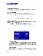
Page 52: ...t the system time that you want usually the current time The time format is hour minute second System Date This allows you to set the system to the date that you want usually the current date The form...

Page 53: ...I O Select Auto to enhance hard disk perfor Modes mance by optimizing the hard disk timing 32 Bit Transfer Mode Enable 32 bit to maximize the IDE hard disk data transfer rate Floppy Drive A B This it...

Page 54: ...w the company logo on the bootup screen Set tings are Enabled Shows a still image logo on the full screen at boot Disabled Shows the POST messages at boot Boot Sequency Press Enter to enter the sub me...

Page 55: ...BIOS Boot Specification compliant device BBS 3 The system will boot from the 4th BBS BIOS Boot Specification compliant device BBS 4 The system will boot from the 5th BBS BIOS Boot Specification compli...

Page 56: ...is to set the Num Lock status when the system is powered on Set ting to On will turn on the Num Lock key when the system is powered on Setting to Off will allow end users to use the arrow keys on the...

Page 57: ...ata the system transfers the requested data from the main DRAM into cache memory for even faster access by the CPU The setting controls the internal cache also known as L1 or level 1 cache Setting to...

Page 58: ...to select which MPS Multi Processor Specification version to be used for the operating system You need to select the MPS ver sion supported by your operating system To find out which version to use co...

Page 59: ...k This item shows the current CPU frequency Configure SDRAM Timing by Selects whether DRAM timing is controlled by the SPD Serial Presence Detect EEPROM on the DRAM module Setting to SPD enables Advan...

Page 60: ...item controls the number of cycles for Row Address Strobe RAS to be allowed to precharge If insufficient time is allowed for the RAS to accumulate its charge before DRAM refresh refresh may be in com...

Page 61: ...llows internal address counter to properly generate the next memory location The bigger the size the faster the DRAM performance Settings 4 QW 8 QW SDRAM 1T Command This setting controls the SDRAM com...

Page 62: ...ed AGP Aperture Size This setting controls just how much system RAM can be allocated to AGP for video purposes The aperture is a portion of the PCI memory address range dedicated to graphics memory ad...

Page 63: ...ffer to support delayed transactions cycles so that transactions to and from the ISA bus are buffered and PCI bus can perform other transactions while the ISA transaction is underway Select Enabled to...

Page 64: ...d hardware main tains all system context S3 STR The S3 sleep mode is a lower power state where the in formation of system configuration and open applications files is saved to main memory that remains...

Page 65: ...ow the system uses power LED on the case to indicate the sleep suspend state Available options are Single LED The power LED turns off to indicate the sleep suspend state Dual LED The power LED changes...

Page 66: ...l reboot after a power failure or interrupt occurs Available settings are Power Off Leaves the computer in the power off state Power On Leaves the computer in the power on state Last State Restores th...

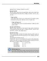
Page 67: ...system from S3 Suspend to RAM sleep state Settings Disabled double click Left button double click Right button Resume By Alarm This is used to enable or disable the feature of booting up the system o...

Page 68: ...Plug and Play Aware O S When set to Yes BIOS will only initialize the PnP cards used for booting VGA IDE SCSI The rest of the cards will be initialized by the PnP operat ing system like Windows 98 200...

Page 69: ...to 248 at a 32 increment PCI IDE BusMaster Set this option to Enabled to specify that the IDE controller on the PCI local bus has bus mastering capability Settings options Disabled Enabled Primary Gr...

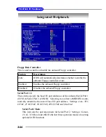
Page 70: ...ally determine the correct base I O port address Settings Auto 3F8 COM1 2F8 COM2 3E8 COM3 2E8 COM4 and Disabled Serial Port2 Mode This item sets the operation mode for Serial Port 2 Settings Normal 1...

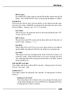
Page 71: ...1 7 1 9 Port IRQ When OnBoard Parallel Port is set to Auto the item shows Auto indicat ing that BIOS determines the IRQ for the parallel port automatically Port DMA This feature needs to be configure...

Page 72: ...ble the controller if you want to use other controller cards to connect a modem Settings Auto Disabled OnChip USB Controller This setting is used to enable disable the onboard USB ports Setting option...

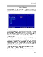
Page 73: ...Detection When enabled the system will automatically monitor the CPU fan during boot up If it detects that the CPU fan is not rotating the system will show an error message on the screen and halt the...

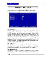
Page 74: ...plagued by EMI select one of the options for EMI reduction Remember to disable Spread Spectrum if you are overclocking because even a slight jitter can introduce a temporary boost in clockspeed which...

Page 75: ...speed Any changes made to this setting may cause a stability issue so changing the DDR voltage for long term purpose is NOT recommended Termination Vol V The settings are used to adjust the terminatio...

Page 76: ...hen a password has been set you will be prompted to enter it every time you try to enter Setup This prevents an unauthorized person from changing any part of your system configuration Additionally whe...

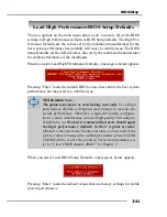
Page 77: ...stem performance but may lead to a stability issue When you select Load BIOS Setup Defaults a message as below appears Pressing Enter loads the default values that are factory settings for stable syst...

Page 78: ...audio output including 2 Front 2 Rear 1 Center and 1 Subwoofer channel ALC650 allows the board to attach 4 or 6 speakers for better surround sound effect The section will tell you how to install and...

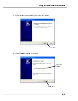
Page 79: ...before installing the driver The following illustrations are based on Windows XP environment and could look slightly different if you install the drivers in different operating systems 1 Insert the co...

Page 80: ...A 3 Using 4 or 6 Channel Audio Function 3 Click Next to start installing files into the system 4 Click Finish to restart the system Click here Click here Select this option...

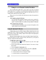
Page 81: ...to the audio connectors on the back panel Using the Optional S Bracket S Bracket integrates the SPDIF Sony Philips Digital Interface and analog LINE OUT connectors together With this optional accesso...

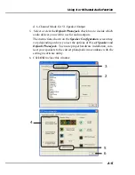
Page 82: ...you wish to use for audio outputs The instructions shown on the Speaker Configuration screen may vary depending on how you set the options of No of Speaker and Default Phonejack To ensure proper hard...

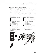
Page 83: ...ead of the Line Out connector on the S Bracket Refer to the following diagram and caption for the function of each phonejack on the back panel when 2 Channel mode is selected 2 MIC 3 Line In 1 Line Ou...

Page 84: ...racket when 4 Channel mode is selected 2 MIC 3 Line In 1 Front Speaker Out Front channels 4 Optical SPDIF jack 5 Coaxial SPDIF jack 6 Line Out Reserved for Center and Subwoofer channel but it is not f...

Page 85: ...l SPDIF jack 6 Line Out Center and Subwoofer channels 7 Line Out Rear channels Select Default Phonejack Deselect Default Phonejack 2 Center Subwoofer Speaker Out Center and Subwoofer channels 3 Rear S...

Page 86: ...PDIF jack 2 Coaxial SPDIF jack 1 2 MSI Reminds You Some commonly used audio output for mats midi wav etc may not be able to be output from the SPDIF jacks of the S Bracket To convert these audio forma...

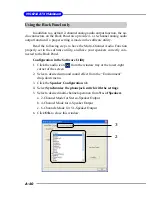
Page 87: ...ave your speakers correctly con nected to the Back Panel Configuration in the Software Utility 1 Click the audio icon from the window tray at the lower right corner of the screen 2 Select a desired su...

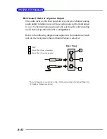
Page 88: ...re utility connect your speakers to the correct phonejacks in accordance with the setting in software utility 2 Channel Mode for Stereo Speaker Output Refer to the following diagram and caption for th...

Page 89: ...ys provide 2 channel analog audio output function however these audio jacks can be transformed to 4 or 6 channel analog audio jacks by selecting the corresponding multi channel operation from No of Sp...

Page 90: ...the founction of each jack on the back panel when 6 Channel Mode is selected MSI Reminds You If the Center and Subwoofer speaker exchange their audio chan nels when you play video or music on the com...

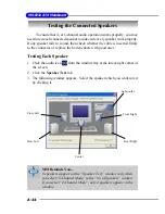
Page 91: ...ly you may need to test each connected speaker to make sure every speaker work properly If any speaker fails to sound then check whether the cable is inserted firmly to the connector or replace the ba...

Page 92: ...Function 4 While you are testing the speakers in 6 Channel Mode if the sound com ing from the center speaker and subwoofer is swapped you should select Swap Center Subwoofer Output to readjust these t...

Page 93: ...nd leave melody for you to sing the song Note that this function applies only for 2 channel audio operation Playing KaraOK 1 Click the audio icon from the window tray at the lower right corner of the...

Page 94: ...AWARD R 2nd 5th digit refers to the model number 6th 7th digit refers to the customer as MS all standard customers V1 0 refers to the BIOS version 091096 refers to the date this BIOS is released Q Doe...

Page 95: ...wrong BIOS or some other reasons Suggestions 1 try the BIOS boot recovery feature as described in http www msi com tw html support bios note boot htm 2 try to clear the CMOS If problem still persists...

Page 96: ...roduct firmware refer to http www msi com tw pro gram support driver dvr spt_dvr_list php part 4 Q Where can I find MSI developed software such as Fuzzy Logic or PC Alert A Refer to http www msi com t...

Page 97: ...ort manual mnu spt_mnu_list php kind 7 Q Where can I find the drivers A Please refer to the following suggestions 1 Try the BIOS boot recov ery feature as described in http www msi com tw support bios...

Page 98: ...your board under the socket478 area If in case you cannot find your board then refer to http www msi com tw program support cpu_support cpu spt_cpu_list php kind 1 CHIP Archives ID 4 find your board a...

Page 99: ...efer to http www msi com tw html contact contact htm For more information of each MSI subsidiary company please move your mouse arrow to the symbol Q Mysystemcannotbootup whatshallIdo A There are many...

Page 100: ...the problem Disable all on board device like audio RAID or others apply see if it is due to resource conflict Move the PCI card to different PCI slots Update the card BIOS or drivers Update the mothe...

Page 101: ...unused frequency band of 2 45 GHz that is available globally with some variation of bandwidth in different countries In addition to data up to three voice channels are available Each device has a uni...

Page 102: ...y circuits for transmitting and receiv ing data a PC chipset provides the electronic interfaces between all subsystems Clock Cycle Clock cycle or tick is the smallest unit of time recognized by a devi...

Page 103: ...mass storage devices of up to 8 4 gigabytes whereas the old standard was limited to 528 MB Because of its lower cost enhanced EIDE has replaced SCSI in many areas There are four EIDE modes defined The...

Page 104: ...rrupt Request Line IRQs are hardware lines over which devices can send interrupt signals to the microprocessor When you add a new device to a PC you sometimes need to set its IRQ number by setting a D...

Page 105: ...s LPT1 LPT2 and LPT3 It is frequently used by the OS to identify a printer Overclocking Overclocking is resetting your computer so that the microprocessor runs faster than the manufacturer specified s...

Page 106: ...vices to computers SCSI interfaces provide for faster data transmission rates up to 80 megabytes per second than standard serial and parallel ports In addition you can attach many devices to a single...

Page 107: ...K Micron 256M MT46V16M8 5TB ES OK OK OK OK OK MS 6712 V 1 0A XCOPYx2 VCD Speedy 3D Mark2001SE v330 Demo Mode Suspender S3 Mode Windows Reboot Windows Shutdown PC3200 DDR400 x 2 Play 12hr Looping 12hr...

Page 108: ...B 5 W942508CH 5 OK OK Winbond 256M Kingston KVR400X64C25 256 W942508BH 5 OK OK SEC 256M M368L3223DTM CC4 K4H560838D TCC4 OK OK CORSAIR 256M CMX256A 3200C2 XMS3200V1 1 OK OK CORSAIR 256M CMX256A 3500C2...

Page 109: ...fineon 128M HYS64D16301GU 5 B HYB25D256160BT 5 OK OK MICRON 256M MT16VDDT3264AG 403B4 US MT46V16M8TG 5 ES B OK OK Winbond 256M W9425GCDB 5 W942508CH 5 OK OK Winbond 256M Kingston KVR400X64C25 256 W942...

Reviews: