background image

3-2

 MS-6743G M-ATX Mainboard

Entering Setup

Power on the computer and the system will start POST (Power On Self Test)
process. When the message below appears on the screen, press <DEL> key to
enter Setup.

Press DEL to enter SETUP

If the message disappears before you respond and you still wish to enter Setup,
restart the system by turning it OFF and On or pressing the RESET button.
You may also restart the system by simultaneously pressing <Ctrl>, <Alt>,
and <Delete> keys.

Control Keys

<

Move to the previous item 

<

Move to the next item 

<

Move to the item in the left hand 

<

Move to the item in the right hand 

<Enter> Select 

the 

item 

<Esc> 

Jumps to the Exit menu or returns to the main menu from a submenu 

<+/PU> 

Increase the numeric value or make changes 

<-/PD> 

Decrease the numeric value or make changes 

<F1> 

General help, only for Status Page Setup Menu and Option Page 

Setup Menu 

<F5> 

Restore the previous CMOS value from CMOS, only for Option Page 

Setup Menu 

<F6> 

Load the default CMOS value from Fail-Safe default table, only for 

Option Page Setup Menu 

<F7> 

Load Optimized defaults 

<F10> 

Save all the CMOS changes and exit 

Summary of Contents for MS-6743G

Page 1: ...i Version 1 2 G52 M6743X5 865GVM MS 6743G v1 X Micro ATX Mainboard...

Page 2: ...th the instruction manual may cause harmful interference to radio communications Operation of this equipment in a residential area is likely to cause harmful interference in which case the user will b...

Page 3: ...of International Business Machines Corporation Microsoft is a registered trademark of Microsoft Corporation Windows 98 2000 NT XP are registered trademarks of Microsoft Corporation NVIDIA the NVIDIA...

Page 4: ...module 9 All cautions and warnings on the equipment should be noted 10 Never pour any liquid into the opening that could damage or cause electri cal shock 11 If any of the following situations arises...

Page 5: ...6 PC Alert 4 1 7 Chapter2 HardwareSetup 2 1 Quick Components Guide 2 2 Central Processing Unit CPU 2 3 CPU Core Speed Derivation Procedure 2 3 CPU Installation Procedures for Socket 478 2 4 Installing...

Page 6: ...ional 2 17 Front Panel Connector JFP1 2 17 Serial ATA Connectors SATA1 SATA2 2 18 Chassis Intrusion Switch Connector JCI1 2 18 Front Panel Audio Connector JAUD1 2 19 Front USB Connectors JUSB1 JUSB2 2...

Page 7: ...Status 3 28 Frequency Voltage Control 3 29 Load High Performance BIOS Setup Defaults 3 31 Set Supervisor User Password 3 32 Appendix Using2 4 or6 ChannelAudioFunction A 1 Installing C Media Driver A 2...

Page 8: ...the MS 6743G v1 X M ATX mainboard The MS 6743 is based on Intel Springdale GV Intel ICH5 chipsets for optimal system efficiency Designed to fit the advanced Intel Pentium 4 processor in the 478 pin pa...

Page 9: ...r SMBus 2 0 support 2 serial ATA Host Controllers Integrated LAN controller MainMemory h Supports four 64 bit wide DDR data channels h Available bandwidth up to 3 2GB s DDR 400 for single channel mode...

Page 10: ...t SPDIF Out via bracket only On BoardLAN h Intel82562EZ Integrated 10 100 Ethernet MAC and PHY in one chip Supports 10Mb s and 100Mb s auto negotiation operation Compliant with PCI v2 2 and LAN on Mot...

Page 11: ...DDR 2 T mouse B keyboard T Line Out B Mic Line In M JSP1 JAUD1 JCD1 Codec BATT BIOS Winbond 83627HF AW ICH5 Intel Springdale 865GV IDE 1 IDE 2 FDD1 PCI Slot 1 PCI Slot 2 PCI Slot 3 CPU_FAN SYSTEM_FAN...

Page 12: ...e 3 icon and the following screen will appear Five buttons are placed on the left column of the screen Click the desired button to start the update process Live BIOS Updates the BIOS online Live Drive...

Page 13: ...box will appear You can specify how often the system will automatically search for the BIOS drivers version or change the LAN settings right from the dialog box You can right click the MSI Live Monito...

Page 14: ...rogram main screen will be immediately shown on the screen with the abnormal item highlighted in red This will continue to be shown until the condition returns to the normal status Users can use the A...

Page 15: ...own below with information about the CPU and chipset Right click the mouse to select the skin you want to switch to Cute MSIRemindsYou 1 The new feature COOLER XP will work only if your mainboard supp...

Page 16: ...les and expansion cards as well as how to setup the jump ers on the mainboard Also it provides the instructions on con necting the peripheral devices such as the mouse keyboard etc While doing the ins...

Page 17: ...16 JPW1 p 2 9 CPU p 2 3 Back Panel I O p 2 10 CPU_FAN1 p 2 15 FDD1 p 2 15 STAT2 SATA1 p 2 18 JCI1 p 2 18 JSPD1 p 2 17 JFP1 p 2 17 DDR DIMMs p 2 7 ATX1 p 2 9 JAUD1 p 2 19 JUSB1 p 2 19 JBAT1 p 2 20 JUSB...

Page 18: ...100MHz x 14 1 4 GHz The mainboard supports Intel Pentium 4 Celeron Northwood Prescott processor in the 478 pin package The mainboard uses a CPU socket called PGA478 for easy CPU installation When you...

Page 19: ...socket and can not be seen Please note that any violation of the correct installation procedures may cause permanent damages to your mainboard 5 Press the CPU down firmly into the socket and close the...

Page 20: ...the CPU Follow the instructions below to install the Heatsink Fan 2 Position the heatsink onto the reten tion mechanism 1 Locate the CPU and its retention mechanism on the motherboard 3 Mount the fan...

Page 21: ...om grounded outlet first to ensure the safety of CPU Overclocking This motherboard is designed to support overclocking However please make sure your components are able to toler ate such abnormal sett...

Page 22: ...oduction to DDR SDRAM DDR Double Data Rate SDRAM is similar to conventional SDRAM but doubles the rate by transferring data twice per cycle It uses 2 5 volts as opposed to 3 3 volts used in SDR SDRAM...

Page 23: ...r of module The mod ule will only fit in the right orientation 2 Insert the DIMM memory module vertically into the DIMM slot Then push it in until the golden finger on the memory module is deeply in s...

Page 24: ...ect to the ATX power supply make sure the plug of the power supply is inserted in the proper orientation and the pins are aligned Then push down the power supply firmly into the connector ATX 12V Powe...

Page 25: ...a PS 2 keyboard directly into this connector Mouse Connector The mainboard provides a standard PS 2 mouse mini DIN connector for attaching a PS 2 mouse You can plug a PS 2 mouse directly into this co...

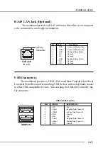
Page 26: ...ive Data Channel 0 4 GND Ground 5 VCC 5V 6 Data 1 Negative Data Channel 1 7 Data 1 Positive Data Channel 1 8 GND Ground USB Port Description USB Ports 1 2 3 4 5 6 7 8 RJ 45 LAN Jack Optional The mainb...

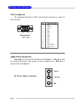
Page 27: ...N C 5 GND 6 GND 7 GND 8 GND 9 5V 10 GND 11 N C 12 SDA 13 Horizontal Sync 14 Vertical Sync 15 SCL VGA Connector DB 15 pin 1 5 11 15 Audio Port Connectors Line Out is a connector for Speakers or Headph...

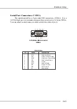
Page 28: ...s FIFOs You can attach a serial mouse or other serial device directly to it PIN SIGNAL DESCRIPTION 1 DCD Data Carry Detect 2 SIN Serial In or Receive Data 3 SOUT Serial Out or Transmit Data 4 DTR Data...

Page 29: ...ECP mode 13 1 14 25 PIN SIGNAL DESCRIPTION 1 STROBE Strobe 2 DATA0 Data0 3 DATA1 Data1 4 DATA2 Data2 5 DATA3 Data3 6 DATA4 Data4 7 DATA5 Data5 8 DATA6 Data6 9 DATA7 Data7 10 ACK Acknowledge 11 BUSY Bu...

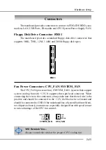
Page 30: ...rocessor fan SYSTEM_FAN1 system fan support system cooling fan with 12V It supports three pin head connector When connecting the wire to the connectors always take note that the red wire is the positi...

Page 31: ...drive should always be connected to IDE1 IDE1 can connect a Master and a Slave drive You must configure second hard drive to Slave mode by setting the jumper accordingly IDE2 Secondary IDE Connector...

Page 32: ...panel switches and LEDs JFP1 is compliant with Intel Front Panel I O Connectivity Design Guide PIN SIGNAL DESCRIPTION 1 HD_LED_P Hard disk LED pull up 2 FP PWR SLP MSG LED pull up 3 HD_LED_N Hard dis...

Page 33: ...k devices Optional Serial ATA cable Serial ATA Connectors SATA1 SATA2 The mainboard has dual high speed Serial ATA interface connectors SATA1 SATA2 Each supports 1st generation serial ATA data rates o...

Page 34: ...l return from front panel JAUD1 Pin Definition JAUD1 1 2 9 10 MSI Reminds You If you don t want to connect to the front audio header pins 5 6 9 10 have to be jumpered in order to have signal output di...

Page 35: ...Avoid clearing the CMOS while the system is on it will damage the mainboard Clear CMOS Jumper JBAT1 There is a CMOS RAM on board that has a power supply from external battery to keep the data of syste...

Page 36: ...expansion card such as jumpers switches or BIOS configuration PCI Interrupt Request Routing The IRQ abbreviation of interrupt request line and pronounced I R Q are hardware lines over which devices c...

Page 37: ...etup program and allows you to configure the system for optimum use You may need to run the Setup program when An error message appears on the screen during the system booting up and requests you to r...

Page 38: ...t and Delete keys Control Keys Move to the previous item Move to the next item Move to the item in the left hand Move to the item in the right hand Enter Select the item Esc Jumps to the Exit menu or...

Page 39: ...keys to highlight the field and press Enter to call up the sub menu Then you can use the con trol keys to enter values and move from field to field within a sub menu If you want to return to the main...

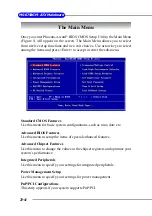
Page 40: ...performance Integrated Peripherals Use this menu to specify your settings for integrated peripherals Power Management Setup Use this menu to specify your settings for power management PnP PCI Configur...

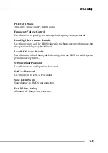
Page 41: ...lues for the best system performance but the system stability may be affected Load BIOS Setup Defaults Use this menu to load factory default settings into the BIOS for stable system performance operat...

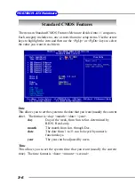
Page 42: ...c date The date from 1 to 31 can be keyed by numeric function keys year The year can be adjusted by users Time This allows you to set the system time that you want usually the current time The time fo...

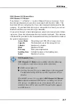
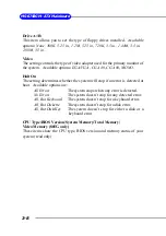
Page 43: ...or the system manufacturer Access Mode The settings are CHS LBA Large Auto Capacity The formatted size of the storage device Cylinder Number of cylinders Head Number of heads Precomp Write precompensa...

Page 44: ...ines whether the system will stop if an error is detected at boot Available options are All Errors The system stops when any error is detected No Errors The system doesn t stop for any detected error...

Page 45: ...ite data into this area is made BIOS will display a warning message on screen and beep Settings Disabled and Enabled Hyper Threading Technology The processor uses Hyper Threading technology to increas...

Page 46: ...stem fails to boot from the 1st 2nd 3rd boot device Swap Floppy Drive Setting to Enabled will swap floppy drives A and B Boot Up NumLock LED This setting is to set the Num Lock status when the system...

Page 47: ...h the keys are accelerated Settings 6 8 10 12 15 20 24 and 30 Typematic Delay Msec This item allows you to select the delay between when the key was first pressed and when the acceleration begins Sett...

Page 48: ...S M A R T This allows you to activate the S M A R T Self Monitoring Analysis Re porting Technology capability for the hard disks S M A R T is a utility that monitors your disk status to predict hard d...

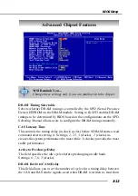
Page 49: ...ers to configure the DRAM timings manually CAS Latency Time This controls the timing delay in clock cycles before SDRAM starts a read command after receiving it Settings 2 2 5 3 clocks 2 clocks in cre...

Page 50: ...ny program writes to this memory area a system error may result Setting options Enabled Disabled Video BIOS Cacheable Selecting Enabled allows caching of the video BIOS ROM at C0000h to C7FFFh resulti...

Page 51: ...ttings PCI Slot Onboard AGP On Chip VGA Setting On Chip VGA This setting determines whether the system RAM can be allocated to on chip video controller for video purposes When setting to Enabled up to...

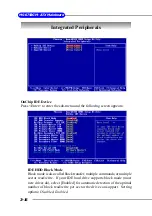
Page 52: ...en appears IDE HDD Block Mode Block mode is also called block transfer multiple commands or multiple sector read write If your IDE hard drive supports block mode most new drives do select Enabled for...

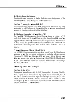
Page 53: ...best mode for each device The settings are Auto Mode 0 Mode 1 Mode 2 Mode 3 Mode 4 Primary Secondary Master Slave UDMA Ultra DMA 33 implementation is possible only if your IDE hard drive supports it a...

Page 54: ...y Slave Compatible Mode with Serial ATA Port 1 set to Sec ondary Slave Primary Master Compatible Mode with only Serial ATA Enabled and Port 1 set to Primary Master Secondary Master Compatible Mode wit...

Page 55: ...ons Enabled Disabled AC97 Audio Auto allows the motherboard s BIOS to detect whether you re using any audio device If so the onboard audio controller will be enabled If not the onboard audio controlle...

Page 56: ...floppy disk controller FDD in stalled on the system board and you wish to use it If you install add on FDC or the system has no floppy drive select Disabled in this field The settings are Enabled and...

Page 57: ...unction the following message will be displayed on the screen EPP Mode Select At this time either EPP 1 7 spec or EPP 1 9 spec can be chosen ECP Mode Use DMA The ECP mode has to use the DMA channel so...

Page 58: ...ll system context S3 STR The S3 sleep mode is a lower power state where the in formation of system configuration and open applications files is saved to main memory that remains powered while most oth...

Page 59: ...for power management Min Saving Minimum Power Management Suspend Mode 1 Hour Max Saving Maximum Power Management Suspend Mode 1 Min User Define Allows end users to configure each mode separately Vide...

Page 60: ...n Settings are Power Off The power button functions as a normal power on off button Suspend When you press the power button the computer en ters the suspend sleep mode but if the button is pressed for...

Page 61: ...obal Timer Events Primary Secondary IDE 0 1 FDD COM LPT Port PCI PIRQ A D The global timer is the hardware timer that counts down to the power saving modes If the monitoring of the listed hardware per...

Page 62: ...only initialize the PnP cards used for booting VGA IDE SCSI The rest of the cards will be initialized by the PnP oper ating system like Windows 98 When set to No BIOS will initialize all the PnP card...

Page 63: ...register in the PCI device configuration space is the VGA Palette Snoop bit 0 is disabled For example if there are two VGA devices in the computer one PCI and one ISA and the The setting must be set t...

Page 64: ...ed later Setting options Enabled Reset Disabled Current System Temp Current CPU Temperature Current CPU Fan Speed Current System Fan Speed Vcore V VTT V 3 3V 5V 12V 12V 5V VBAT V 5VSB V These items di...

Page 65: ...hen the motherboard s clock generator pulses the extreme values spikes of the pulses creates EMI Electromagnetic Interference The Spread Spec trum function reduces the EMI generated by modulating the...

Page 66: ...e by entering a number between maximum 200 MHz to minimum 100 MHz AGP PCI Clock Control This item is used to control the synchronous setting between CPU frequency and AGP PCI clock When set to Synchro...

Page 67: ...fically for optimal performance of the mainboard The BIOS Setup Defaults are the default values set by the BIOS vendor for stable system performance When you select Load High Performance Defaults a me...

Page 68: ...ord just press Enter when you are prompted to enter the password A message will show up confirming the password will be disabled Once the password is disabled the system will boot and you can enter Se...

Page 69: ...Xear 3DTM technology a value add PC audio total solution In addtion C Media designs a Universal Driver Architecture UDA driver which has a flexible interface so that it can be applied to different pl...

Page 70: ...ation h Users can adjust the best field dynamically adapted to different appliances and sound sources h A new multi channel listening mode is provided Earphone plus You can use open aired earphones in...

Page 71: ...sound and also use this program to adjust your virtual speakers before playing 3D audio applications like gaming 7 Demo Program Multi channel Music Multi channel Music Demo Program has three 5 1 chann...

Page 72: ...can attach the speakers for 4 6 channel audio output Always connect the speakers to the LINE OUT connectors Different connector configurations for 2 4 6 channel operations are listed below Hardware Co...

Page 73: ...en Then the C Media 3D Audio Configuration will appear Click on the Speaker Output tab to configure the audio Software Configuration h Bass Enhancement You may enable the Bass Enhancement option to en...

Page 74: ...bass signal is by ring of it as the figure showed below However some speakers have opposite definition Please use this option to solve the possible trouble In the left side check the radio button nex...

Page 75: ...nal to S PDIF digital output in real time This is useful to transfer the analog audio from one device to the S PDIF interface of another such as the external decoder or the amplifier of Home Theater h...

Page 76: ...to digital format you have to click Select Source button and select one analog source in the Select Source window Actually the selected item synchronizes with the recording panel of Microsoft Choose...

Page 77: ...gher volume level of digital audio you can enable Loudness AGC It provides extra 3dB to 12dB gain to all channels The driver has also been designed with a sophisticated auto gain control minimizing th...

Page 78: ...elect the microphone input you are going to use But if your system does not support 2 microphone inputs then you won t see two items Thereal panel microphone jack is sometimes shared by center subwoof...

Page 79: ...Click on the Xear 3D tab and the following screen appears C MediaUDAdrivernowsupportsXear3D 5 1VirtualSPEAKERSHIRFTER and sound effects Just click the left button in Xear 3D tab and the new friendly f...

Page 80: ...27 environ ment effects 3 environment sizes and 10 band pre set equalizer You may choose the provided environ ments by clicking the buttons Bathroom Concert Hall Sewer Pipe and Music Pub or use the d...

Page 81: ...also click each speaker to test your connection configuration Moreover it can help you to adjust your virtual speakers for multi channel audio applications like DVD 2 DemoProgram This part contains mu...

Page 82: ...g The default setting for SPEAKER SHIFTER is OFF thus you have to click on it to make it ON in which all the speakers are available to adjust YoumaymoveFront Left Front Right Rear Left Rear Rightvirtu...

Page 83: ...e the Sound Effect tab in the Xear 3D Advanced Program Demo Program will not be installed automatically Please click C Media Sound Drivers again for the complete installation of C Media applications P...

Page 84: ...M ATX Mainboard The Xear3D Sound Play3D Demo program is showed as follows Five built in Sound Sources Six Envornment Effects which will synchronize with the Environment setting on Sound Effect part Fi...

Page 85: ...re playing 3D audio applications like gaming When clicking each of the Moving Path icons Drag Path Horizontal Circle Vertical Circle Z Path and Random Curve a rea moving ball indicates the 3D source s...

Page 86: ...ors on the Back Panel also provide 4 or 6 Channel analog audio out put function if a proper setting is made in the software utility Read the following steps to have the Multi Channel Audio Function pr...

Page 87: ...r 6 channel analog audio jacks by selecting the corresponding multi channel op eration from No of Speakers Refer to the following diagram and caption for the founction of each jack on the back panel w...

Page 88: ...enter and Subwoofer speaker are swapped when you play video or music on the computer a converter may be required to exchange center and subwoofer audio signals The converter can be purchased from a sp...

Reviews: