background image

3-20

 MS-7060 Micro ATX Mainboard

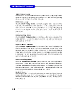
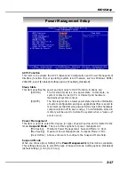
Resume By Alarm

The field is used to enable or disable the function of Resume By Alarm.  Setting
options: [Disabled], [Enabled].

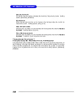
Month Alarm

When Resume By Alarm is set to Enabled, the field specifies the month for

Resume By Alarm

.  Setting options: [NA], [1-12].

Date of Month Alarm

When Resume By Alarm is set to Enabled, the field specifies the date for 

Resume

By Alarm

.  Setting options: [0]

~

[31].

Time (hh:mm:ss) Alarm

When Resume By Alarm is set to Enabled, the field specifies the time for 

Resume

By Alarm

.  Format is <hour><minute><second>.

** Reload Global Timer Events **
Primary/Secondary IDE, FDD/COM/LPT Ports, PCI PIRQ [A-D]#

The global timer is the hardware timer that counts down to the power saving modes.  If
the monitoring of the listed hardware peripherals or components is enabled, the activity
of the specified peripherals or components will awaken the system or reload the
original count of global timer when they are accessed. Setting options: [Disabled],
[Enabled]

Summary of Contents for MS-7060

Page 1: ...i G52 M7060X4 661FM2 Series MS 7060 v1 X Micro ATX Mainboard...

Page 2: ...talled and used in accor dance with the instruction manual may cause harmful interference to radio communications Operation of this equipment in a residential area is likely to cause harmful interfere...

Page 3: ...is a registered trademark of Microsoft Corporation Windows 98 2000 NT XP are registered trademarks of Microsoft Corporation NVIDIA the NVIDIA logo DualNet and nForce are registered trademarks or trade...

Page 4: ...r module 9 All cautions and warnings on the equipment should be noted 10 Never pour any liquid into the opening that could damage or cause electrical shock 11 If any of the following situations arises...

Page 5: ...Speed Derivation Procedure 2 3 Memory Speed CPU FSB Support Matrix 2 3 CPU Installation Procedures for Socket 478 2 4 Installing the CPU Fan 2 5 Memory 2 7 Introduction to DDR SDRAM 2 7 DDR Module Com...

Page 6: ...9 Front Panel Connectors JFP1 JFP2 2 19 CD In Connector JCD1 2 20 Front Panel Audio Connector JAUD1 2 20 Front USB Connectors JUSB1 JUSB2 2 21 SPDIF Connector JSP1 2 21 Jumpers 2 22 Clear CMOS Jumper...

Page 7: ...ID Basics 4 2 Performance hints and recommend setting 4 2 RAID 0 Striping array 4 3 RAID 1 Mirror array 4 3 JBOD Spanning array 4 3 System BIOS Setup 4 4 BIOS Configuration 4 5 Starting BIOS Utility 4...

Page 8: ...Installing the Audio Driver A 2 Installation for Windows 98SE ME 2000 XP A 2 Using 4 or 6 Channel Audio Function A 4 Using the Back Panel A 4 Testing the Connected Speakers A 9 Testing Each Speaker A...

Page 9: ...1 X Micro ATX mainboard The 661FM2 series is based on SiS 661FX SiS 964 chipsets for optimal system efficiency Designed to fit the advanced Intel Pentium 4 processor in the 478 pin package the 661FM2...

Page 10: ...us with 1GHz bandwidth h SiS 964 Supports Dual IDE ATA 100 133 Integrated audio controller with AC97 interface Supports HyperTransport Technology Advanced power management and PC2001 compliance Serial...

Page 11: ...CD In pinheader Audio h AC97 link controller integrated in SiS 964 h 5 1 channels Realtek ALC655 S W audio codec Comply with AC97 2 3 Spec Meets PC2001 audio performance requirement Can support SPDIF...

Page 12: ...FAN1 CPU FAN1 JBAT1 BIOS PCI Slot 3 PCI Slot 2 PCI Slot 1 IDE 1 IDE 2 JCOM1 Top Parallel Port Bottom COM port VGA port Top mouse Bottom keyboard Top LAN Jack Bottom USB ports Top 1394 port Optional Bo...

Page 13: ...ules and expansion cards as well as how to setup the jumpers on the mainboard It also provides the instructions on connecting the peripheral devices such as the mouse keyboard etc While doing the inst...

Page 14: ...p 2 15 JUSB1 p 2 21 PCI Slots p 2 23 IDE1 IDE2 p 2 16 JBAT1 p 2 22 JPW1 p 2 9 JAUD1 p 2 20 CONN1 p 2 9 JCD1 p 2 20 JFP2 p 2 19 CPUFAN1 p 2 15 DDR DIMMs p 2 7 JSP1 p 2 21 AGP Slot p 2 23 SYSFAN1 p 2 15...

Page 15: ...d the heat sink and cooling fan contact your dealer to purchase and install them before turning on the computer For the latest information about CPU please visit http www msi com tw program products m...

Page 16: ...the pins should be completely embedded into the socket and can not be seen Please note that any violation of the correct instal lation procedures may cause per manent damages to your mainboard 5 Pres...

Page 17: ...f the CPU Follow the instructions below to install the Heatsink Fan 2 Position the heatsink onto the retention mechanism 1 Locate the CPU and its retention mechanism on the motherboard 3 Mount the fan...

Page 18: ...2 6 MS 7060 Micro ATX Mainboard 5 Connect the fan power cable from the mounted fan to the 3 pin fan power connector on the board fan power cable NOTES...

Page 19: ...ated supporting memory modules please visit http www msi com tw program products mainboard mbd pro_mbd_trp_list php DDR DIMM Slots DDR 1 2 Introduction to DDR SDRAM DDR Double Data Rate SDRAM is simil...

Page 20: ...nter of module The module will only fit in the right orientation 2 Insert the DIMM memory module vertically into the DIMM slot Then push it in until the golden finger on the memory module is deeply in...

Page 21: ...the power supply is inserted in the proper orientation and the pins are aligned Then push down the power supply firmly into the connector ATX 12V Power Connector JPW1 This 12V power connector is used...

Page 22: ...2 mouse You can plug a PS 2 mouse directly into this connector The connector location and pin assignments are as follows PIN SIGNAL DESCRIPTION 1 MouseDATA MouseDATA 2 NC Noconnection 3 GND Ground 4 V...

Page 23: ...for attaching USB devices such as keyboard mouse or other USB compatible devices You can plug the USB device directly into the connector USB Ports 1 2 3 4 5 6 7 8 PIN SIGNAL DESCRIPTION 1 VCC 5V 2 Da...

Page 24: ...Ring Indicate Pin Definition VGA Connector The mainboard provides a DB 15 pin female connector to connect a VGA monitor VGA Connector DB 15 pin 1 5 11 15 Pin Signal Description 1 RED 2 GREEN 3 BLUE 4...

Page 25: ...audio For more information on 6 channel audio operation please refer to Appendix Using 4 or 6 Channel Audio Function Pin Definition PIN SIGNAL DESCRIPTION 1 TDP Transmit Differential Pair 2 TDN Trans...

Page 26: ...rt ECP mode 13 1 14 25 PIN SIGNAL DESCRIPTION 1 STROBE Strobe 2 DATA0 Data0 3 DATA1 Data1 4 DATA2 Data2 5 DATA3 Data3 6 DATA4 Data4 7 DATA5 Data5 8 DATA6 Data6 9 DATA7 Data7 10 ACK Acknowledge 1 1 BUS...

Page 27: ...essor fan and SYSFAN1 system fan support system cooling fan with 12V They support three pin head connector When connecting the wire to the connectors always take note that the red wire is the positive...

Page 28: ...e provided IDE hard disk cable IDE1 Primary IDE Connector The first hard drive should always be connected to IDE1 IDE1 can connect a Master and a Slave drive You must configure second hard drive to Sl...

Page 29: ...ATA 1 0 specifications Each Serial ATA connector can connect to 1 hard disk drive PIN SIGNAL PIN SIGNAL 1 GND 2 TXP 3 TXN 4 GND 5 RXN 6 RXP 7 GND Pin Definition Connect to SATA1 or SATA2 Take out the...

Page 30: ...inal Ready 5 GND Ground 6 DSR DataSetReady 7 RTS Request To Send 8 CTS Clear To Send 9 RI Ring Indicate Pin Definition Serial Port Connector JCOM1 The mainboard offers one serial port JCOM1 It is 1655...

Page 31: ...SW_P Power Switch high reference pull up 7 RST_SW_P Reset Switch high reference pull up 8 PWR_SW_N Power Switch low reference pull down to GND 9 RSVD_DNU Reserved Do not use JFP1 Pin Definition Chassi...

Page 32: ...not function PIN SIGNAL DESCRIPTION 1 AUD_MIC Front panel microphone input signal 2 AUD_GND Ground used by analog audio circuits 3 AUD_MIC_BIAS Microphonepower 4 AUD_VCC Filtered 5V used by analog aud...

Page 33: ...1 JUSB1 JUSB2 USB 2 0 Intel spec 1 9 2 10 PIN SIGNAL PIN SIGNAL 1 VCC 2 VCC 3 USB0 4 USB1 5 USB0 6 USB1 7 GND 8 GND 9 Key 10 USBOC JUSB1 JUSB2 Pin Definition 1 3 Front USB Connectors JUSB1 JUSB2 The m...

Page 34: ...battery to keep the data of system configuration With the CMOS RAM the system can automatically boot OS every time it is turned on If you want to clear the system configuration use the JBAT1 Clear CM...

Page 35: ...When adding or removing expansion cards make sure that you unplug the power supply first Meanwhile read the documentation for the expansion card to make any necessary hardware or software settings for...

Page 36: ...OS category described in this chapter are under continuous update for better system performance Therefore the description may be slightly different from the latest BIOS and should be held for referenc...

Page 37: ...RESET button You may also restart the system by simultaneously pressing Ctrl Alt and Delete keys Control Keys Move to the previous item Move to the next item Move to the item in the left hand Enter S...

Page 38: ...keys to highlight the field and press Enter to call up the sub menu Then you can use the control keys to enter values and move from field to field within a sub menu If you want to return to the main...

Page 39: ...ings for integrated peripherals Power Management Setup Use this menu to specify your settings for power management PNP PCI Configurations This entry appears if your system supports PnP PCI PC Health S...

Page 40: ...oad Optimized Defaults Use this menu to load factory default settings into the BIOS for stable system perfor mance operations Set Supervisor Password Use this menu to set Supervisor Password Set User...

Page 41: ...at determined by BIOS Read only month The month from Jan through Dec date The date from 1 to 31 can be keyed by numeric function keys year The year can be adjusted by users Time The time format is hou...

Page 42: ...f floppy drives installed Setting options None 360K 5 25 in 1 2M 5 25 in 720K 3 5 in 1 44M 3 5 in 2 88M 3 5 in Video The setting controls the type of video adapter used for the primary monitor of the...

Page 43: ...tem is to set the Virus Warning feature for IDE Hard Disk boot sector protection If the function is Enabled and any attempt to write data into this area is made BIOS will display a warning message on...

Page 44: ...rs Sec After Typematic Rate Setting is Enabled this item allows you to set the rate characters second at which the keys are accelerated Setting options 6 8 10 12 15 20 24 30 Typematic Delay Msec This...

Page 45: ...d is used to Enabled or Disabled the APIC Advanced Programmable Interrupt Controller Due to compliance to PC2001 design guide the system is able to run in APIC mode Enabling APIC mode will expand avai...

Page 46: ...nce Mode This setting particularly provided by SiS gives the proper suggestion for user to set timing The Timings programmed into this register are dependent on the sys tem design Setting options Enab...

Page 47: ...Control is set to Manual this field is adjustable This setting controls the number of cycles for Row Address Strobe RAS to be allowed to precharge If insufficient time is allowed for the RAS to accum...

Page 48: ...AGP Fast Write Support This option Enabled or Disabled the AGP Fast Write feature The Fast Write technology allows the CPU to write directly to the graphics card without passing anything through the...

Page 49: ...interface supports Modes 0 through 4 provide successively increased performance In Auto mode the system automatically determines the best mode for each device Setting options Auto Mode 0 Mode 1 Mode...

Page 50: ...n the operating system that does not support or does not have any USB driver installed such as DOS and SCO Unix SiS AC97 Audio Auto allows the mainboard to detect whether an audio device is used If an...

Page 51: ...he onboard parallel port Setting options 378 IRQ7 278 IRQ5 3BC IRQ7 Disabled Parallel Port Mode This item selects the operating mode for the parallel port Normal SPP EPP ECP or ECP EPP SPP Standard Pa...

Page 52: ...ion and open applications files is saved to main memory that remains powered while most other hardware components turn off to save energy The information stored in memory will be used to restore the s...

Page 53: ...abled 1 15 Mins Power Button Function This feature allows users to configure the Power Button function Setting options Power Off The power button functions as a normal power on off button Suspend When...

Page 54: ...ed only Setting options Enabled Disabled Wake Up On PME USB Wakeup From S3 These fields specify whether the system will be awakened from power saving modes when activity or input signal of the specifi...

Page 55: ...arm Setting options 0 31 Time hh mm ss Alarm When Resume By Alarm is set to Enabled the field specifies the time for Resume By Alarm Format is hour minute second Reload Global Timer Events Primary Sec...

Page 56: ...Access Memory is where the BIOS stores resource information for both PNP and non PNP devices in a bit string format When the item is set to Enabled the system will reset ESCD NVRAM right after the sys...

Page 57: ...nt buses can handle data from the CPU on each set of palette registers on every video device Bit 5 of the command register in the PCI device configuration space is the VGA Palette Snoop bit 0 is disab...

Page 58: ...he current temperature reaches to the minimum threshold the set temperature minus the tolerance value the fan will slow down to keep the temperature stable Setting options Min 0 o C Max 15 o C 0o C me...

Page 59: ...rum When the motherboard s clock generator pulses the extreme values spikes of the pulses creates EMI Electromagnetic Interference The Spread Spectrum function reduces the EMI generated by modulating...

Page 60: ...r specifically for optimal performance of the mainboard The Fail Safe Defaults are the default values set by the BIOS vendor for stable system performance When you select Load Fail Safe Defaults a mes...

Page 61: ...y password When a password has been set you will be prompted to enter it every time you try to enter Setup This prevents an unauthorized person from changing any part of your system configuration Addi...

Page 62: ...Large LBA support for drives over 137 GB 3 Data handling optimizations including tagged command queuing elevator seek and packet chain command Serial Ultra ATA RAID function supports striping RAID 0...

Page 63: ...lost if even any one drive in the RAID set crashes 3 RAID 1 Also known as Mirroring Two hard drives are required The goal of RAID 0 is to ensure data security Data is written to two or more drives sy...

Page 64: ...ror system HDD Population Rules for RAID 1 Striping Ultra ATA Master Ultra ATA Slave Serial ATA Master 1 Serial ATA Master 2 X X V V V Selected X Unselected NOTE Storage Capacity the capacity of the s...

Page 65: ...still wish to enter Setup restart the system by turning it OFF and On or pressing the RESET button You may also restart the system by simultaneously pressing Ctrl Alt and Delete keys Once you enter BI...

Page 66: ...r you can select N to ignore this message d Found a new HD Do you want to rebuild RAID 1 Y Occurs when the controller has broken Raid 1 and single HDD existing simultaneously and the location of singl...

Page 67: ...y the SiS964 Utility Main Menu 3 Press R to display the RAID setup menu below This is the fastest and easiest method to create your first array The A and D key will appear randomly in the different co...

Page 68: ...4 7 Introduction to SiS964 SATA RAID b No available disk existing but have RAID existing c Available disks and RAID existing simultaneously...

Page 69: ...Available disk is not enough to create RAID Create a RAID 0 Stripe Array for performance To create an array for best performance please follow these steps 1 Press A to start creating a RAID array 2 P...

Page 70: ...1 If you select 1 Auto Create you can create a RAID 0 array faster and easier The Blocksize will be selected by its default value 64K The result after auto creating will be shown on step 6 Besides yo...

Page 71: ...n the disk you wanted the RAID Type will be changed from Single to RAID 0 And the disk you select first will be the SOURCE disk 6 Next you will see a message Split the SOURCE Disk x data to RAID disks...

Page 72: ...uction to SiS964 SATA RAID 7 Starting splitting action the following frame will be shown 8 After all steps finished press Q until escape the setup menu and RAID 0 array will be shown on the top of the...

Page 73: ...o save changes 10 Once the array has been created you will need to FDISK and FORMAT the array as if it were a new single hard drive Create a RAID 1 Mirror Array for performance To create a Mirror arra...

Page 74: ...1 array faster and easier The result after creating will be shown on step 5 Besides you also can select 2 Manual Create see following steps 4 Use to select disk and press Enter to select disk Q to exi...

Page 75: ...see a message Duplicate the SOURCE Disk x data to RAID disks Press N and Enter to create RAID 1 array only or press Y and Enter to duplicate the data from source disk to mirror disk 6 Starting duplic...

Page 76: ...will be shown on the top of the main frame 8 Press Q until exit this BIOS utility and the red message frame will show as the same as the creation of the RAID 0 array Press Y and Enter to save changes...

Page 77: ...Press A to start creating a RAID array 2 Press 1 and Enter to select JBOD 3 You will have two selections to create a JBOD array The default value is 1 If you select 1 Auto Create you can create a JBO...

Page 78: ...Enter on the disk you wanted the RAID Type will be changed from Single to JBOD 5 After all steps finished press Q until escape the setup menu and JBOD array will be shown on the top of the main frame...

Page 79: ...ray 1 After enter the SiS964 Utility Main Menu press R to display the RAID setup menu below This is the fastest and easiest method to delete your first array 2 Press D to start deleting a RAID array a...

Page 80: ...lect the RAID array that you want to delete And a message Are you sure to delete this RAID will show on this frame 4 Press Y and Enter the deleting action finish And the RAID Type of all disk members...

Page 81: ...4 20 MS 7060 Micro ATX Mainboard 5 Press Q until escape the BIOS Utility and the red message frame will show on it 6 Press Y and Enter to save all changes...

Page 82: ...nXP SiS Raid IDE Controller Win2000 SiS Raid IDE Controller from the drop down list that appears on screen and press the Enter key 5 Press Enter to continue with installation or if you need to specify...

Page 83: ...Installation 1 From Windows ME 98SE open the Control Panel from My Computer fol lowed by the System icon 2 Choose the Hardware tab then click the Device Manager tab 3 Click the in front of the IDE ATA...

Page 84: ...ped with Realtek ALC655 chip which provides support for 6 channel audio output including 2 Front 2 Rear 1 Center and 1 Subwoofer channel ALC655 allows the board to attach 4 or 6 speakers for better su...

Page 85: ...g illustrations are based on Windows XP environment and could look slightly different if you install the drivers in different operating systems 1 Insert the companion CD into the CD ROM drive The setu...

Page 86: ...A 3 Using 4 or 6 Channel Audio Function 3 Click Next to start installing files into the system 4 Click Finish to restart the system Select this option...

Page 87: ...tting is made in the software utility Read the following steps to have the Multi Channel Audio Function properly set in the software utility and have your speakers correctly connected to the Back Pane...

Page 88: ...A 5 Using 4 or 6 Channel Audio Function 2 3 4 5 6...

Page 89: ...utility connect your speakers to the correct phone jacks in accordance with the setting in software utility 2 Channel Mode for Stereo Speaker Output Refer to the following diagram and caption for the...

Page 90: ...4 or 6 channel analog audio jacks by selecting the corresponding multi channel operation from No of Speakers Refer to the following diagram and caption for the function of each jack on the back panel...

Page 91: ...peaker exchange their audio channels when you play video or music on the computer a converter may be required to exchange center and subwoofer audio signals You can purchase the converter from a speak...

Page 92: ...operly you may need to test each connected speaker to make sure every speaker work properly If any speaker fails to make sound then check whether the cable is inserted firmly to the connector or repla...

Page 93: ...oard 4 While you are testing the speakers in 6 Channel Mode if the sound coming from the center speaker and subwoofer is swapped you should select Swap Center Subwoofer Output to readjust these two ch...

Page 94: ...yrics and leave melody for you to sing the song Note that this function applies only for 2 channel audio operation Playing KaraOK 1 Click the audio icon from the window tray at the lower right corner...

Reviews: