5
90-degree angle.
3.
Look for the gold arrow. The gold arrow should point towards the lever pivot. The CPU can
only fit in the correct orientation.
4.
If the CPU is correctly installed, the pins should be completely embedded into the socket
and can not be seen. Please note that any violation of the correct installation procedures
may cause permanent damages to your mainboard.
5.
Press the CPU down firmly into the socket and close the lever. As the CPU is likely to
move while the lever is being closed, always close the lever with your fingers pressing
tightly on top of the CPU to make sure the CPU is properly and completely embedded into
the socket.
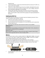
Installing the CPU Fan
The following instructions will guide you through the heat sink installation procedures. Please
consult your agent for the proper CPU cooler set.
1.
Position your CPU cooler set onto the CPU.
2.
Use one end of the clip to hook the latch of the CPU sliding plate.
3.
Hook the other latch to fix the cooling fan set. You may need a screw drive to press down
the other side of the clip.
4.
Connect the fan to the power supply connector provided on your mainboard.
MSI Reminds You...
Overheating…
Overheating will seriously damage the CPU and system; always make sure the cooling fan can
work properly to protect the CPU from overheating.
Replacing the CPU…
While replacing the CPU, always turn off the ATX power supply or unplug the power supply’s
power cord from grounded outlet first to ensure the safety of CPU.
Memory
The mainboard provides two 184-pin unbuffered DDR333 / DDR400 DDR SDRAM, and supports
the memory size up to 2GB. To operate properly, at least one DIMM module must be installed.
(For the updated supporting memory modules, please visit
http://www.msi.com.tw/program/products/mainboard/mbd/pro_mbd_trp_list.php )
Install at least one DIMM module on the slots. Memory modules can be installed on the slots in
any order. You can install either single- or double-sided modules to meet your own needs.
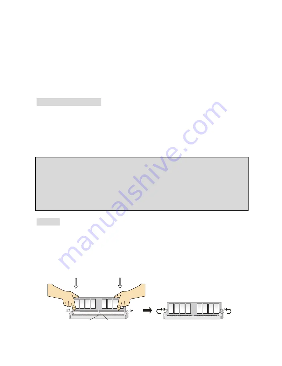
Installing DDR Modules
1.
The DDR DIMM has only one notch on the center of module. The module will only fit in the
right orientation.
Notch
Volt
Summary of Contents for MS-7119
Page 4: ...iv Table of Content English 1 Fran ais 15 Deutsch 28 41 53 65...
Page 54: ...50 BIOS Save Exit Setup CMOS Setup Exit Without Saving CMOS Setup...
Page 56: ...52 BIOS BIOS MSI http www msi com tw...
Page 67: ...63 Cell Menu DDR Optimized SPD High Performance Turbo Manual CPU FSB CPU 100MHz 300MHz 1MHz...
Page 68: ...64 BIOS BIOS http www msi com tw...
Page 81: ...77 Load Optimized Default Optimized default BIOS BIOS PC Save Exit...


