background image

5 - 2


M S-7176  ATX  M ainboard

BIOS Configuration

The Intel Matrix Storage Manager Option ROM should be integrated with the

system BIOS on all motherboards with a supported Intel chipset. The Intel Matrix

Stroage Manager Option ROM is the Intel RAID implementation and provides BIOS and

DOS disk services. Please use <Ctrl> + <I> keys to enter the 

Intel(R) RAID for Serial

ATA

 status screen, which should  appear early in system boot-up, during the POST

(Power-On Self Test). Also, you need to enable the RAID function in BIOS (please to

P.3-14 items 

SATA  Mode  <RAID> 

for details)  to create,  delete and  reset RAID

volumes.

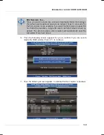
After the above message shows, press <Ctrl> and <I> keys simultaneously

to enter the RAID Configuration Utility.

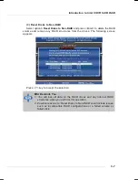
Using the Intel Matrix Stroage Manager Option ROM

1. Creating, Deleting and Resetting RAID Volumes:

The Serial ATA RAID volume may be configured using the RAID Configuration

utility stored within the Intel RAID Option ROM. During the Power-On Self Test (POST),

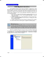
the following message will appear for a few seconds:

MSI Reminds You...

The 

Driver Model

Serial #

 and 

Size

 in the following example might

be different from your system.

MSI Reminds You...

The following procedure is only available with a newly-built system or if
you are reinstalling your OS. It should not be used to migrate an exist-
ing system to RAID.

Summary of Contents for MS-7176

Page 1: ...i G52 M7176X8 MS 7176 v1 X ATX Mainboard 945G Series...

Page 2: ...ent in a residential area is likely to cause harmful interference in which case the user will be required to correct the interference at his own expense Notice 1 The changes or modifications not expre...

Page 3: ...of NVIDIA Corporation in the United States and or other countries Netware is a registered trademark of Novell Inc Award is a registered trademark of Phoenix Technologies Ltd AMI is a registered trade...

Page 4: ...rd or module 9 All cautions and warnings on the equipment should be noted 10 Never pour any liquid into the opening that could damage or cause electrical shock 11 If any of the following situations ar...

Page 5: ...v WEEE Statement...

Page 6: ...vi...

Page 7: ...vii...

Page 8: ...tion to DDR2 SDRAM 2 7 Memory Module Population Rules 2 7 Installing DDR2 Modules 2 8 Power Supply 2 9 ATX 24 Pin Power Connector ATX1 2 9 ATX 12V Power Connector JPW1 2 9 Mouse Keyboard Connector 2 1...

Page 9: ...IOS Setup 3 1 Entering Setup 3 2 The Main Menu 3 3 Standard CMOS Features 3 5 Advanced BIOS Features 3 7 Advanced Chipset Features 3 10 Integrated Peripherals 3 11 Power Management Features 3 15 PNP P...

Page 10: ...roduction 6 2 BIOS Configuration 6 4 Create Disk Array 6 5 Delete Disk Array 6 8 Create and Delete Spare Hard Drive 6 9 Select Boot Array 6 10 View Serial Number of Hard Drive 6 10 Duplicate Critical...

Page 11: ...mainboard The 945G Series mainboard is based on Intel 945G and Intel ICH7 ICH7R chipset for optimal system efficiency Designed to fit the advanced Intel Pentium 4 Prescott LGA775 processor the 945G Se...

Page 12: ...CH7R chipset optional Hi Speed USB USB2 0 controller 480Mb sec up to 8 ports 4 SATAII ports with transfer rate up to 3Gb s 1 channel Ultra ATA 100 bus Master IDE controller PCI Master v2 3 I O APIC AC...

Page 13: ...t SPDIF Out Side Speaker Out 8 USB ports Rear 4 Front 4 1 RJ 45 LAN jack LAN Intel 82573V Supports 10 100 1000 Mb s Compliane with PCI 2 2 Supports ACPI Power Management 1394 optional Supports two IEE...

Page 14: ...Intel ICH7 ICH7R 945G JPW1 ATX1 IDE1 FDD1 CPUFAN1 Winbond W83627THG Top mouse Bottom keyboard Top Parallel Port Bottom COM port VGA port USB ports T M B Line In Line Out Mic T RS Out M CS Out B SPDIF...

Page 15: ...uide D Bracket 2 Optional MSI motherboard MSI Driver Utility CD Standard Cable for IDE Devices Back IO Shield Standard Cable for Floppy Disk The pictures are for reference only and may vary from the p...

Page 16: ...les and expansion cards as well as how to setup the jumpers on the mainboard Also it provides the instructions on connecting the periph eral devices such as the mouse keyboard etc While doing the inst...

Page 17: ...2 2 MS 7176 ATX Mainboard Quick Components Guide...

Page 18: ...from overheating Replacing the CPU While replacing the CPU always turn off the ATX power supply or unplug the power supply s power cord from grounded outlet first to ensure the safety of CPU Overcloc...

Page 19: ...on the bottom to protect the CPU contact from damage Rotate it to make the pin 1 indicator yellow triangle in the right bottom corner 2 Take out the accompanying CPU Clip and rotate it for the same d...

Page 20: ...pins of socket reveal 7 Lift the load lever up and open the load plate 8 Correctly align the triangle of CPU Clip with the CPU chamfer and the square on the CPU Clip to the hook of the socket 9 Use yo...

Page 21: ...e lever with the hook under reten tion tab 11 Visually inspect if the CPU is seated well into the socket then remove the CPU Clip with 2 fingers Then cover the load plate onto the package 13 Align the...

Page 22: ...or DDR1 and requires 28 less power than DDR1 chips DDR2 truly is the future of memory but will require some changes as the technology is not backwardly compatible and only motherboards specifically de...

Page 23: ...512MB 2GB 256MB 1GB 256MB 1GB 512MB 2GB 256MB 1GB 256MB 1GB 256MB 1GB 256MB 1GB 1GB 4GB ORANGE ORANGE GREEN GREEN MSI Reminds You Dual channel DDR works ONLY in the 5 combinations listed in the table...

Page 24: ...the ATX 24 pin power supply make sure the plug of the power supply is inserted in the proper orientation and the pins are aligned Then push down the power supply firmly into the connector ATX 12V Pow...

Page 25: ...PS 2 mouse keyboard directly into this connector The connector location and pin assignments are as follows PS 2 Mouse Keyboard 6 pin Female 2 1 3 4 5 6 PIN SIGNAL DESCRIPTION 1 Mouse Keyboard Data Mou...

Page 26: ...tors The mainboard provides an OHCI Open Host Controller Interface Universal Serial Bus root for attaching USB devices such as keyboard mouse or other USB compatible devices You can plug the USB devic...

Page 27: ...tion provided by Realtek ALC880 to offer support for 7 1 channel audio operation and can turn rear audio connectors from 2 channel to 4 5 1 7 1 channel audio Giga bit LAN Pin Definition PIN SIGNAL DES...

Page 28: ...P mode 13 1 14 25 PIN SIGNAL DESCRIPTION 1 STROBE Strobe 2 DATA0 Data0 3 DATA1 Data1 4 DATA2 Data2 5 DATA3 Data3 6 DATA4 Data4 7 DATA5 Data5 8 DATA6 Data6 9 DATA7 Data7 10 ACK Acknowledge 11 BUSY Busy...

Page 29: ...ositive and should be connected to the 12V the black wire is Ground and should be connected to GND If the mainboard has a System Hardware Monitor chipset on board you must use a specially designed fan...

Page 30: ...ary IDE Connector IDE2 Second IDE Connector IDE3 Third IDE connector Each one can connect a Master and a Slave drive You must configure second hard drive to Slave mode by setting the jumper accordingl...

Page 31: ...h connectors are fully compliant with Serial ATA 1 0 and 2 0 specifications Each Serial ATA connector can connect to 1 hard disk device PIN SIGNAL PIN SIGNAL 1 GND 2 TXP 3 TXN 4 GND 5 RXN 6 RXP 7 GND...

Page 32: ..._LED_P Hard disk LED pull up 2 FPPWR SLP MSG LED pull up 3 HD_LED_N Hard disk active LED 4 FPPWR SLP MSG LED pull up 5 RST_SW_N Reset Switch low reference pull down to GND 6 PWR_SW_P PowerSwitch high...

Page 33: ...1 VCC 2 VCC 3 USB0 4 USB1 5 USB0 6 USB1 7 GND 8 GND 9 Key 10 USBOC JUSB1 JUSB2 Pin Definition PIN SIGNAL DESCRIPTION 1 PORT 1L Analog Port 1 Left channel 2 GND Ground 3 PORT 1R Analog Port 1 Right cha...

Page 34: ...that allow you to connect optional IEEE 1394 port J1394_1 J1394_2 9 2 10 1 Pin Definition PIN SIGNAL PIN SIGNAL 1 TPA 2 TPA 3 Ground 4 Ground 5 TPB 6 TPB 7 Cable power 8 Cablepower 9 Key no pin 10 Gro...

Page 35: ...or green color 8 DBR4 high for red color 9 Key 10 NC Pin Definition JDB1 1 9 2 10 D Bracket 2 Optional Connected to JUSB1 the USB pinheader in YELLOW color Connected to JDB1 LEDs D Bracket 2 is an ext...

Page 36: ...essing BIOS image to RAM for fast booting Initializing Keyboard Controller Testing VGA BIOS This will start writing VGA sign on message to the screen Processor Initialization This will show informatio...

Page 37: ...ler D Bracket 2 Description Initializing Floppy Drive Controller This will initialize Floppy Drive and controller Boot Attempt This will set low stack and boot via INT 19h Operating System Booting JLP...

Page 38: ...configuration use the JBAT1 Clear CMOS Jumper to clear data Follow the instructions below to clear the data Jumpers MSI Reminds You You can clear CMOS by shorting 2 3 pin while the system is off Then...

Page 39: ...rpose I O Also desktop platforms with PCI Express Architecture will be designed to deliver highest performance in video graphics multimedia and other sophisticated applications Moreover PCI Express ar...

Page 40: ...der 3 Order 4 PCI Slot 1 INTA INT B INTC INTD PCI Slot 2 INT B INTC INTD INTA PCI Slot 3 INTC INTD INTA INT B PCI Slots PCI Peripheral Component Interconnect Slots The PCI slots allow you to insert th...

Page 41: ...OS category described in this chapter are under continuous update for better system performance Therefore the description may be slightly different from the latest BIOS and should be held for referenc...

Page 42: ...em The on line description for the selected setup category is displayed at the bottom of the screen Default Settings The preset Optimal Defaults of the BIOS setup program provide optimal performance s...

Page 43: ...menu to specify your settings for integrated peripherals Power Management Setup Use this menu to specify your settings for power management PNP PCI Configurations This entry appears if your system sup...

Page 44: ...mance Load Optimized Defaults Use this menu to load the default values set by the mainboard manufacturer specifically for optimal performance of the mainboard BIOS Setting Password Use these two menus...

Page 45: ...d by BIOS Read only month The month from Jan through Dec date The date from 1 to 31 can be keyed by numeric function keys year The year can be adjusted by users Time hh mm ss This allows you to set th...

Page 46: ...der Number of cylinders Head Number of heads Precomp Write precompensation Landing Zone Cylinder location of the landing zone Sector Number of sectors Drive A This item allows you to set the type of t...

Page 47: ...Down key to move it up down in this hard disk boot priority list Boot Sequence Press Enter to enter the sub menu The original IBM PCs loaded the DOS operating system from drive A floppy disk so IBM PC...

Page 48: ...o compliance with PC2001 design guide the system is able to run in APIC mode Enabling APIC mode will expand available IRQ resources for the system Settings Enabled Disabled CPU L3 Cache Level 3 cache...

Page 49: ...l com info hyperthreading MPS Table Version This field allows you to select which MPS Multi Processor Specification version to be used for the operating system You need to select the MPS version suppo...

Page 50: ...to improve performance certain space in memory can be reserved for ISA peripherals This memory must be mapped into the memory space below 16MB When this area is reserved it cannot be cached Settings D...

Page 51: ...USB keyboard mouse in the operating system that does not support or does not have any USB driver installed such as DOS and SCO Unix Settings Enabled Disabled Azalia AC97 Audio Select This item allows...

Page 52: ...2 378 IRQ7 Line Printer port 1 Parallel Port Mode SPP Standard Parallel Port EPP Enhanced Parallel Port ECP Extended Capability Port ECP EPP Extended Capability Port Enhanced Parallel Port To operate...

Page 53: ...hip Primary PCI IDE The integrated peripheral controller contains an IDE interface with support for the IDE channel Choose Enabled to activate the channel Setting options Enabled Disabled IDE Primary...

Page 54: ...ls with S ATA and P ATA devices and maximum of 2 devices in each channel are supported maxinum of 4 devices Refer to the table below for the combination Enhanced Mode This mode can enable both S ATA a...

Page 55: ...your operating system supports ACPI such as Windows 98SE Windows ME and Windows 2000 you can choose to enter the Standby mode in S1 POS or S3 STR fashion through the setting of this field Options are...

Page 56: ...conds the computer is turned off Wakeup Event Setup Press Enter and the following sub menu appears Resume by PCI Device PME When setting to Enabled this setting allows your system to be awakened by PC...

Page 57: ...the system Hot Key Power ON If POWER ON Function is set to Hot KEY you can assign a hot key combination in the field for the PS 2 keyboard to power on the system Settings Ctrl F1 through Ctrl F12 Res...

Page 58: ...e ISA VGA device s palette registers permitting the palette registers of both VGA devices to be identical PNP PCI Configurations This section describes configuring the PCI bus system and PnP Plug Play...

Page 59: ...5 7 9 10 11 12 14 15 Auto Selecting Auto allows BIOS to automatically deter mine the IRQ line for each PCI slot PCI Express relative items Maximum Payload Size This item allows you to set the maximum...

Page 60: ...message set the field to Reset The setting of the field will automatically return to Enabled later Setting options Enabled Reset Disabled PC Health Status Press Enter and the following sub menu appear...

Page 61: ...DDR timing setting Setting to Optimized enables Adjust DDR Memory Frequency automatically to be determined by SPD Selecting Manual allows users to configure these fields manually Setting options Optim...

Page 62: ...omplete and DRAM may fail to retain data This item applies only when synchronous DRAM is installed in the system Available settings 4 3 2 clocks Precharge Delay tRAS The field specifies the idle cycle...

Page 63: ...ing first 2 Meanwhile there are two functions to protect user s system from crash There is a safe key Ins in BIOS In case the overclocking fails you can press Ins key while system rebooting to restore...

Page 64: ...clock frequency of CPU host bus FSB AGP 3V66 and PCI bus It provides a method for end users to overclock the processor Setting options Give a DEC value by entering a number between maximum 265 MHz to...

Page 65: ...r specifically for optimal performance of the mainboard The Fail Safe Defaults are the default values set by the BIOS vendor for stable system performance When you select Load Fail Safe Defaults a mes...

Page 66: ...ou may also press Esc to abort the selection and not enter a password To clear a set password just press Enter when you are prompted to enter the password A message will show up confirming the passwor...

Page 67: ...anagement and communication 802 11g WLAN settings Moreover with this unique utility you will be able to activate the MSI well known features Live Update and Core Center which makes it easier to update...

Page 68: ...menu to make further configuration MSI Click on this button to link to MSI website http www msi com tw Quick Guide Click on this button and the quick guide of DigiCell will be displayed for you to re...

Page 69: ...tem this icon will be lit up Click this blue icon to turn DigiCell into a MP3 player and then you can load media files from your MEGA STICK or the system and edit the preferred playlist Audio Speaker...

Page 70: ...stic sub menu you can see the information status and note of each DigiCell You may double check the connection and installation of the item marked as gray You may also click on the Mail to MSI button...

Page 71: ...your system Click on each item for details This icon indicates the information and connection status of onboard LAN which is read only The second icon indicates the wireless connection You may click t...

Page 72: ...network is a local area network or other small network especially one with wireless or temporary plug in connections in which some of the network devices are part of the network only for the duration...

Page 73: ...mputers simultaneously 2 If you are getting on Internet in office usually the LAN card will automatically get the IP this computer uses In this case you don t have to enable this function SSID Means S...

Page 74: ...tion column the screen will display as below You need to enter the correct WEP key defined by AP in the specified WEP Key 1 4 fields to make the connection Association Control This option allows you t...

Page 75: ...on the right will appear on the screen Double click the MSI Live Update 3 icon and the following screen will appear Several buttons are placed on the left column of the screen Click the desired butto...

Page 76: ...the Play List field and use Delete button to remove the media file from the play list You may remove multi media files simultaneously by using Ctrl to select multi files Shuffle To play the media file...

Page 77: ...rewind Right click on the MP3 file and choose Info a MP3 Info dialogue will pop up to show the information of the file including the title artist album release year and others You may also add your o...

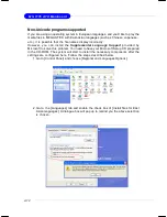
Page 78: ...install the Supplemental Language Support provided by Microsoft to solve this problem You need to have your Microsoft Setup CD prepared in the CD ROM The system will start to install the necessary com...

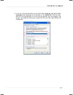
Page 79: ...select the language you want to be supported the language of the filename in the MegaStick from the drop down list in the Language for non Unicode programs then click Apply The system will install th...

Page 80: ...st the PC hardware and system status during real time operation In the left side it shows the current system status including the Vcore 3 3V 5V and 12V In the right side it shows the current PC hardwa...

Page 81: ...so you may click Auto to start testing the maximum CPU overclocking value The CPU FSB will automatically increase the testing value until the PC reboots Or you may click Default to restore the default...

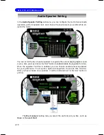
Page 82: ...er to regulate the current playing digital sound source Also you may click on the on button to enable disable the equalizer function Once the equalizer function is enabled you can choose several prese...

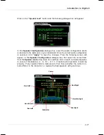
Page 83: ...nges Then the following screen will appear In this Speaker Configuration dialogue box first select the correct item from the Speaker mode drop down list and then click on each connected speaker to ens...

Page 84: ...on Date Use the drop down list to select the date for power on Time Use the arrow keys to select the hour minute second for power on power off and restarting Then click Apply to save the changes As yo...

Page 85: ...r Step 2 Click on OK to apply the setting Step 3 For specified file or specified website you may enter the file name with the complete path or the website link in the Parameters field Of course you ma...

Page 86: ...eature It supports the following operating systems Win9X Windows ME Windows 2000 Windows XP Default User Name It is only available for Windows 2000 Windows XP If you are using a computer belonging to...

Page 87: ...logy RAID 0 breaks the data into blocks which are written to separate hard drives Spreading the hard drive I O load across independent chan nels greatly improves I O performance RAID 1 provides data r...

Page 88: ...etails to create delete and reset RAID volumes After the above message shows press Ctrl and I keys simultaneously to enter the RAID Configuration Utility Using the Intel Matrix Stroage Manager Option...

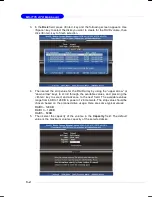
Page 89: ...appear 1 Create RAID Volume 1 Select option 1 Create RAID Volume and press Enter key The following screen appears Then in the Name field specify a RAID Volume name and then press the TAB or Enter key...

Page 90: ...pper arrow or down arrow keys to scroll through the available values and pressing the Enter key to select and advance to the next field The available values range from 4KB to 128 KB in power of 2 incr...

Page 91: ...creation is finished MSI Reminds You Since you want to create two volumes Intel Matrix RAID Technology this default size maximum needs to be reduced Type in a new size for the first volume As an examp...

Page 92: ...ID Volume from the main menu window and press Enter key to select a RAID volume for deletion Then press Delete key to delete the selected RAID volume The following screen appears Press Y key to accept...

Page 93: ...RAID structures from the drives The following screen appears Press Y key to accept the selection MSI Reminds You 1 You will lose all data on the RAID drives and any internal RAID structures when you...

Page 94: ...n or if you need to specify any additional devices to be installed do so at this time Once all devices are specified press Enter to continue with installation 6 From the Windows XP 2000 Setup screen p...

Page 95: ...hard drive from which the system is booting or a hard drive that contains impor tant data For this reason you cannot remove or un install this driver from the system after installation however you wi...

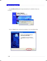
Page 96: ...5 10 MS 7176 ATX Mainboard The InstallShield Wizard will begin automatically for installation showed as following Click on the Next button to proceed the installation in the welcoming window...

Page 97: ...Introduction to Intel ICH7R SATA RAID After reading the license agreement in the following window click Yes button to continue The window shows the components to be installed Click Next button to cont...

Page 98: ...Select the folder in which you want the program to be installed in the following window and click Next button to start installation Select a program folder in the following window where you want Setu...

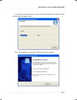
Page 99: ...roduction to Intel ICH7R SATA RAID Once the installation is complete the following window appears The following window appears to show the Intel Application Accelerator RAID Edition Setup installation...

Page 100: ...ation Accelerator RAID Driver during Windows Setup Refer to Installing Software for instructions on installing the driver during Windows Setup 3 Install the Intel Matrix Storage Console after the oper...

Page 101: ...Volume from Existing Disk To create a RAID volume from an existing disk choose Action Create RAID Volume from Existing Hard Drive The Create RAID Volume from Existing Hard Drive Wizard pops up to lead...

Page 102: ...dancy will provide you with a realtime duplicate copy of your data Note Only half of the available volume space will be avail able for data storage RAID 5 Useful RAID 5 can be used on three or more di...

Page 103: ...le to calculate the correct parity information or similar to RAID 1 writes The write efficiency depends heavily on the amount of memory in the machine and the usage pattern of the array Heavily scatte...

Page 104: ...r disk the target disk that you wish to use and then click to move it to the Selected field Then click Next to continue Please note that the existing data on the selected hard drive s will be deleted...

Page 105: ...ard drive space will be worked as RAID 1 volume which is the new technology called Intel Matrix RAID Then click Next to continue 5 Start Creating RAID Volume from Existing Hard Drive Wizard Before you...

Page 106: ...e you can still continue using your computer during the migration process once the migration process starts it cannot be stopped If the migration process gets inter rupted and your system is rebooted...

Page 107: ...channels and maximum connection of four hard disk drives allowed 4 Supports Ultra DMA mode 6 5 4 3 2 1 0 DMA mode 2 1 0 and PIO mode 4 3 2 1 0 5 Supports PCI Plug and Play PCI interrupt sharing and co...

Page 108: ...sical drive to the operating system Hard disk drives can be combined together through a few different methods The different methods are referred to as different RAID levels Different RAID levels repre...

Page 109: ...the data access Another unique feature of RAID 0 1 is dual fault tolerance In some cases two drives can fail simultaneously and still maintain the integrity of the data The data can still be accessed...

Page 110: ...b key to enter the BIOS configuration The VIA IDE RAID volume may be configured using the VIA Tech RAID BIOS Always use the arrow keys to navigate the main menu use up and down arrow key to select eac...

Page 111: ...press Enter a list of array modes will appear Highlight the target array mode that you want to create and press Enter to confirm the selection If RAID 1 or RAID 0 1 is selected an option list will po...

Page 112: ...Drives Auto Setup allows BIOS to select the disk drives and create arrays automatically but it does not duplicate the mirroring drives even if the user selected Create and dupli cate for RAID 1 It is...

Page 113: ...ontent in the hard drive will be destroyed after array creation MSI Reminds You Even though 64KB is the recommended setting for most users you should choose the block size value which is best suited t...

Page 114: ...Enter The channel column will be activated 2 Select the member of an array that is to be deleted and press Enter A warning message will show up press Y to delete or press N to cancel Deleting a disk a...

Page 115: ...can be selected as a spare drive for the RAID 1 array Select Create Delete Spare and press Enter the channel column will then be activated Select the drive that you want to use as a spare drive and pr...

Page 116: ...n If there are no disk arrays then nothing will be displayed on the screen Select Boot Array User can select a disk array as boot device if user wants to boot operating system from an array Boot disk...

Page 117: ...sistencies between user data and backup data If BIOS detects any inconsistencies the status of the disk array will be marked as critical and BIOS will prompt the user to duplicate the RAID 1 in order...

Page 118: ...D 1 or 0 1 array but there is no spare hard drive available for rebuilding the array BIOS will provide several operations to solve such problem 1 Power off and Check the Failed Drive This item turns o...

Page 119: ...er choosing a hard drive the channel column will be activated Highlight the target hard drive and press Enter a warning message will appear Press Y to use that hard drive to rebuild or press N to canc...

Page 120: ...on or if you need to specify any additional devices to be installed do so at this time Once all devices are specified press Enter to continue with installation 6 From the Windows XP 2000 Setup screen...

Page 121: ...package that enables high perform ance in the Windows XP 2000 operating system This version of VIA IDE RAID Utility contains the following key features IDE RAID driver VIA IDE RAID utility RAID0 RAID...

Page 122: ...llShield Wizard will begin automatically for installation Click on the Next button to proceed the installation in the welcoming window Select I Agree to accept the VIA Software License Agreement and c...

Page 123: ...IA VT6410 IDE RAID 6 17 Put a check mark in the check box to install the feature you want Then click Next button to proceed the installation Remember to restart your computer before using this newly i...

Page 124: ...ecific functions The left window pane displays the controller and disk drives The right window pane displays the details of the controller or disk drives In this model the available features are as fo...

Page 125: ...ils of each disk Click on or button to determine the viewing type of left window pane There are two viewing types By controllers and by device Click on the object in the left window pane to display th...

Page 126: ...MS 7176 ATX Mainboard 6 20 Click on the plus symbol next to Array 0 RAID 1 to see the details of each disk You may also use the same or button to view the status of Array 0 RAID 1...

Page 127: ...ides sup port for 7 1 2 channel audio output including 2 Front 2 Rear 2 Side 1 Center 1 Subwoofer and 2 Front Pannel channel ALC882 allows the board to attach 2 4 6 or 8 speakers for better surround s...

Page 128: ...ows XP you must install Windows XP Service Pack1 or later before installing the driver The following illustrations are based on Windows XP environment and could look slightly different if you install...

Page 129: ...7 3 Introduction to Realtek ALC 882 4 Click Finish to restart the system 3 Click Next to install the Realtek High Definition Audio Driver Click here Click here Select this option...

Page 130: ...o use the 2 4 6 or 8 channel audio feature now Click the audio icon from the system tray at the lower right corner of the screen to activate the HD Audio Configuration It is also available to enable t...

Page 131: ...e a preset EQ setting There are also other pre set equalizer models for you to choose by clicking Others under the Equalizer part Load EQ Setting Reset EQ Setting Save Preset Delete EQ Setting EQ Sett...

Page 132: ...t without losing the settings Load Whenever you would like to use preload settings simply click this the whole list will be shown for your selection Delete To delete the pre saved settings which are c...

Page 133: ...ile the background music is still in place and you can be that singer 2 Key Adjustment Using Up Down Arrow to find a key which better fits your vocal range Raise the key Lower the key Remove the human...

Page 134: ...ely from the indicated real panel or front panel This feature is very helpful when 2 people are using the same computer together for different purposes Click the button and the Mixer ToolBox menu will...

Page 135: ...played from the rear panel which is the default setting Then you must to select the Realtek HD Audio front output from the scroll list first and use a different program to play the second audio source...

Page 136: ...ltiple volume controls or to completely mute sound output Tool Show the following volume controls This is to let you freely decide which volume control items to be displayed total 13 items to be chose...

Page 137: ...ich volume control items to be displayed Advanced controls Advanced control is a Microphone Boost icon Once this item is checked you will find advanced icon beside Front Pink In Mic Volume With this t...

Page 138: ...be chosen to perform either output i e playback function or input i e Recording function we call this Retasking Audio I O aims to help you set jacks right Moreover other than blue to blue pink to pin...

Page 139: ...le and the dialogue connected device pops up the default setting of blue jack is Line in Check the headphone anyway then click OK You should notice the icon beside blue jack remains the same without a...

Page 140: ...no function on front panel jacks Please check if front jacks on your system are so called AC 97 jacks If so please check this item to disable front panel jack detection 2 Enable auto popup dialogue w...

Page 141: ...ital signal prevents the quality of the signal from degrading when it is converted to analog 1 Output Sampling Rate 44 1KHz This is recommend while playing CD 48KHz This is recommended while playing D...

Page 142: ...up and make testing sound If any speaker fails to make sound then check whether the cable is inserted firmly to the connector or replace the bad speakers with good ones Or you may click the auto test...

Page 143: ...or example you might have chance to use VOIP function through Internet with your friends The voice of your friend will come out from speakers playback However the voice of your friend might also be re...

Page 144: ...Mainboard 3D Audio Demo In this tab you may adjust your 3D positional audio before playing 3D audio applications like gaming You may also select different environment to choose the most suitable envi...

Page 145: ...ersion Audio Controller Audio Codec You may also select the language of this utility by choosing from the Language list Also there is a selection Show icon in system tray Switch it on and an icon will...

Page 146: ...are Setup 2 Select Enable for Azalia Disable for AC 97 in the Azalia AC97 Audio Select BIOS setting Please refer to Chapter 3 3 If you are using Azalia setting the microphone function on the front pan...

Page 147: ...it 2 Advanced Controls provides you more controls over DTS Neo PC Single click on Tool button to access advanced controls 2 1 DTS Neo PC Cinema mode The Cinema mode is for use with stereo television s...

Page 148: ...6 ATX Mainboard Wide mode This extends the front stereo image to include the surround speakers It is particularly effective for recordings that have left or right channel elements in the mix Figure 2...

Page 149: ...dance with the setting in software utility n 2 Channel Mode for Stereo Speaker Output Refer to the following diagram and caption for the function of each phone jack on the back panel when 2 Channel Mo...

Page 150: ...ck panel s Line Out connector and two speakers to the real chan nel Line Out connector 3 1 2 6 4 5 1 Line In 2 Line Out Front channels 3 MIC 4 Line Out Rear channels 5 Line Out Center and Subwoofer ch...

Page 151: ...panel s Line Out connector two speakers to the rear channel and two speakers to the cen ter subwoofer channel Line Out connectors 6 Channel Analog Audio Output 1 Line In 2 Line Out Front channels 3 M...

Page 152: ...Out Front channels 3 MIC 4 Line Out Rear channels 5 Line Out Center and Subwoofer channel 6 Optical SPDIF jack Description Connect two speakers to back panel s Line Out connector two speakers to the...

Reviews: