background image

viii

CONTENTS

Chapter  1.  Getting  Started ............................................................................... 1-1

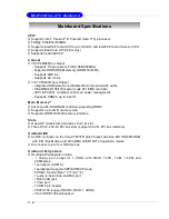
Mainboard Specifications ............................................................................... 1-2

Mainboard Layout ........................................................................................... 1-4

Packing Contents ............................................................................................ 1-5

MSI Special Feature ........................................................................................ 1-6

Chapter  2.  Hardware  Setup .............................................................................. 2-1

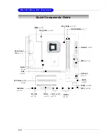
Quick Components Guide ............................................................................... 2-2

Central Processing Unit: CPU ......................................................................... 2-3

Introduction to LGA 775 CPU .................................................................. 2-3

CPU & Cooler Installation ......................................................................... 2-4

Memory ........................................................................................................... 2-7

Introduction to DDR2 SDRAM .................................................................. 2-7

Installing DDR2 Modules .......................................................................... 2-7

Power Supply ................................................................................................. 2-8

ATX 24-Pin Power Connector: CONN1 ................................................... 2-8

ATX 12V Power Connector: JPW2 ......................................................... 2-8

Back Panel ...................................................................................................... 2-9

Mouse/Keyboard Connector ................................................................... 2-9

VGA Connector ....................................................................................... 2-9

Serial Port Connector ............................................................................ 2-10

LAN (RJ-45) Jack (optional) ................................................................. 2-10

USB Connectors .................................................................................... 2-10

Audio Port Connectors .......................................................................... 2-11

Parallel Port Connector: LPT1 ............................................................... 2-12

Floppy Disk Drive Connector: FDD1 ...................................................... 2-13

Fan Power Connectors: CPU_FAN1/ SYS_FAN1 ................................. 2-13

Connectors ................................................................................................... 2-13

Hard Disk Connectors: IDE1, IDE2 ......................................................... 2-14

Serial Port Header: COM2 ............................................................................ 2-14

Serial ATA: SATA1,SATA2 ..................................................................... 2-15

Front Panel Connectors: JFP1 .............................................................. 2-16

CD-In, AUX_In Connector: CD_IN1 ........................................................ 2-16

Front Panel Audio Connector: JAUDIO1 ................................................ 2-17

Front USB Connectors: JUSB1 & JUSB2 .............................................. 2-18

IEEE 1394 Connectors (optional): 1394_J2/ 1394_J3 ........................... 2-19

Jumpers ........................................................................................................ 2-20

Clear CMOS Jumper: JBAT2 ................................................................. 2-20

Summary of Contents for MS-7222

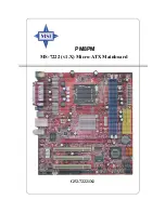
Page 1: ...i G52 72221X1 MS 7222 v1 X Micro ATX Mainboard PM8PM...

Page 2: ...radio communications However there is no guarantee that interference will not occur in a particular installation If this equipment does cause harmful interference to radio or television reception whic...

Page 3: ...s Corporation Microsoft is a registered trademark of Microsoft Corporation Windows 98 2000 NT XP are registered trademarks of Microsoft Corporation NVIDIA the NVIDIA logo DualNet and nForce are regist...

Page 4: ...vice personnel The power cord or plug is damaged Liquid has penetrated into the equipment The equipment has been exposed to moisture The equipment has not work well or you can not get it work accordin...

Page 5: ...v WEEE Statement...

Page 6: ...vi...

Page 7: ...vii...

Page 8: ...W2 2 8 Back Panel 2 9 Mouse Keyboard Connector 2 9 VGA Connector 2 9 Serial Port Connector 2 10 LAN RJ 45 Jack optional 2 10 USB Connectors 2 10 Audio Port Connectors 2 11 Parallel Port Connector LPT1...

Page 9: ...24 BIOS Setting Password 3 24 Chapter 4 Introduction to Realtek ALC655 4 1 Installing the Audio Driver 4 2 Using 4 or 6 Channel Audio Function 4 4 Testing the Connected Speakers 4 9 Playing KaraOK 4 1...

Page 10: ...ATX mainboard The PM8PM mainboard is based on VIA P4M800 Pro and VIA VT8237R Plus chipset for optimal system efficiency Designed to fit the advanced Intel Pentium 4 Prescott LGA775 processor the PM8P...

Page 11: ...up to 8 ports Main Memory Advanced 64 bit SDRAM controller supporting DDRII Supports up to 2GB memory size Supports DDRII 533 400 memory interface Slots One AGP Accelerated Graphics Port 8x slot Three...

Page 12: ...trolled by VIA6307 chipset BIOS The mainboard BIOS provides Plug Play BIOS which detects the peripheral devices and expansion cards of the board automatically The mainboard provides a Desktop Manageme...

Page 13: ...Winbond W83627EHF PLUS P4M800PRO VT8237R VT6307 IDE 1 SATA1 SATA2 DIMM1 DIMM2 IDE 2 FDD 1 JUSB1 JUSB2 JFP1 COM2 CPU_FAN1 AC97 Top LAN jack Bottom USB ports Bottom USB ports Top mouse Bottom keyboard...

Page 14: ...r s Guide MSI motherboard MSI Driver Utility CD Round Cable for IDE Devices Optional Round Cable for Floppy Disk Optional Back IO Shield COM2 Bracket Optional The pictures are for reference only Your...

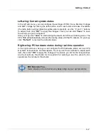
Page 15: ...essages The Core Center is a new utility you can find in the CD ROM disk The utility is just like your PC doctor that can detect view and adjust the PC hardware and system status during real time oper...

Page 16: ...ximum CPU overclocking value The CPU FSB will automatically increase the testing value until the PC reboots Or you may click Default to restore the default values Right wing PC hardware status during...

Page 17: ...les and expansion cards as well as how to setup the jumpers on the mainboard Also it provides the instructions on connecting the periph eral devices such as the mouse keyboard etc While doing the inst...

Page 18: ...p 2 7 CONN1 p 2 8 Back Panel I O p 2 9 JAUDIO1 p 2 17 PCI Slots 1 3 p 2 21 AGP p 2 21 CD_IN1 p 2 16 JPW2 p 2 8 SYS_FAN1 p 2 13 JFP1 p 2 16 1394_J2 3 p 2 19 FDD1 p 2 13 JUSB1 2 p 2 18 SATA1 2 p 2 15 I...

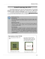
Page 19: ...from overheating Replacing the CPU While replacing the CPU always turn off the ATX power supply or unplug the power supply s power cord from grounded outlet first to ensure the safety of CPU Overcloc...

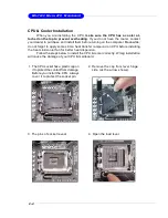
Page 20: ...to apply some silicon heat transfer compound on CPU before installing the heat sink cooler fan for better heat dispersion Follow the steps below to install the CPU cooler correctly Wrong installation...

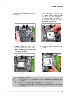
Page 21: ...CPU packing 6 After confirming the CPU direction for correct mating put down the CPU in the socket housing frame Be sure to grasp on the edge of the CPU base Note that the align ment keys are matched...

Page 22: ...e suggest you do not plug unplug the CPU too often 10 Align the holes on the mainboard with the heatsink Push down the cooler until its four clips get wedged into the holes of the mainboard 12 Turn ov...

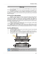
Page 23: ...and only motherboards specifically designed for DDR2 memory will be able to support these chips DDR2 incorporates new features at the chip level that give it better signal integrity thereby enabling h...

Page 24: ...GNAL 1 GND 2 GND 3 12V 4 12V JPW1 Pin Definition ATX 24 Pin Power Connector CONN1 The mainboard supports ATX power supply for the power system Before inserting the power supply connector always make s...

Page 25: ...ale 2 1 3 4 5 6 PIN SIGNAL DESCRIPTION 1 Mouse Keyboard Data Mouse Keyboard data 2 NC Noconnection 3 GND Ground 4 VCC 5V 5 Mouse KeyboardClock Mouse Keyboardclock 6 NC Noconnection Pin Definition Keyb...

Page 26: ...ional The mainboard provides 1 standard RJ 45 jack for connection to single Local Area Network LAN This LAN enables data to be transferred at 1000 8110SB 100 or 10Mbps You can connect a network cable...

Page 27: ...er 4 Introduction to Realtek ALC655 for details USB Connectors The mainboard provides an OHCI Open Host Controller Interface Universal Serial Bus root for attaching USB devices such as keyboard mouse...

Page 28: ...ort ECP mode 13 1 14 25 PIN SIGNAL DESCRIPTION 1 STROBE Strobe 2 DATA0 Data0 3 DATA1 Data1 4 DATA2 Data2 5 DATA3 Data3 6 DATA4 Data4 7 DATA5 Data5 8 DATA6 Data6 9 DATA7 Data7 10 ACK Acknowledge 1 1 BU...

Page 29: ...d connector When connecting the wire to the connectors always take note that the red wire is the positive and should be connected to the 12V the black wire is Ground and should be connected to GND If...

Page 30: ...ll two hard disks on cable you must configure the second drive to Slave mode by setting its jumper Refer to the hard disk documentation supplied by hard disk vendors for jumper setting instructions ID...

Page 31: ...are fully compliant with Serial ATA 1 0 specifications Each Serial ATA connector can connect to 1 hard disk device PIN SIGNAL PIN SIGNAL 1 GND 2 TXP 3 TXN 4 GND 5 RXN 6 RXP 7 GND SATA Pin Definition M...

Page 32: ...l Front Panel I O Connectivity Design Guide PIN SIGNAL DESCRIPTION 1 HD_LED_P Hard disk LED pull up 2 FPPWR SLP MSG LED pull up 3 HD_LED_N Hard diskactive LED 4 FPPWR SLP MSG LED pull up 5 RST_SW_N Re...

Page 33: ...by analog audio circuits 5 AUD_FPOUT_R Right channel audio signal to front panel 6 AUD_RET_R Right channel audio signal return fromfront panel 7 HP_ON Reservedfor futureuseto control headphone amplif...

Page 34: ...roughput of 480Mbps which is 40 times faster than USB 1 1 and is ideal for connecting high speed USB interface peripherals such as USB HDD digital cameras MP3 players printers modems and the like PIN...

Page 35: ...s you to connect IEEE 1394 ports via an external IEEE1394 bracket optional Foolproof design Connected to 1394 connectors The Green connectors IEEE1394 Bracket Optional 1394_J2 1394_J3 1 2 9 10 Pin Def...

Page 36: ...is turned on If you want to clear the system configuration use the JBAT2 Clear CMOS Jumper to clear data Follow the instructions below to clear the data Jumpers MSI Reminds You You can clear CMOS by s...

Page 37: ...hannel for the graphics controller to directly access main memory The slot supports 8x 4x AGP card PCI Peripheral Component Interconnect Slots The PCI slots allow you to insert the expansion cards to...

Page 38: ...bed in this chapter are under continuous update for better system performance Therefore the description may be slightly different from the latest BIOS and should be held for reference only 2 While boo...

Page 39: ...menu or returns to the main menu from a submenu Increase the numeric value or make changes Decrease the numeric value or make changes F10 Save and Exit Setup MSI Reminds You The items under each BIOS...

Page 40: ...system s performance Integrated Peripherals Use this menu to specify your settings for integrated peripherals Power Management Features Use this menu to specify your settings for power management PNP...

Page 41: ...he default values set by the mainboard manufacturer specifi cally for optimal performance of the mainboard BIOS Setting Password Use this menu to set the password for BIOS Save Exit Setup Save changes...

Page 42: ...te from 1 to 31 can be keyed by numeric function keys year The year can be adjusted by users Time hh mm ss This allows you to set the system time that you want usually the current time The time format...

Page 43: ...B 3 1 2 Halt On The setting determines whether the system will stop if an error is detected at boot Available options are No Errors The system doesn t stop for any detected error All But Keyboard The...

Page 44: ...When you choose No you cannot run the OS 2 operating system with DRAM larger than 64MB But it is possible if you choose Yes Full Screen LOGO Show This item enables you to show the company logo on the...

Page 45: ...options 1 4 1 1 Boot Sequence Press Enter and the following sub menu appears 1st 2nd 3rd Boot Device These items allow you to set the sequence of boot devices where AMIBIOS attempts to load the operat...

Page 46: ...e these settings only if you are familiar with the chipset DRAM Clock Use this field to configure the clock frequency of the installed DRAM Settings By SPD DDR 266 3 2 DDR 333 6 5 DDR 400 1 1 DDR 433...

Page 47: ...incomplete and DRAM may fail to retain data This item applies only when synchronous DRAM is installed in the system Setting options 2T 3T 4T 5T Active to Precharge Tras This item controls the number o...

Page 48: ...ontrols the DQS Input Capture Range for channel A Setting options Auto Manual RDSAIT Selection This setting allows you to adjust the RDSAIT value AGP P2P Bridge Control Press Enter and the following s...

Page 49: ...ycle Setting options Enabled Disabled AGP 3 0 Calibration cycle This setting disables enables the AGP auto calibration Setting options Disabled Enabled VGA Share Memory Size The system shares memory t...

Page 50: ...Setup VLink 8X Supported This item enables or disables the 8X VLink Data Rate Setting options Enabled Disabled DRDY_Timing This item allows you to set the DRDY timing Setting options Slowest Default...

Page 51: ...in the operating system that does not support or have any USB 1 1 2 0 driver installed such as DOS Set to Disabled only if you want to use any USB device other than the USB mouse Setting options Disa...

Page 52: ...enter the sub menu and the following screen appears OnChip SATA The integrated peripheral controller contains a SATA interface with support for two SATA channels Select Enabled to activate the SATA i...

Page 53: ...rt address of the onboard parallel port Select ing Auto allows AMIBIOS to automatically determine the correct base I O port address Setting options 378 278 3BC and Disabled Parallel Port Mode This ite...

Page 54: ...S The S1 sleep mode is a low power state In this state no system context is lost CPU or chipset and hardware maintains all system context S3 STR The S3 sleep mode is a lower power state where the info...

Page 55: ...wer on state Last State Restores the system to the previous status before power failure or interrupt occurred Wake Up Event Setup Press Enter and the following sub menu appears Resume From S3 by USB D...

Page 56: ...mouse is detected Setting options Disabled Enabled Resume by PCI Device PME When setting to Enabled this setting allows your system to be awakened from the power saving modes through any event on PME...

Page 57: ...g options are AGP The system initializes the installed AGP card first If an AGP card is not available it will initialize the PCI VGA or Internal VGA card PCI The system initializes the installed PCI V...

Page 58: ...ble by the system BIOS The available IRQ pool is determined by reading the ESCD NVRAM If more IRQs must be removed from the IRQ pool the end user can use these settings to reserve the IRQ by assigning...

Page 59: ...the CPU overheating problem This item is available only when your OS supports this function such as Windows ME XP Setting options 80o C 176o C 85o C 185o C 90o C 194o C Disabled CPU Smart Fan Temperat...

Page 60: ...the following sub menu appears CPU System Temperature CPU System FAN Speed CPU Vcore 12V 5V 5V SB 3 3V These items display the current status of all of the monitored hardware devices components such...

Page 61: ...typed now will replace any previously set password from CMOS memory You will be prompted to confirm the password Retype the password and press Enter You may also press Esc to abort the selection and...

Page 62: ...o output including 2 Front 2 Rear 1 Center and 1 Subwoofer channel ALC655 allows the board to attach 4 or 6 speakers for better surround sound effect The section will tell you how to install and use 4...

Page 63: ...g illustrations are based on Windows XP environment and could look slightly different if you install the drivers in different operating systems 1 Insert the companion CD into the CD ROM drive The setu...

Page 64: ...4 3 Introduction to Realtek ALC655 3 Click Next to start installing files into the system 4 Click Finish to restart the system Select this option...

Page 65: ...ght corner of the screen 2 Select a desired surround sound effect from the Environment drop down menu 3 Click the Speaker Configuration tab 4 Select Synchronize the phonejack switch with the settings...

Page 66: ...4 5 Introduction to Realtek ALC655 2 3 4 5 6...

Page 67: ...utility connect your speakers to the correct phone jacks in accordance with the setting in software utility n 2 Channel Mode for Stereo Speaker Output Refer to the following diagram and caption for th...

Page 68: ...ode for 4 Speaker Output The audio jacks on the back panel always provide 2 channel analog audio output function however these audio jacks can be transformed to 4 or 6 channel analog audio jacks by se...

Page 69: ...ted n 6 Channel Mode for 6 Speaker Output Refer to the following diagram and caption for the function of each jack on the back panel when 6 Channel Mode is selected MSI Reminds You If the Center and S...

Page 70: ...rly you may need to test each connected speaker to make sure every speaker work properly If any speaker fails to make sound then check whether the cable is inserted firmly to the connector or replace...

Page 71: ...oard 4 While you are testing the speakers in 6 Channel Mode if the sound coming from the center speaker and subwoofer is swapped you should select Swap Center Subwoofer Output to readjust these two ch...

Page 72: ...ics and leave melody for you to sing the song Note that this function applies only for 2 channel audio operation Playing KaraOK 1 Click the audio icon from the window tray at the lower right corner of...

Page 73: ...pport two SATA two PATA hard disk drives 2 Only SATA supports RAID 3 Supports ATA 133 high performance hard disk drive 4 Dual independent ATA channels and maximum connection of four hard disk drives a...

Page 74: ...different performance levels security levels and implementation costs The RAID levels which the VIA VT8237R Plus SATA RAID Host Controller supports are RAID 0 and RAID 1 The table below briefly introd...

Page 75: ...ss press Tab key to enter the BIOS configuration The Serial ATA RAID volume may be configured using the VIA Tech RAID BIOS Always use the arrow keys to navigate the main menu use up and down arrow key...

Page 76: ...ter to confirm the selection If RAID 1 is selected an option list will popup and enable the users to select Create only or Create and duplicate Create only will allow BIOS to only create an array The...

Page 77: ...is Select Disk Drives Auto Setup allows BIOS to select the disk drives and create arrays automatically but it does not duplicate the mirroring drives even if the user selected Create and duplicate for...

Page 78: ...e two hard disk drives will be reserved and become two normal disk drives Use the arrow key to highlight Start Create Process and press Enter A warning message will appear Press Y to finish the creati...

Page 79: ...spare drive and press Enter the selected drive will be marked as Spare The spare drive cannot be accessed in an OS To delete a spare drive highlight Create Delete Spare and press Enter The spare driv...

Page 80: ...ing Continue to boot enables the user to duplicate the array after booting into operat ing system If BIOS detects a broken RAID 1 array but there is no spare hard drive available for rebuilding the ar...

Page 81: ...g disk will remain after the destroy operation However Destroy the Mirroring Relationship is not recommend because the data on the remaining disk will be lost when the hard drive is used to create ano...

Page 82: ...inue with installation 6 From the Windows XP Setup screen press the Enter key Setup will now load all device files and then continue the Windows XP installation Existing Windows XP Driver Installation...

Page 83: ...XP operating system This version of VIA SATA RAID Driver contains the following key features Serial ATA RAID driver for Windows XP VIA SATA RAID utility RAID0 and RAID1 functions Insert the MSI CD an...

Page 84: ...5 12 MS 7222 Micro ATX Mainboard Put a check mark in the check box to install the feature you want Then click Next button to proceed the installation Finally click Finish to complete the installation...

Page 85: ...wn in the system tray of the tool bar to launch the VIA RAID Tool utility Using VIA RAID Tool The main interface is divided into two windows and the toolbar above contain the main functions Click on t...

Page 86: ...of each disk Click on o r button to determine the viewing type of left window pane There are two viewing types By controllers and by device Click on the object in the left window pane to display the s...

Page 87: ...VIA VT8237R VT8237R Plus SATA RAID Introduction You may also use the same o r button to view the statuses of Array 0 RAID 1 Click on the plus symbol next to Array 0 RAID 1 to see the details of each...

Reviews: