background image

2-9

Hardware  Setup


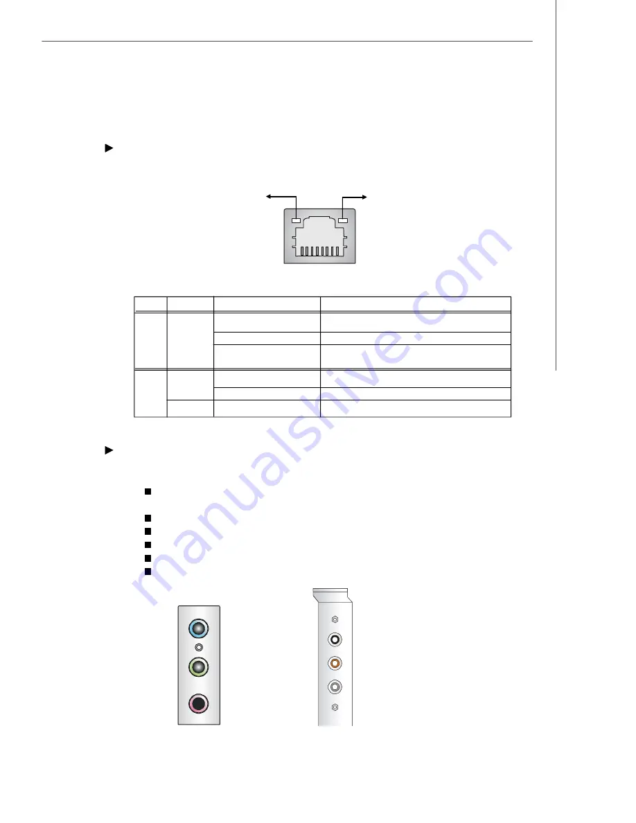
RJ-45 LAN Jack 

(optional)

The standard RJ-45 jack is for connection to single Local Area Network (LAN). You
can connect a network cable to it.


Audio Port  Connectors

These audio connectors are  used for audio devices. You can differentiate the color
of  the audio jacks for different  audio sound effects.

  Blue audio jack 

- Line In, is used for external CD player, tapeplayer or

other audio  devices.

  Green audio jack 

- Line Out, is a connector for speakers or headphones.

  Pink audio jack

 - Mic  In, is a connector for microphones.

  Black audio jack 

- Rear-Surround Out in 5.1/ 7.1 channel mode.

  Orange audio jack

 - Center/ Subwoofer Out in 5.1/ 7.1 channel mode.

  Gray audio jack 

- Side-Surround Out in 5.1/ 7.1 channel mode.

LED

Color

LED State

Condition

Off

LAN link is not established.

Left

Orange

On (steady state)

LAN link is established.

On (brighter & pulsing)

The computer is communicating with another
computer on the LAN.

Green

Off

10 Mbit/sec data rate is selected.

Right

On

100 Mbit/sec data rate is selected.

Orange

On

1000 Mbit/sec data rate is selected.

Link Indicator

8         1

Activity Indicator

RJ-45 LAN Jack

Line  Out

Line  In

M IC

Rear Out

Center  and  Subwoofer  Out

Side  Surround  Out

Back  Panel

Optional  Audio  Bracket

Summary of Contents for MS-7242

Page 1: ...i K9AGM Series MS 7242 V1 X Mainboard G52 72421X1...

Page 2: ...or other countries PS 2 and OS 2 are registered trademarks of International Business Machines Corporation Windows 95 98 2000 NT XP are registered trademarks of Microsoft Corporation Netware is a regi...

Page 3: ...ace the power cord such a way that people can not step on it Do not place anything over the power cord 8 Always Unplug the Power Cord before inserting any add on card or module 9 All cautions and warn...

Page 4: ...interference by one or more of the measures listed below Reorient or relocate the receiving antenna Increase the separation between the equipment and receiver Connect the equipment into an outlet on...

Page 5: ...v WEEE Waste Electrical and Electronic Equipment Statement...

Page 6: ...vi...

Page 7: ...vii...

Page 8: ...5 Memory 2 6 Memory Population Rules 2 6 Installing DDRII Modules 2 7 Back Panel 2 9 ATX 24 Pin Power Connector ATX1 2 10 ATX 12V Power Connector JPW1 2 10 Power Supply 2 10 Floppy Disk Drive Connect...

Page 9: ...s 3 9 Advanced Chipset Features 3 10 Integrated Peripherals 3 12 Power Management Features 3 14 PNP PCI Configurations 3 17 H W Monitor 3 18 Load Fail Safe Optimized Defaults 3 21 BIOS Setting Passwor...

Page 10: ...3 Before You Begin C 4 Basic Graphics Card Installation C 4 Installing a Graphics Card C 5 EnablingSURROUNDVIEWTM C 6 Frequently Asked Questions C 7 Setting Up Multiple Displays C 8 Using Multiple Di...

Page 11: ...board from MSI Based on the innovative ATI RS485 RS485C SB600 controllers for optimal system efficiency the K9AGM Series accommodates the latest AMD Sempron Athlon64 Athlon64 X2 AM2 processors in Sock...

Page 12: ...nal Supports PCI LAN Realtek RTL8100C 10 100 or RTL8110SB SC 10 100 1000 Fast Ethermet optional 1394 Optional Supports 2 IEEE1394 ports transfer rate is up to 400Mbps Controlled by VIA VT6307 VT6308 o...

Page 13: ...rd Pinheaders 3 USB 2 0 pinheaders 1 1394 pinheader optional 1 TV out pinheader optional 1 Audio header rear center side output Slots 1 PCI Express x16 slot 2 PCI slots 1 PCI Express x 1 slot Form Fac...

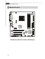
Page 14: ...1 SPDOUT1 optional J1394_1 optional JUSB3 JUSB2 JUSB1 JFP2 JBAT1 JCI1 SATA4 SATA2 SATA3 SATA1 JFP1 PCI _EX1 JCOM1 Top LAN Jack Bottom USB Ports Top 1394 Port Bottom USB Ports optional T Line In M Line...

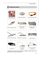
Page 15: ...oard MSI Driver Utility CD Back IO Shield 1394 Bracket Optional USB Bracket Optional Standard Cable for IDE Devices Standard Cable for Floppy Disk The pictures are for reference only Your packing cont...

Page 16: ...dures While doing the installation be careful in holding the components and follow the installation procedures For some components if you install in the wrong orientation the components will not work...

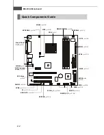
Page 17: ...DE1 p 2 11 ATX1 p 2 10 CPUFAN1 p 2 13 FDD1 p 2 11 JCOM1 p 2 17 J1394_1 p 2 13 PCI Express Slots p 2 21 PCI Slots p 2 21 JAUD1 p 2 14 JCD1 p 2 14 JFP1 p 2 16 JUSB1 2 3 p 2 18 SATA1 4 p 2 12 JCI1 p 2 14...

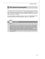
Page 18: ...power supply or unplug the power supply s power cord from the grounded outlet first to ensure the safety of CPU The mainboard supports AMD Sempron Athlon64 Athlon64 X2 AM2 processors in Socket 940 Whe...

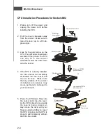
Page 19: ...embedded into the socket and can not be seen Please note that any violation of the correct installation procedures may cause permanent damages to your mainboard 5 Press the CPU down firmly into the s...

Page 20: ...he appearance of your mainboard may vary depending on the model you purchased Important 2 Then press down the other end of the clip to fasten the cooling set on the top of the retention mechanism Loca...

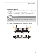
Page 21: ...memory interface Each DIMM slot supports up to a maximum size of 2GB Users can install either single or double sided modules depending on their needs Important Make sure that you install memory modul...

Page 22: ...Insert the memory module vertically into the DIMM slot Then push it in until the golden finger on the memory module is deeply inserted in the DIMM slot 3 The plastic clip at each side of the DIMM slot...

Page 23: ...device To connect an LCD monitor simply plug your monitor cable into the DVI connector and make sure that the other end of the cable is properly connected to your monitor refer to your monitor manual...

Page 24: ...s a connector for microphones Black audio jack Rear Surround Out in 5 1 7 1 channel mode Orange audio jack Center Subwoofer Out in 5 1 7 1 channel mode Gray audio jack Side Surround Out in 5 1 7 1 cha...

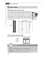
Page 25: ...12V 4 12V JPW1 Pin Definition pin 12 pin 13 JPW1 1 3 4 2 1 ATX1 12 24 13 ATX 24 Pin Power Connector ATX1 This connector allows you to connect an ATX 24 pin power supply To connect the ATX 24 pin power...

Page 26: ...isk drives CD ROM and other IDE devices The Ultra ATA133 interface boosts data transfer rates between the computer and the hard drive up to 133 megabytes MB per second The new interface is one third f...

Page 27: ...ATA cable Serial ATA Connectors SATA1 SATA4 SATA1 SATA4 are high speed SATA II interface ports and support SATA II data rates of 300MB s Each SATA II connector can connect to 1 hard disk device and is...

Page 28: ...specially designed fan with speed sensor to take advantage of the CPU fan control Important Please refer to the recommended CPU fans at Intel AMD official website or consult the vendors for proper CP...

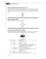
Page 29: ...ing you must enter the BIOS utility and clear the record JCI1 2 GND CINTRU 1 JCD1 GND R L JAUD1 1 2 9 10 Pin Definition PIN SIGNAL DESCRIPTION 1 PORT 1L Analog Port 1 Left channel 2 GND Ground 3 PORT...

Page 30: ...for you to attach an external Audio Out bracket optional The Audio Out bracket offers three audio out jacks Select the appropriate one to connect to the proper speaker Pin Definition PIN SIGNAL PIN SI...

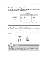
Page 31: ...ull down to GND 9 RSVD_DNU Reserved Donot use JFP1 Pin Definition 2 1 10 9 JFP1 HDD LED Reset Switch Power LED Power Switch Front Panel Connectors JFP1 JFP2 The mainboard provides two front panel conn...

Page 32: ...t sends receives 16 bytes FIFOs You can attach a serial mouse or other serial devices directly to it PIN SIGNAL DESCRIPTION 1 DCD Data Carry Detect 2 SIN Serial In orReceive Data 3 SOUT Serial Out orT...

Page 33: ...te up to a maximum throughput of 480Mbps which is 40 times faster than USB 1 1 and is ideal for connecting high speed USB interface peripherals such as USB HDD digital cameras MP3 players printers mod...

Page 34: ...one to connect to the standard television or the HDTV High Definition TeleVision and it will be able to display PC s information TV Out Bracket Optional Connected to JTV1 TV Out Connector S Video TV...

Page 35: ...OS RAM the system can automatically boot OS every time it is turned on If you want to clear the system configuration set the JBAT1 Clear CMOS Jumper to clear data Important You can clear CMOS by short...

Page 36: ...Moreover PCI Express architecture provides a high performance graphics infrastructure for Desktop Platforms doubling the capability of existing AGP 8x de signs with transfer rates of 4 0 GB s over a P...

Page 37: ...IOS Setup program and allows you to configure the system for optimum use You may need to run the Setup program when An error message appears on the screen during the system booting up and requests you...

Page 38: ...NIX 2nd 5th digit refers to the model number 6th digit refers to the chipset as I Intel N nVidia A ATI and V VIA 7th 8th digit refers to the customer as MS all standard customers V1 0 refers to the BI...

Page 39: ...Then you can use the control keys to enter values and move from field to field within a sub menu If you want to return to the main menu just press the Esc General Help F1 The BIOS setup program provid...

Page 40: ...hipset Features Use this menu to change the values in the chipset registers and optimize your system s performance Integrated Peripherals Use this menu to specify your settings for integrated peripher...

Page 41: ...nce Load Optimized Defaults Use this menu to load the default values set by the mainboard manufacturer specifi cally for optimal performance of the mainboard BIOS Setting Password Use this menu to set...

Page 42: ...rd Fourth IDE Master Slave Type Press PgUp or PgDn to select Manual None or Auto type Note that the specifications of your drive must match with the drive table The hard disk will not work properly if...

Page 43: ...ntrols the DMA Direct Memory Access mode Hard Disk S M A R T This allows you to activate the S M A R T Self Monitoring Analysis Reporting Technology capability for the hard disks S M A R T is a utilit...

Page 44: ...2 This allows you to run the OS 2 operating system with DRAM larger than 64MB IOAPIC Function This field is used to enable or disable the APIC Advanced Programmable Interrupt Controller Due to compli...

Page 45: ...ion to Yes allows the system to try to boot from other device if the system fails to boot from the first second third boot device Hard Disk Drives Removable Drives CD DVD Drives These settings allow u...

Page 46: ...ncrease system performance while bigger clocks provide more stable system performance RAS Precharge Time Trp When the DRAM Timing is set to Manual this field is adjustable This setting controls the nu...

Page 47: ...lti monitor support for computers that use a PCI Express based graphics card in con junction with ATI integrated graphics processors IGPs Display Device Select Use the field to select the type of devi...

Page 48: ...s DOS and SCO Unix Set to Disabled only if you want to use any USB device other than the USB mouse Onboard LAN Controller This setting controls the onboard LAN controller LAN Option ROM This setting e...

Page 49: ...on the PCI local bus has bus mastering capability OnChip SATA Controller This setting controls the onchip SATA controller OnChip SATA Type This setting specifies the function type of SATA devices I O...

Page 50: ...Setting options S1 POS The S1 sleep mode is a low power state In this state no system context is lost CPU or chipset and hardware main tains all system context S3 STR The S3 sleep mode is a lower pow...

Page 51: ...before power failure or interrupt occurred Wake Up Event Setup Resume From S3 by USB Device The item allows the activity of the USB device to wake up the system from S3 Suspend to RAM sleep state Res...

Page 52: ...wer Management Event from PCI device Resume by PCIE Device When setting to Enabled this setting allows your system to be awakened from the power saving modes through any PME Power Management Event fro...

Page 53: ...raphics adapter PCI Latency Timer This item controls how long each PCI device can hold the bus before another takes over When set to higher values every PCI device can conduct transactions for a longe...

Page 54: ...ve the setting at Disabled for optimal system stability and performance But if you are plagued by EMI select the value of Spread Spectrum for EMI reduction 2 The greater the Spread Spectrum value is t...

Page 55: ...ecially desiged for AMD Athlon processor which provides a CPU temperature detecting function to prevent your CPU s from overheading due to the heavy working loading CPU FAN PIN Select Be sure to selec...

Page 56: ...3 20 MS 7242 Mainboard PC Health Status These items display the current status of all of the monitored hardware devices components such as CPU voltages temperatures and all fans speeds...

Page 57: ...specifically for optimal performance of the mainboard The Fail Safe Defaults are the default values set by the BIOS vendor for stable system performance When you select Load Fail Safe Defaults a messa...

Page 58: ...d and press Enter You may also press Esc to abort the selection and not enter a password To clear a set password just press Enter when you are prompted to enter the password A message will show up con...

Page 59: ...83 Audio Appendix A The Realtek ALC883 provides 10 channel DAC that si multaneously supports 7 1 sound playback and 2 chan nels of independent stereo sound output multiple streaming through the Front...

Page 60: ...Windows XP you must install Windows XP Service Pack1 or later before installing the driver The following illustrations are based on Windows XP environment and could look slightly different if you ins...

Page 61: ...A 3 Realtek ALC883 Audio 3 Click Next to install the Realtek High Definition Audio Driver 4 The installation begins Click here...

Page 62: ...o use the 2 4 6 or 8 channel audio feature now Click the audio icon from the system tray at the lower right corner of the screen to activate the HD Audio Configuration It is also available to enable t...

Page 63: ...nt You may choose the provided sound effects and the equalizer will adjust automatically If you like you may also load an equalizer setting or make an new equalizer setting to save as an new one by us...

Page 64: ...without losing the settings Load Whenever you would like to use preload settings simply click this the whole list will be shown for your selection Delete To delete the pre saved settings which are cr...

Page 65: ...Pop Live Club Rock shown on the page to pull down the arrow in Others you will find more optimized settings available to you Karaoke Mode Karaoke mode brings Karaoke fun back home Simply using the mus...

Page 66: ...ectively from the indicated real panel or front panel This feature is very helpful when 2 people are using the same computer together for different purposes Click the button and the Mixer ToolBox menu...

Page 67: ...from the rear panel which is the default setting Then you must to select the Realtek HD Audio front output from the scroll list first and use a different program to play the second audio source for e...

Page 68: ...single or multiple volume controls or to completely mute sound output Tool Show the following volume controls This is to let you freely decide which volume control items to be displayed Advanced cont...

Page 69: ...is is to let you freely decide which volume control items to be displayed Enable recording multi streaming Tool Mute Important ALC883 allows you to record the CD Line Mic and Stereo Mix channels simul...

Page 70: ...H Speaker for 5 1 Speaker Output e 8CH Speaker for 7 1 Speaker Output Speaker Configuration 1 Plug the speakers in the corresponding jack 2 Dialogue connected device will pop up for your selection Ple...

Page 71: ...ks Please check if front jacks on your system are so called AC 97 jacks If so please check this item to disable front panel jack detection Mute rear panel output when front headphone plugged in Enable...

Page 72: ...the signal from degrading when it is converted to analog Output Sampling Rate 44 1KHz This is recommend while playing CD 48KHz This is recommended while playing DVD or Dolby 96KHz This is recommended...

Page 73: ...up and make testing sound If any speaker fails to make sound then check whether the cable is inserted firmly to the connector or replace the bad speakers with good ones Or you may click the auto test...

Page 74: ...rom being recorded by mi crophone together with your sound For example you might have chance to use VOIP function through Internet with your friends The voice of your friend will come out from speaker...

Page 75: ...883 Audio 3D Audio Demo In this tab you may adjust your 3D positional audio before playing 3D audio applica tions like gaming You may also select different environment to choose the most suitable envi...

Page 76: ...Audio Controller Audio Codec You may also select the language of this utility by choosing from the Language list Also there is a selection Show icon in system tray Switch it on and an icon will show i...

Page 77: ...re utility n 2 Channel Mode for Stereo Speaker Output Refer to the following diagram and caption for the function of each phone jack on the back panel when 2 Channel Mode is selected Back Panel 3 1 2...

Page 78: ...ut connector and two speakers to the real chan nel Line Out connector 1 Line In 2 Line Out Front channels 3 MIC 4 Line Out Rear channels 5 Line Out Center and Subwoofer channel but no functioning in t...

Page 79: ...nector two speakers to the rear channel and two speakers to the cen ter subwoofer channel Line Out connectors 6 Channel Analog Audio Output 1 Line In 2 Line Out Front channels 3 MIC 4 Line Out Rear ch...

Page 80: ...to the rear channel two speakers to the center subwoofer channel Line Out connectors and two speakers to the side channel Line Out connectors 8 Channel Analog Audio Output 1 Line Out Side channels 2...

Page 81: ...cket before you can get access to the TV out function Follow the proce dures described later to set up the TV Out bracket and configure the display settings Note that the TV Out bracket works with the...

Page 82: ...ead to the malfunction of the TVs Installing the TV Out Bracket 1 Take out the TV Out bracket 2 Locate the TV out connector JTV1 on the mainboard 3 Connect the TV Out bracket to the connector Align th...

Page 83: ...g TV Out Function Connecting S Video HDTV Cables 1 Connect one end of the S Video cable to the TV Out S connector Connecting S Video cable 2 Connect the other end of the S Video cable to the TV S Vide...

Page 84: ...he other end of the HDTV cable to the HDTV 1 Connect one end of the HDTV cable to the TV Out C connectors The HDTV cable usually comes with three connecotrs on both ends Green HDTV cable Blue Red Conn...

Page 85: ...play Select item of Advance Chipset Features for details To enable the TV Out function follow this procedure 2 The setup screen appears Select Basic Easy Setup Wizards and Quick Set tings to open the...

Page 86: ...ainboard 3 Select Displays Manager in the left control pane 4 Select the display that you would like to enable Right click the mouse and select the desired desktop mode from the popup menu Then click...

Page 87: ...B 7 Using TV Out Function 5 Finally click Yes to complete the configuration...

Page 88: ...integrated feature sup ported by the onboard ATI northbridge chipset It pro vides the power and convenience of multi adapter multi monitor support for computers that use an PCI Express based graphics...

Page 89: ...d create a document on yet another SURROUNDVIEW is also ideal for an office environment For example a brokerage can monitor trades place orders and sell each on a different display When the home offic...

Page 90: ...aphics cards subject to change without notice l RADEON X300 series l RADEON X600 series l RADEON X700 series l RADEON X800 series l Or more advanced series Expansion Slot l PCIe TM x 16 Operating Syst...

Page 91: ...tegrated graphics processor will have separate drivers from your PCIe graphics card Do not uninstall the drivers for your IGP Before You Begin Before you begin installing your graphics card please do...

Page 92: ...r computer If you have properly installed your graphics card operating system messages will appear once the boot procedure is finished Your monitor will be running in a basic video mode Higher refresh...

Page 93: ...the arrow keys to navigate to VGA Share Memory Size The default value Recommended refers to a minimum size of 64MB and up Users may leave the value to Recommended or set it to 64MB or higher 4 Use the...

Page 94: ...SURROUNDVIEW Can SURROUNDVIEW run with other manufacturers graphics cards No only the ATI graphics cards noted in System Requirements will support SURROUNDVIEW If the integrated graphics processor IGP...

Page 95: ...ctions mode one from the TV out and two from the graphics card one from the IGP and two from the graphics card two from the IGP and one from the graphics card u To connect your monitors 1 Power off yo...

Page 96: ...y icon and choose Attached if necessary 8 Set the Screen Resolution and Color Quality as appropriate for the sec ond monitor Click Apply or OK to apply these new values u Refer to your Windows online...

Page 97: ...1 Install the TV out bracket to the mainboard 2 Connect the TV to the TV out bracket 3 Power on the computer Be sure you had install the ATi System Drivers already if not please install it 4 Click the...

Page 98: ...eens at the same time u To enable SURROUNDVIEW for business applications 1 Right click a clear area of your desktop click Properties click the Settings tab and then click the Identify button to displa...

Page 99: ...inboard 3 Open your Web browser and then drag it to monitor 2 Web browser displayed on monitor 2 4 Launch another instance of your Web browser and then drag it to monitor 3 Another Web browser display...

Page 100: ...screen and windowed mode press Alt Enter or in the Views menu click Full Screen Your displays will look like the following Initial Start Up Screen for Microsoft Flight Simulator u Monitor 2 v Monitor...

Page 101: ...2 running Important 1 When moving a 3D window you may see some hesitation when crossing the boundary to a secondary display After you move the 3D window to the secondary display that scene will be dis...

Page 102: ...C 15 ATI SURROUNDVIEWTM 4 From the Views menu create another new window and then drag it to monitor 3 Microsoft Flight Simulator using all three monitors...

Reviews: