background image

D-11

Dual  Core  Center

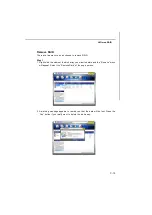
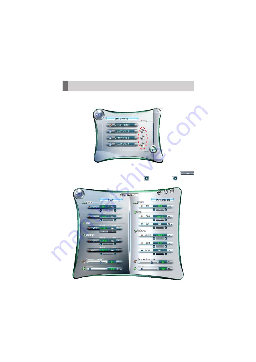
User Profile

In the 

User Profile 

sub-menu, click the setting button that besides the user profile

bar, and the  next screen will appear.

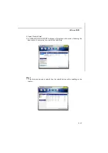
Here you can define the clock/ fan speed/ voltage by your need, click the
button to choose a value quickly, or click the plus        / minus sign        button to
increase/  decrease  the value.

Summary of Contents for MS-7375

Page 1: ...i K9N2 Diamond Series MS 7375 v1 X Mainboard G52 73751X1...

Page 2: ...of Intel Corporation PS 2 and OS 2 are registered trademarks of International Business Machines Corporation Windows 95 98 2000 NT XP are registered trademarks of Microsoft Corporation Netware is a re...

Page 3: ...ace the power cord such a way that people can not step on it Do not place anything over the power cord 8 Always Unplug the Power Cord before inserting any add on card or module 9 All cautions and warn...

Page 4: ...interference by one or more of the measures listed below Reorient or relocate the receiving antenna Increase the separation between the equipment and receiver Connect the equipment into an outlet on...

Page 5: ...v WEEE Waste Electrical and Electronic Equipment Statement...

Page 6: ...vi...

Page 7: ...vii...

Page 8: ...Quick Components Guide 2 2 CPU Central Processing Unit 2 3 Memory 2 6 Power Supply 2 8 Back Panel 2 10 Connectors 2 11 Button 2 17 Slots 2 18 Chapter 3 BIOS Setup 3 1 Entering Setup 3 2 The Main Menu...

Page 9: ...theNVMediaShield Software B 11 Appendix C JMicron RAID Introduction C 1 Introduction C 2 JMicron RAID BIOS Utility C 3 Installing Driver C 11 JMicron Raid Configurer C 13 Appendix D Dual Core Center...

Page 10: ...X ATX mainboard The K9N2 Diamond Series mainboards are based on NVIDIA nForce780a SLI single chipset for optimal system efficiency Designed to fit the advanced AMD Phenom Athlon Sempron series in Sock...

Page 11: ...ible components please visit http global msi com tw index php func testreport LAN Supports 10 100 1000 Fast Ethernet Dual LAN by Realtek 8211BL 8111C 1394 Transfer rate is up to 400Mbps Controlled by...

Page 12: ...pinheader 1 TPM Module pinheader 1 Chassis Intrusion pinheader TPM Supports TPM Slots 3 PCI Express x16 slots compatible with PCIE 2 0 specification a support 3 Way SLI these three PCIE x16 lanes wil...

Page 13: ...4_1 JFP1 JFP2 FDD 1 SYSFAN4 SYSFAN2 SYSFAN1 CPUFAN JPW1 JUSB3 nFroce 200 JUSB2 JUSB1 JMB363 RTL8211BL VIA VT6308P I O Chip RTL8111C RESET POWER CLR_CMOS JCI1 SATA5 SATA1 2 SATA6 SATA3 4 SYSFAN3 IDE1 A...

Page 14: ...er Utility CD The pictures are for reference only and may vary from the packing contents of the product you purchased Floppy Cable IDE Cable Back IO Shield SATA Cable 3 Way SLI bridge cables 1 long 2...

Page 15: ...dures While doing the installation be careful in holding the components and follow the installation procedures For some components if you install in the wrong orientation the components will not work...

Page 16: ...Slots p 2 24 JUSB1 3 p 2 14 SATA p 2 12 CPUFAN p 2 13 PCI Express slots p 2 18 CPU p 2 3 J1394_1 p 2 15 Quick Components Guide SYSFAN3 p 2 13 JFP2 p 2 16 JCI1 p 2 14 FDD1 p 2 12 JTPM1 p 2 15 JCOM1 p 2...

Page 17: ...damage the CPU and system Always make sure the cooling fan can work properly to protect the CPU from overheating Make sure that you apply an even layer of thermal paste or thermal tape between the CP...

Page 18: ...ectly installed the pins should be completely embedded into the socket and can not be seen Please note that any violation of the correct installation procedures may cause permanent damages to your mai...

Page 19: ...he clip to fasten the cooling set on the top of the retention mechanism Locate the Fix Lever and lift up it 1 Position the cooling set onto the re tention mechanism Hook one end of the clip to hook fi...

Page 20: ...he following illustrations explain the population rules for Dual Channel mode 64x2 128 pin 56x2 112 pin Empty Installed Important DDR2 memory modules are not interchangeable with DDR and the DDR2 stan...

Page 21: ...t in until the golden finger on the memory module is deeply inserted in the DIMM slot The plastic clip at each side of the DIMM slot will automatically close when the memory module is properly seated...

Page 22: ...he power supply is inserted in the proper orientation and the pins are aligned Then push down the power supply firmly into the connector You may use the 20 pin ATX power supply as you like If you d li...

Page 23: ...ions might cause system chipset unable to boot Please follow the following solution to avoid this situation Unplug the AC power cable shown in figure 1 or unplug all power connectors on the mianboard...

Page 24: ...dard RJ 45 LAN jack is for connection to the Local Area Network LAN You can connect a network cable to it USB Port The USB Universal Serial Bus port is for attaching USB devices such as keyboard mouse...

Page 25: ...n also connect a Master and a Slave drive IDE Connector IDE1 IDE2 This connector supports IDE hard disk drives optical disk drives and other IDE devices Important If you install two IDE devices on the...

Page 26: ...nect to one Serial ATA device Floppy Disk Drive Connector FDD1 This connector supports 360KB 720KB 1 2MB 1 44MB or 2 88MB floppy disk drive FDD1 SATA1 2 SATA3 4 SATA5 SATA6 Important 1 SATA5 SATA6 sup...

Page 27: ...positive and should be connected to the 12V the black wire is Ground and should be connected to GND If the mainboard has a System Hardware Monitor chipset on board you must use a specially designed fa...

Page 28: ...esign Guide is ideal for con necting high speed USB interface peripherals such as USB HDD digital cameras MP3 players printers modems and the like JUSB1 2 3 USB 2 0 Bracket 1 2 9 10 Chassis Intrusion...

Page 29: ...JTPM1 This connector connects to a TPM Trusted Platform Module module optional Please refer to the TPM security platform manual for more details and usages Pin Signal Description Pin Signal Descriptio...

Page 30: ...with Intel Front Panel I O Connectivity Design Guide JFP2 PIN SIGNAL DESCRIPTION 1 HD_LED Hard disk LED pull up 2 FPPWR SLP MSG LED pull up 3 HD_LED Hard disk active LED 4 FPPWR SLP MSG LED pull up 5...

Page 31: ...guration data With the CMOS RAM the system can automati cally boot OS every time it is turned on If you want to clear the system configuration use the button to clear data Press the button to clear th...

Page 32: ...fer to the keys below a support 3 Way SLI these three PCIE x16 lanes will configure to x16 x8 x8 b if you intend to install two expansion cards please install one into the mazarine slot and one into t...

Page 33: ...le Important Before you configure the 3 Way SLI platform hardware please make sure that 1 The three graphics cards have to support 3 Way SLI technology and they are of the same brand and specification...

Page 34: ...ables are required to connect the golden fingers on the top of these three graphics cards fig 1 Please note that although you have installed three graphics cards only the video outputs on the first ca...

Page 35: ...to use 2 way SLI you must install the two graphics cards in one mazarine PCIE x16 slot PCI_E2 and the first blue PCIE x16 slot PCI_E3 Then connect two graphics cards together using the 2 SLI bridge sh...

Page 36: ...Go to 3D Settings Set SLI configuration and check Enable SLI technol ogy recommended Then press Apply concerning the details of multi GPU settings please refer to your graphics card manual Important I...

Page 37: ...orce Boost is enabled The chipset will share the rendering load with the graphic card and boost the performance of the graphic card Click on the Hybrid Icon in the System tray can select the Hybird mo...

Page 38: ...R Q are hardware lines over which devices can send interrupt signals to the microprocessor The PCI IRQ pins are typically connected to the PCI bus pins as follows Order 1 Order 2 Order 3 Order 4 PCI...

Page 39: ...to configure the system for optimum use You may need to run the Setup program when An error message appears on the screen during the system booting up and requests you to run SETUP You want to change...

Page 40: ...e model number 6th digit refers to the chipset as I Intel N nVidia and V VIA 7th 8th digit refers to the customer as MS all standard customers V1 0 refers to the BIOS version 021308 refers to the date...

Page 41: ...to enter values and move from field to field within a sub menu If you want to return to the main menu just press the Esc General Help F1 The BIOS setup program provides a General Help screen You can...

Page 42: ...ings for integrated peripherals Power Management Setup Use this menu to specify your settings for power management H W Monitor This entry shows your PC health status BIOS Setting Password Use this men...

Page 43: ...nce Load Optimized Defaults Use this menu to load the default values set by the mainboard manufacturer specifi cally for optimal performance of the mainboard Save Exit Setup Save changes to CMOS and e...

Page 44: ...Read only month The month from Jan through Dec date The date from 1 to 31 can be keyed by numeric function keys year The year can be adjusted by users Time HH MM SS This allows you to set the system t...

Page 45: ...to move data from a hard disk that is going to fail to a safe place before the hard disk becomes offline Floppy Drive A This item allows you to set the type of floppy drives installed Available option...

Page 46: ...red on Setting to Off will allow users to use the arrow keys on the numeric keypad IOAPIC Function This field is used to enable or disable the APIC Advanced Programmable Interrupt Controller Due to co...

Page 47: ...M2 CPU only This item is used to enable or disable the AMD SVM Secure Virtual Machine mode Chipset Feature Press Enter to enter the sub menu and the following screen appears HPET The HPET High Precisi...

Page 48: ...load the disk operating system Boot From Other Device Setting the option to Yes allows the system to try to boot from other device if the system fails to boot from the 1st 2nd 3rd boot device Trusted...

Page 49: ...invoke the Boot ROM of the LAN controller Onboard 2nd LAN Controller This item is used to enable disable the onboard 2nd LAN controller LAN Option ROM This item is used to decide whether to invoke the...

Page 50: ...used PCI busmastering for reading writing to IDE drives On Chip SATA Controller This item allows you to enable disable the SATA controller RAID mode select Setting this option to RAID activates the f...

Page 51: ...S1 The S1 sleep mode is a low power state In this state no system context is lost CPU or chipset and hardware main tains all system context S3 The S3 sleep mode is a lower power state where the in fo...

Page 52: ...the following sub menu appears Wake Up Event By Setting to BIOS activates the following fields and use the following fields to set the wake up events Setting to OS the wake up events will be defined b...

Page 53: ...PCI Express device Resume By Onbaord LAN When set to Enabled the feature allows your system to be awakened from the power saving modes through any event on LAN device Resume By RTC Alarm The field is...

Page 54: ...he current CPU fan temperature reaches to the target value the smart fan function will be activated It provides several sections to speed up for cooling down automaticlly CPU Min FAN Speed When you se...

Page 55: ...s Esc to abort the selection and not enter a password To clear a set password just press Enter when you are prompted to enter the password A message will show up confirming the password will be disabl...

Page 56: ...detects CPU is running programs it will speed up CPU automatically to make the program run smoothly and faster When the CPU is temporarily suspending or staying in the low load balance it will restore...

Page 57: ...sically it is still risky We suggest user to make sure that your CPU can afford to overclocking regularly first If you find the PC appears to be unstable or reboot incidentally it s better to disable...

Page 58: ...he following related items manually Bank Interleave This field selects 2 bank or 4 bank interleave for the installed SDRAM Disable the function if 16MB SDRAM is installed 1T 2T Memory Timing When the...

Page 59: ...equency MHz This item shows the adjusted DRAM frequency Read only HT Configuration Press Enter to enter the sub menu and the following screen appears SB to AM2 FreqAuto Selecting Disabled allows users...

Page 60: ...trum value please consult your local EMI regulation 3 Remember to disable Spread Spectrum if you are overclocking because even a slight jitter can introduce a temporary boost in clock speed which may...

Page 61: ...s item and press Enter to save any changes you have made to your current settings Load Settings 1 2 Select this item and press Enter to load settings from the store USER SETTINGS PDF created with pdfF...

Page 62: ...l SPDIF audio effect and allows users to attach 2 4 6 or 8 speakers for better surround sound effect This manual will tell you about the specifications of the card how to install it to a mainboard how...

Page 63: ...ets pre configurable modes simulating various acoustic environments Optimized settings for headphones stereo 4 1 5 1 6 1 or 7 1 speakers Creative Multi Speaker Surround CMSS technology transforms all...

Page 64: ...r Centre Subwoofer or Headphone out Line In Microphone In S PDIF In and S PDIF Out Auxiliary Audio in Works with the Following Standards Windows XP SP2 and Vista Sound Blaster MIDI and General MIDI Mi...

Page 65: ...e Audio Card to the PCI E slot and secure the card bracket with a screw 6 Replace and secure the case Reconnect the power cord to the computer Select Audio Controller If your mainboard integrates audi...

Page 66: ...els Connecting the Speakers When you have set the Multi Channel Audio Function mode properly in the software utility connect your speakers to the correct jacks in accordance with the setting in softwa...

Page 67: ...put Refer to the diagram and caption for the function of each jack on the back panel when 8 Channel Mode is selected 6 Channel Analog Audio Output 1 S PDIF Out Optical 2 MIC Line In 3 Line Out Front c...

Page 68: ...ws XP VISTA Install Windows XP Service Pack 1 for Windows XP before installing the driver The following illustrations are based on Windows XP environment and could look slightly different if you insta...

Page 69: ...e that you need from the list 3 Select your region from the list 5 On the next page click Install to start the installation and follow the setup instruc tions to complete 6 Finally you have to restart...

Page 70: ...er right corner of the screen to activate the Sound Blaster X Fi Xtreme Audio Applications simply click on each icon to enter the configuration screen Or you can move the mouse cursor to the top of sc...

Page 71: ...cher consists of various tabs such as Programs Product Settings Product Support and Companion Products In each tab you can access different applications called Tasks For more information and usage det...

Page 72: ...uter Audition presets on your computer The virtual keyboard in SFBM allows you to audition presets quickly on your computer You can also audition presets from an external MIDI device such as a MIDI ke...

Page 73: ...d audio CDs with a CD writer and print your own CD covers Organize your digital music collection with a powerful easy to use music library Search for tracks with an advanced Find feature that searches...

Page 74: ...e or speaker volume bass and treble levels Adjust volume mixer settings Configure playback settings for your speakers or headphones Adjust equalizer settings Enable environment effects Enable multicha...

Page 75: ...eaker volume Default button Click on this button to revert all the settings in Entertain ment Mode to the default Main Display button Click on this button to revert to the main display This button dis...

Page 76: ...eakers to use select the speakers type that you connected Testing your speakers click on the Channel or Noise button to test the speakers For more information and usage details on MIXER refer to its o...

Page 77: ...the CMSS 3D configuration mean by check the Enable X Fi CMSS 3D Virtual item Then you can select CMSS for multichannel audio enhancement on 4 4 1 5 1 6 1 or 7 1 speaker systems X Fi CMSS 3D Click on t...

Page 78: ...used by the world s lead ing businesses to the common PC desktop This tech nology uses multiple drives to either increase total disk space or to offer data protection For all levels RAID techniques o...

Page 79: ...ce RAID 0 Non critical data requiring high performance High data throughput No fault tolerance multiple None RAID 1 Small databases or any other small capacity environment requiring fault tolerance 10...

Page 80: ...y 3 Boot from the Windows CD use the floppy disk that has the RAID driver to copy and install the nForce RAID software Check p B 7 for details 4 Initialize the NVRAID Array Disks Setting Up the NVRAID...

Page 81: ...hat the port is associated with The 2nd digit defines the channel In the example above 1 0 means the hard drive is attached to Adapter 1 Channel 0 The following is a list of all possible combinations...

Page 82: ...KB but the values can be between 4 KB and 128 KB Assigning the Disks The disks that you enabled from the RAID Config BIOS setup page appear in the Free Disks block These are the drives that are availa...

Page 83: ...up 3 Use the arrow keys to select the array that you want to set up then press Enter The Array Detail window appears 4 If you want to mark this disk as empty and wipe out all its contents then press C...

Page 84: ...y drive until the blue screen portion of Win dows XP installation is completed then take out the floppy 9 Follow the instructions on how to install Windows XP After Windows XP is completely installed...

Page 85: ...pplication and install the RAID software which will upgrade the Windows SATA driver and install the RAID software 1 Start the NVIDIA nForce Drivers installation program to open the NVIDIA Windows nFor...

Page 86: ...ontrol Panel then open the Administrative Tools folder and double click on Computer Management 2 Click Disk Management under the Storage section The Initialize and Convert Disk Wizards appears 3 Click...

Page 87: ...h The Computer Management window appears The actual disks listed will depend on your system and the unallocated partition is the total combined storage of two hard disks You must format the unallocate...

Page 88: ...g the NVMediaShield Software Accessing the Storage Page To access the NVIDIA Control Panel Storage page 1 Click Star Programs NVIDIA Corporation NVIDIA Control Panel Storage 2 The NVIDIA Control Panel...

Page 89: ...estoring data to a hard drive from other drives in the array For example if you have a three disk RAID 5 array and one of the drives fails you will need to replace the failed drive with a new one and...

Page 90: ...or example during a system crash where a RAID mirrored drive is broken The dedicated disk can be used only by the array that it is assigned to and not by any other array unlike a free disk which can b...

Page 91: ...rray type to another General Migrating Requirements The new array capacity must be equal to or greater than the previous array For example it is possible to migrate from a RAID 1 array to a RAID 0 arr...

Page 92: ...From To New Array Disk Requirements RAID 0 m n Number of disks in the new array must be greater than the original array RAID 1 m 2 n 1 RAID 1 array must include two disks converted from a one disk RAI...

Page 93: ...Array and Migrate Array Wizard from the list of links in the Related tasks section of the side menu Instructions Click View Storage Configuration to open the associated page The View Storage Configura...

Page 94: ...Appendix C This appendix will assist users in configuring and enabling RAID functionality on platforms The JMicron RAID solution supports RAID level 0 striping RAID level 1 mirroring RAID level 10 st...

Page 95: ...data redundancy by mirroring data between the hard drives and provides enhanced read performance RAID 10 Not one of the original RAID levels multiple RAID 1 mirrors are created and a RAID 0 stripe is...

Page 96: ...RAID set Delete RAID Disk Drive Delete a legacy RAID set Revert HDD to Non RAID Revert an existed RAID HDD to non RAID Solve Mirror Conflict Sovle a mirror conflict Rebuild Mirror Drive Rebuild data w...

Page 97: ...reate RAID Disk Drive Then press Enter 3 Choose a 0 Striped a 1 Mirror or a JBOD Concatenate combination set and then press Enter to go to the next step 2 Then in the Name field specify a RAID set nam...

Page 98: ...ction 5 Then select the block value stripe value for the RAID array by using the upper arrow or down arrow keys to scroll through the available values and pressing the Enter key to select and advance...

Page 99: ...field 7 The Creation field will display a message to ask you to confirm the creation Then press Y key to proceed with the RAID set creation 8 Then the following screen appears to indicate that the cre...

Page 100: ...et 1 Select Delete RAID Disk Drive Then press Enter 2 In the RAID Disk Driver List menu use Space key to select the RAID set you want to delete Then press Del key 3 Press Y to accept the deletion when...

Page 101: ...vert then click Enter key The following screen appears press Y key to remove any RAID structures from the drives Important 1 You will lose all data on the RAID drives and any internal RAID structures...

Page 102: ...you to set the source drive and rebuild the Mirror drive according to the contents of the source drive To solving a Mirror conflict Select Solving a Mirror Conflict and press Enter In the Hard Disk D...

Page 103: ...rm otherwise press N This option allows you to rebuild the Mirror drive later and synchronize the data between two hard disks To rebuild a Mirror drive Select Rebuild Mirror Drive and press Enter Usin...

Page 104: ...oller Press ENTER again to continue 8 You have successfully installed the JMicron RAID driver and Windows setup should continue 9 Leave the disk in the floppy drive until the system reboots itself Win...

Page 105: ...on JMicron JMB363 Drivers 4 The drivers will be automatically installed Confirming Windows Vista XP Driver Installation 1 From Windows Vista XP 2000 open the Control Panel from My Compu ter followed b...

Page 106: ...ting a RAID Array Rebuilding RAID Arrays Solving Mirror Conflict View RAID Array Configurations Left click the Show Disks button and the information of all hard disks will display on the right side of...

Page 107: ...eate RAID from Existing Disk You can combine the Existing Disk Source disk may content OS and Data with other HD must be larger than source Disk to be RAID The data on Source Disk will be reserved Aft...

Page 108: ...ID Way 1 1 Right click the name of the disk array you want to delete and the Remove menu will appear Select the Remove Raid of the pop up menu 2 A warning message appears to remind you that the data w...

Page 109: ...display on the screen following the de scription of every step to complete the deletion Rebuild RAID RAID 1 0 1 can be rebuilt while RAID 0 JBOD cannot be rebuilt There are two ways you can choose to...

Page 110: ...d Raid 3 A REBUILD RAID WIZARD dialogue will display on the screen following the description of every step to complete the rebuilding Way 2 1 If the disk array needs to rebuild then the rebuild button...

Page 111: ...D dialogue will display on the screen following the description of every step to complete the rebuilding Solve Mirror Conflict If the conflict occurs it will show the REBUILDING RAID WIZARD dialogue t...

Page 112: ...hard ware status of MSI Mainboard MSI Graphics card in windows such as CPU GPU clock voltage fan speed and temperature Before you install the Dual CoreCenter please make sure the system has meet the f...

Page 113: ...our mainboard path Utility MSI Utility Dual Core Center it will have an icon in the system tray a short cut icon on the desktop and a short cut path in your Start up menu You may double click on each...

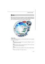
Page 114: ...us of the MSI mainboard would be available Introduction Click each button appearing above to enter sub menu to make further configuration or to execute the function M B Click MB button to read current...

Page 115: ...you can adjust and monitor the fan speeds of MB and graphics card Temperature In this sub menu you can monitor the temperatures of MB and graphics card User Profile In this sub menu you can set the v...

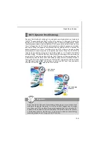
Page 116: ...e it will restore the default settings instead Usually the Dynamic Overclocking Technology will be powered only when users PC runs huge amount of data like 3D games or video process and the motherboar...

Page 117: ...hase power Through the Dual Channel PWM power loss can be reduced which allows CPU to receive higher power efficiency in higher loading condition In the Efficiency Monitor menu you can read the real t...

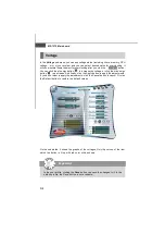
Page 118: ...rease the clock or click the minus sign button to decrease the clock And finally click the Apply button to apply the values adjusted If you do not want to apply the adjustments click the Cancel button...

Page 119: ...tage or click the minus sign button to decrease And finally click the Apply button to apply the adjustments If you do not want to apply the adjustments click the Cancel button to cancel Or click the D...

Page 120: ...ection or click the minus sign button to decrease Or click the Default button to restore the default values On the underside it shows the graphs of the fan speed Only the curves of the item which the...

Page 121: ...mperature In the Temperature sub menu you can see temperature status of your system On the underside it shows the graphs of the temperatures Only the curves of the item which the button is lit up with...

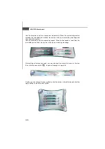
Page 122: ...click the setting button that besides the user profile bar and the next screen will appear Here you can define the clock fan speed voltage by your need click the button to choose a value quickly or c...

Page 123: ...draw bar to set the minimal fan speed When the fan speed is lower than the threshold you defined the system will pop up a warning message Finally you can choose the user profile by click the button i...

Reviews: