background image

A-7

Realtek  Audio

Raise  the  key

Lower   the  key

Remov e  the
human  voice

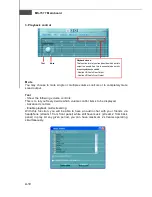
Frequently  Used  Equalizer Setting

Realtek recognizes the needs that you might have. By leveraging our long experience
at audio field, Realtek HD Audio Sound Manager provides you certain optimized equal-
izer settings  that are frequently used for your quick enjoyment.

[How to Use It]
Other than the buttons 

Pop


Live


Club

 & 

Rock

 shown on the page, to pull down

the arrow in 

Others

, you will find more optimized settings available to you.

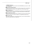
Karaoke  M ode

Karaoke mode brings Karaoke fun back home. Simply using the music you  usually
play, Karaoke mode can help you eliminate the vocal of the song or adjust the key to
accommodate your  range.
1.Vocal Cancellation: Single click on 

Voice Cancellation

, the vocal of the song would

   be eliminated, while the background music is still in place, and you can be that
   singer!
2.Key Adjustment: Using 

Up / Down Arrow

 to find a key which better fits your vocal

   range.

Summary of Contents for MS-7577

Page 1: ...790FX GD70 Series MS 7577 v1 X Mainboard G52 75771X1...

Page 2: ...rademarks of Intel Corporation PS 2 and OS 2 are registered trademarks of International Business Machines Corporation Windows NT XP Vista are registered trademarks of Microsoft Corporation Netware is...

Page 3: ...ace the power cord such a way that people can not step on it Do not place anything over the power cord 8 Always Unplug the Power Cord before inserting any add on card or module 9 All cautions and warn...

Page 4: ...interference by one or more of the measures listed below Reorient or relocate the receiving antenna Increase the separation between the equipment and receiver Connect the equipment into an outlet on...

Page 5: ...v WEEE Waste Electrical and Electronic Equipment Statement...

Page 6: ...vi...

Page 7: ...vii...

Page 8: ...Chapter 2 Hardware Setup 2 1 Quick Components Guide 2 2 CPU Central Processing Unit 2 3 Memory 2 6 Power Supply 2 8 Back Panel 2 9 Connectors 2 11 Button 2 19 Slots 2 22 LED Status Indicators 2 26 Ch...

Page 9: ...Software Configuration A 4 Hardware Setup A 19 Appendix B Overclocking Center B 1 Activating Overclocking Center B 2 System Info B 3 DOT B 5 Appendix C SB750 SATA RAID C 1 RAID Configuration C 2 Appen...

Page 10: ...v1 X ATX motherboard The 790FX GD70 Series motherboards are based on AMD 790FX SB750 chipset for optimal system efficiency Designed to fit the advanced AMD Phenom II X4 X3 and Athlon X4 X3 X2 AM3 pro...

Page 11: ...nents please visit http global msi com tw index php func testreport LAN Supports Dual Gigabit LAN by Realtek RTL8111DL IEEE 1394 optional Chip integrated by VIA VT6315N Supports 2 IEEE1394 ports rear...

Page 12: ...IEEE 1394 pinheader optional 1 COM port pinheader 1 CD in pinheader 1 TPM Module pinheader 1 Chassis Intrusion pinheader 1 Front Panel Audio pinheader 1 S PDIF out pinheader 1 Debug LED Slots 4 PCI E...

Page 13: ...1 DIMM2 DIMM3 DIMM4 CPUFAN1 JPWM2 JP WR1 JFP1 JFP2 POWER1 RESET1 CLR_CMOS1 S ATA1 2 SATA3 4 SATA5 6 Top mouse Bottom keyboard Top LAN Jack Bottom USB ports Top LAN Jack Bottom USB ports T M B Line In...

Page 14: ...ference only and may vary from the packing contents of the product you purchased Packing Checklist Power Cable MSI motherboard MSI Driver Utility CD IDE Floppy Cable Back IO Shield SATA Cable USB Brac...

Page 15: ...dures While doing the installation be careful in holding the components and follow the installation procedures For some components if you install in the wrong orientation the components will not work...

Page 16: ...JCOM1 p 2 14 JFP2 p 2 17 JFP1 p 2 17 POWER1 p 2 19 RESET1 p 2 19 CLR_CMOS1 p 2 19 JUSB1 2 p 2 18 FDD1 p 2 11 JCD1 p 2 15 JAUD1 p 2 15 PCI Slots p 2 25 PCIE Slots p 2 22 Back Panel p 2 9 CPUFAN1 p 2 1...

Page 17: ...eating Make sure that you apply an even layer of thermal paste or thermal tape between the CPU and the heatsink to enhance heat dissipation Replacing the CPU While replacing the CPU always turn off th...

Page 18: ...lever up to a 90 degree angle 2 Look for the gold arrow of the CPU The gold arrow should point as shown in the picture The CPU can only fit in the correct orientation 3 If the CPU is correctly instal...

Page 19: ...sten down the lever 8 Attach the CPU Fan cable to the CPU fan connector on the motherboard 1 Motherboard photos shown in this section are for demonstration only The appearance of your motherboard may...

Page 20: ...nto the DIMM1 first DDR3 240 pin 1 5V 1 DIMM1 DIMM2 DIMM3 DIMM4 2 DIMM1 DIMM2 DIMM3 DIMM4 Dual Channel Memory Population Rules In Dual Channel mode the memory modules can transmit and receive data wit...

Page 21: ...n push it in until the golden finger on the memory module is deeply inserted in the DIMM slot The plastic clip at each side of the DIMM slot will automatically close when the memory module is properly...

Page 22: ...s are aligned Then push down the power supply firmly into the connector You may use the 20 pin ATX power supply as you like If you d like to use the 20 pin ATX power supply please plug your power sup...

Page 23: ...igital audio transmission to external speakers through an optical fiber cable USB Port The USB Universal Serial Bus port is for attaching USB devices such as keyboard mouse or other USB compatible dev...

Page 24: ...ec data rate is selected Orange On 1000 Mbit sec datarate is selected Green Orange Yellow Audio Ports These audio connectors are used for audio devices You can differentiate the color of the audio jac...

Page 25: ...e IDE Connector IDE1 This connector supports IDE hard disk drives optical disk drives and other IDE devices Important If you install two IDE devices on the same cable you must configure the drives sep...

Page 26: ...ed by JMB322 SATA1 6 stack SATA connectors are controlled by SB750 Important 1 Please do not fold the Serial ATA cable into 90 degree angle Otherwise data loss may occur during transmission 2 Please a...

Page 27: ...and should be connected to the 12V the black wire is Ground and should be connected to GND If the motherboard has a System Hardware Monitor chipset on board you must use a specially designed fan with...

Page 28: ...1 LPC address data pin1 8 VCC5 5Vpower 9 LAD2 LPC address data pin2 10 KEY No pin 11 LAD3 LPC address data pin3 12 GND Ground 13 LFRAME LPCFrame 14 GND Ground 13 14 1 2 Serial Port Connector JCOM1 Thi...

Page 29: ...taHighDefinitionAudiodongle is connected to the analog header PRESENCE 0 when a High Definition Audio dongle is connected 5 LINEout_R Analog Port Right channel 6 MIC_JD Jack detection return from fron...

Page 30: ...1 2 9 10 Pin Definition PIN SIGNAL PIN SIGNAL 1 TPA 2 TPA 3 Ground 4 Ground 5 TPB 6 TPB 7 Cablepower 8 Cablepower 9 Key no pin 10 Ground S PDIF Out Connector JSP1 This connector is used to connect S P...

Page 31: ...N 1 HD_LED Hard disk LED pull up 2 FPPWR SLP MSG LED pull up 3 HD_LED Hard disk active LED 4 FPPWR SLP MSG LED pull up 5 RST_SW Reset Switch low reference pull down to GND 6 PWR_SW PowerSwitchhigh ref...

Page 32: ...igh speed USB interface peripherals such as USB HDD digital cameras MP3 players printers modems and the like 1 2 9 10 Important Note that the pins of VCC and GND must be connected correctly to avoid p...

Page 33: ...tem configuration data With the CMOS RAM the system can automati cally boot OS every time it is turned on If you want to clear the system configuration use the button to clear data Press the button to...

Page 34: ...e shut down Otherwise it would affect the system performance Therefore when you complete the adjustment check whether OC Dial LED is on or off if OC Dial LED is still lit press the button and then che...

Page 35: ...set registers Detect different devices parallel ports serial ports and coprocessor in CPU etc 75 78 Initialize INT 13 devices and IPL devices include SATA PATA HDD and CD DVD ROM 87 Enter setup screen...

Page 36: ...as jumpers switches or BIOS configuration PCIE Peripheral Component Interconnect Express Slot The PCIE slot supports the PCI Express interface expansion card The PCIE x16 slots support up to 8 0 GB s...

Page 37: ...cards installed an CrossFireXTM Video Link cable is required to connect the golden fingers on the top of these two graphics cards refer to the picture below Please note that although you have installe...

Page 38: ...r more details please consult the graphics card manual from the manufacturer 3 When all of the hardware and software has been properly set up and installed reboot the system After entering the O S cli...

Page 39: ...or removing expansion cards make sure that you unplug the power supply first Meanwhile read the documentation for the expansion card to configure any necessary hardware or software settings for the e...

Page 40: ...when the the NB is operating CPU Phase LEDs These LEDs indicate the current CPU power phase mode Follow the instructions below to read 1 LED will light blue when CPU is in 1 phase power mode 2 LEDs wi...

Page 41: ...ue when memory is in 2 phase power mode HDD Status LED Lights red when hard disk drives are reading or writing OC Dial LED Lights red when the OC Dial is operating System Phase LEDs These LEDs indicat...

Page 42: ...IOS Setup program and allows you to configure the system for optimum use You may need to run the Setup program when An error message appears on the screen during the system booting up and requests you...

Page 43: ...HOENIX 2nd 5th digit refers to the model number 6th digit refers to the chipset as I Intel N nVidia and A AMD 7th 8th digit refers to the customer as MS all standard customers V1 0 refers to the BIOS...

Page 44: ...ter values and move from field to field within a sub menu If you want to return to the main menu just press the Esc General Help F1 The BIOS setup program provides a General Help screen You can call u...

Page 45: ...Peripherals Use this menu to specify your settings for integrated peripherals Power Management Setup Use this menu to specify your settings for power management H W Monitor This entry shows your PC h...

Page 46: ...ad Fail Safe Defaults Use this menu to load the default values set by the BIOS vendor for stable system performance Load Optimized Defaults Use this menu to load the default values set by the motherbo...

Page 47: ...nt usually the current date The format is day month date year day Day of the week from Sun to Sat determined by BIOS Read only month The month from Jan through Dec date The date from 1 to 31 can be ke...

Page 48: ...for 15 seconds and then automatically resume its operation Available options are All Errors The system stops when any error is detected No Errors The system doesn t stop for any detected error System...

Page 49: ...ootup screen Settings are Enabled Shows a still image logo on the full screen at boot Disabled Shows the POST messages at boot Quick Booting Setting the item to Enabled allows the system to boot withi...

Page 50: ...longer time and thus improve the effective PCI bandwidth For better PCI performance you should set the item to higher values CPU Feature Press Enter to enter the sub menu and the following screen appe...

Page 51: ...to boot from other device if the system fails to boot from the 1st 2nd boot device Trusted Computing Press Enter to enter the sub menu and the following screen appears TCG TPM SUPPORT Setting the opti...

Page 52: ...rd LAN controller Onboard 2nd LAN Controller This item is used to enable disable the onboard 2nd LAN controller LAN Option ROM This item is used to decide whether to invoke the Boot ROM of the LAN con...

Page 53: ...to enable disable the onboard audio controller On Chip ATA Devices Press Enter to enter the sub menu and the following screen appears PCI IDE BusMaster This item allows you to enable disable BIOS to u...

Page 54: ...fashion through the setting of this field Set tings are S1 The S1 sleep mode is a low power state In this state no system context is lost CPU or chipset and hardware maintains all system context S3 T...

Page 55: ...are OFF Always leaves the computer in the power off state ON Always leaves the computer in the power on state Last State Restores the system to the status before power failure or interrupt occurred Wa...

Page 56: ...es through any event by PCI E device Resume By Onboard LAN When set to Enabled the feature allows your system to be awakened from the power saving modes through any event by onboard LAN Resume By RTC...

Page 57: ...lly depending on the current temperature to keep it with in a specific range You can select a fan target value here If the current CPU fan temperature reaches to the target value the smart fan functio...

Page 58: ...to the loading of it to reach the best power saving function Memory Phase Control When set to Auto the hardware will auto adjust the memory power phase according to the loading of memory to reach the...

Page 59: ...rd and press Enter You may also press Esc to abort the selection and not enter a password To clear a set password just press Enter when you are prompted to enter the password A message will show up co...

Page 60: ...ou are familiar with the chipset Current CPU DRAM Frequency These items show the current clocks of CPU and Memory speed Read only CPU Specifications Press Enter to enter the sub menu and the following...

Page 61: ...cally lower CPU speed and power consumption Important To ensure that Cool n Quiet function is ac tivated and will be working properly it is required to double confirm that 1 Run BIOS Setup and select...

Page 62: ...n you can try the lower FSB clock for overclocking successfully MultiStep OC Booster This item is used to avoid the BIOS might crash with overclocking Disabled Disable this item apply OC settings duri...

Page 63: ...ration Press Enter to enter the sub menu and the following screen appears DRAM Timing Mode This field has the capacity to automatically detect the DRAM timing If you set this field to DCT 0 DCT 1 or B...

Page 64: ...eriod of time it will automatically reduce the memory power supply MemClk Tristate C3 ATLVID This setting allows you to enable disable the MemClk Tristating during C3 and ATLVID FSB DRAM Ratio This it...

Page 65: ...age V CPU PLL Voltage V CPU DDR PHY Voltage V DRAM Voltage V DDR Vref Voltage V NB PCI E I O Voltage V NB Voltage V NB PCI E Voltage V HT Link Voltage V SB Voltage V These items are used to adjust the...

Page 66: ...s failed and restore the default settings automatically Please press any key to boot the system normally when the following message appears on screen Warning The previous overclocking had failed and s...

Page 67: ...2 3 4 These items are used to save the settings set by yourself to CMOS Load Settings 1 2 3 4 These items are available after you save your settings in Save Settings 1 2 3 4 items and are used to loa...

Page 68: ...via the USB Storage drive directly Update BIOS ROM chip data from selected file which is download from official website and must be saved in the root directory of the USB Storage drive It only suppor...

Page 69: ...e beeps from the system to confirm the current M flash process Important Set BIOS Update or Boot in M Flash function as field Select BIOS file from the root directory of USB Storage drive FAT FAT32 fo...

Page 70: ...ystem drive Save File Name as Please setup a specific name for the BIOS file which will be saved into the USB drive storage drive Note we suggest you using the official name as the default name Save E...

Page 71: ...formance of the motherboard The Fail Safe Defaults are the default values set by the BIOS vendor for stable system performance When you select Load Fail Safe Defaults a message as below appears Pressi...

Page 72: ...io Appendix A The Realtek Audio provides 10 channel DAC that simul taneously supports 7 1 sound playback and 2 channels of independent stereo sound output multiple streaming through the Front Out Left...

Page 73: ...ver The following illustrations are based on Windows XP environment and could look slightly different if you install the drivers in different operating systems 1 Insert the application DVD into the DV...

Page 74: ...A 3 Realtek Audio 3 Click Next to install the Realtek High Definition Audio Driver Click here Select this option 4 Click Finish to restart the system Click here...

Page 75: ...hannel audio feature now Click the audio icon from the system tray at the lower right corner of the screen to activate the HD Audio Configuration It is also available to enable the audio driver by cli...

Page 76: ...u may choose the provided sound effects and the equalizer will adjust automatically If you like you may also load an equalizer setting or make an new equalizer setting to save as an new one by using t...

Page 77: ...t without losing the settings Load Whenever you would like to use preload settings simply click this the whole list will be shown for your selection Delete To delete the pre saved settings which are c...

Page 78: ...Live Club Rock shown on the page to pull down the arrow in Others you will find more optimized settings available to you Karaoke Mode Karaoke mode brings Karaoke fun back home Simply using the music y...

Page 79: ...utput respectively from the indicated real panel or front panel This feature is very helpful when 2 people are using the same computer together for different purposes Click the button and the Mixer To...

Page 80: ...om the rear panel which is the default setting Then you must to select the Realtek HD Audio front output from the scroll list first and use a different program to play the second audio source for exam...

Page 81: ...e single or multiple volume controls or to completely mute sound output Tool Show the following volume controls This is to let you freely decide which volume control items to be displayed Advanced con...

Page 82: ...ely mute sound input Tool Show the following volume controls This is to let you freely decide which volume control items to be displayed Enable recording multi streaming Tool Mute Important Realtek Au...

Page 83: ...CH Speaker for 5 1 Speaker Output e 8CH Speaker for 7 1 Speaker Output Speaker Configuration 1 Plug the speakers in the corresponding jack 2 Dialogue connected device will pop up for your selection Pl...

Page 84: ...Please check if front jacks on your system are so called AC 97 jacks If so please check this item to disable front panel jack detection Mute rear panel output when front headphone plugged in Enable a...

Page 85: ...f the signal from degrading when it is converted to analog Output Sampling Rate 44 1KHz This is recommend while playing CD 48KHz This is recommended while playing DVD or Dolby 96KHz This is recommende...

Page 86: ...and make testing sound If any speaker fails to make sound then check whether the cable is inserted firmly to the connector or replace the bad speakers with good ones Or you may click the auto test but...

Page 87: ...d from being recorded by microphone together with your sound For example you might have chance to use VOIP function through Internet with your friends The voice of your friend will come out from speak...

Page 88: ...Audio 3D Audio Demo In this tab you may adjust your 3D positional audio before playing 3D audio applica tions like gaming You may also select different environment to choose the most suitable environm...

Page 89: ...Audio Controller Audio Codec You may also select the language of this utility by choosing from the Language list Also there is a selection Show icon in system tray Switch it on and an icon will show...

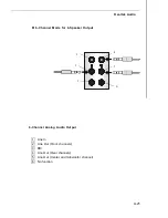
Page 90: ...mode properly in the software utility connect your speakers to the correct phone jacks in accordance with the setting in software utility n 2 Channel Mode for Stereo Speaker Output 1 Line In 2 Line O...

Page 91: ...MS 7577 Mainboard A 20 a n 4 Channel Mode for 4 Speaker Output 4 Channel Analog Audio Output 1 Line In 2 Line Out Front channels 3 MIC 4 Line Out Rear channels 5 No function 6 No function 3 1 2 6 4 5...

Page 92: ...ek Audio n 6 Channel Mode for 6 Speaker Output 6 Channel Analog Audio Output 1 Line In 2 Line Out Front channels 3 MIC 4 Line Out Rear channels 5 Line Out Center and Subwoofer channel 6 No function 1...

Page 93: ...Out Front channels 3 MIC 4 Line Out Rear channels 5 Line Out Center and Subwoofer channel 6 Line Out Side channels 1 2 6 4 5 3 Important To enable 7 1 channel audio out function on Vista operating sy...

Page 94: ...to monitor or configure the hard ware status of MSI Motherboard in windows such as CPU clock voltage fan speed and temperature Before you install the Overclocking Center please make sure the system ha...

Page 95: ...ng with your motherboard path Utility MSI Utility Overclocking Center it will have a short cut icon on the desktop and a short cut path in your Start up menu You may double click on each icon to activ...

Page 96: ...Center System Info In the System Info screen you can read the information of motherboard memory PCI Motherboard Click Motherboard to read the information of motherboard BIOS installed CPU and install...

Page 97: ...7 Mainboard Memory Click Memory to read the information of each memory DIMM slot You can select a DIMM slot you want to read from the SPD list PCI Click PCI to read the information of devices on the m...

Page 98: ...The settings in Novice menu are not adjustable Click DOT to enter the DOT screen In DOT you can select the basic setting to reach optimal performance in Novice menu or you can adjust advanced values...

Page 99: ...vance menu you can adjust the values for each environment setting default setting Click the Cooling Silence Default Game Cinema button to enter it s setting menu Please refer to the following descript...

Page 100: ...below the button then select a value Click the arrow sign and the drop down menu will appear In the System Warning block you can set the maximum CPU system temperature and the minimum CPU system fan...

Page 101: ...lick the Load button and choose a saved user setting to load the settings for the system Important Every time you turn off the system the settings will be restored to the factory default If you want t...

Page 102: ...concurrently striping data across multiple drives RAID 1 makes sure data is not lost if a drive fails as data is simultaneously written to two drives Drives configured for RAID Strip ing are said to...

Page 103: ...S During bootup a screen similar to the one below will appear for about few seconds Press Ctrl F to enter FastBuild utility The FastBuild menu screen will appear The Main Menu is used to choose the op...

Page 104: ...C 3 SB750 SATA RAID View Drives Assignments This window displays the model number capacities and assignment of the drives physically attached to the SATA host adapter...

Page 105: ...lan the data storage strategy RAID sets can be created either automatically or to allow the greatest flexibility manually 1 Press 2 on the Main Menu screen to enter the Define LD Menu 2 Press the arro...

Page 106: ...e arrow key to choose the hard drives which you want to make part of the LD use the space key to change the assignment to Y Then press Ctrl Y to save the configuration 5 A message will show up on the...

Page 107: ...tion is done the screen shows the LD information as below Press ESC key to the main screen 7 Press ESC key to exit the utility a message System is going to REBOOT Are You Sure will display answer Y to...

Page 108: ...LD on the main screen 2 Choose a LD No you want to delete and press Del or Alt D delete the RAID set 3 On the next screen a message will display to inform you press Ctrl Y to delete the RAID set or o...

Page 109: ...SI Adapters 6 Select the compatible RAID controller for 32 bit 64 bit version system and then press ENTER 7 The next screen should confirm that you have selected the RAID controller Press ENTER again...

Page 110: ...MSI DVD into the DVD ROM drive 2 The DVD will auto run and the setup screen will appear 3 Under the Driver tab click on AMD chipset drivers by your need The AMD chipset drivers includes RAID Driver 4...

Page 111: ...ter Manager Appendix D This appendix will assist users in configuring and enabling JMB322 RAID SATA7 SATA8 func tionality on platform The DRIVER BOOSTER MANAGER supports RAID level 0 striping RAID lev...

Page 112: ...ing the hard drive I O load across independent channels greatly improves I O performance RAID 1 provides data redundancy by mirroring data between the hard drives and provides enhanced read performanc...

Page 113: ...d below to install the Drive Booster Manager 1 Insert the application DVD into the DVD ROM drive The setup screen will automatically appear 2 Click Utility 3 Click Drive Booster Manager to install it...

Page 114: ...will find SATA drive information View SATA Drive Information Click the Drive Booster Information button and the information of all hard disks will display on the right side of the window You may clic...

Page 115: ...he Drive Booster Information screen 2 Click the Drive Booster Configuration button and select a RAID mode you want to create Then click the Apply to apply the RAID creation a The speed mode correspond...

Page 116: ...ally want to perform this creation Important You will lose all data on the SATA drives when you perform this creation Please ensure to back up all date in the SATA hard drives before performing this c...

Page 117: ...r a new password in the New Password box and enter the password again in the confirm password box to confirm the password Then click OK Important A password is available for a volume only That is to s...

Page 118: ...Apply to remove the RAIID mode 3 A warning message will appear to remind you that the data will be erased Press the Yes if you really want to perform this task Please confirm the volume is the one you...

Page 119: ...ooster Manager 4 A warning will appear to inform you that the deletion is finished Click OK to close the window Event Log Click the Event Log button all of the significant events will be listed Event...

Reviews: