background image

90

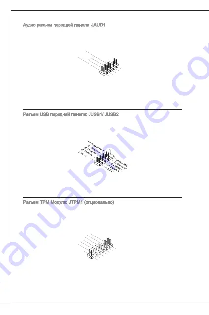
Аудио разъем передней панели: Jaud

Разъем позволяет подключить аудио на передней панели. Он соответствует 

спецификации intel

®

 Front Panel i/o Connectivity design Guide.

1.M

IC L

3.M

IC R

10.H

ead P

hone

 Dete

ction

5.He

ad P

hone

 R

7.SE

NSE

_SE

ND

9.He

ad P

hone

 L

8.No

 Pin

6.M

IC D

etec

tion

4.PR

ESE

NCE

#

2.Gro

und

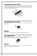
Разъем uSB передней панели: JuSB/ JuSB2

Разъем, который совместим со спецификацией intel

®

 i/o Connectivity design 

Guide,  идеален  для  подключения  таких  высокоскоростных  периферийных 

устройств как uSB Hdd, цифравых камер, MP плееров, принтеров, модемов 

и т.д.

Разъем tPM Модуля: JtPM (опционально)

Этот разъем предназначен для подключения tPM (trusted Platform Module) 

модуля. За дополнительной информацией и возможностями использования 

обратитесь к руководству платформы безопасности tPM.

10.N

o Pin

14.G

roun

d

8.5V

 Pow

er

12.G

roun

d

6.Se

rial IR

Q

4.3.3

V Po

wer

2.3V

 Stan

dby p

ower

1.LP

C Clo

ck

3.LP

C Re

set

5.LP

C ad

dres

s & d

ata p

in0

7.LP

C ad

dres

s & d

ata p

in1

9.LP

C ad

dres

s & d

ata p

in2

11.L

PC a

ddre

ss &

 data

 pin3

13.L

PC F

ram

e

Summary of Contents for MS-7615

Page 1: ...ence by one or more of the measures listed below Reorient or relocate the receiving antenna Increase the separation between the equipment and receiver Connect the equipment into an outlet on a circuit...

Page 2: ...NVIDIA Corporation ATI is registered trademark of ATI Technologies Inc AMD is registered trademarks of AMD Corporation Intel is registered trademarks of Intel Corporation Windows is registered tradem...

Page 3: ...on the equipment should be noted Never pour any liquid into the opening that can cause damage or cause elec trical shock If any of the following situations arises get the equipment checked by a ser vi...

Page 4: ...kommunale Abf lle entsorgt werden MSI hat europaweit verschiedene Sammel und Recyclingunternehmen beauftragt die in die Europ ische Union in Verkehr gebrachten Produkte am Ende seines Lebenszyklus zur...

Page 5: ...ducten die de merknaam MSI dragen en verkocht zijn in de EU Deze goederen kunnen geretourneerd worden op lokale inzamelingspunten SRPSKI Da bi za titili prirodnu sredinu i kao preduze e koje vodi ra u...

Page 6: ...h MAGYAR Annak rdek ben hogy k rnyezet nket megv dj k illetve k rnyezetv d k nt fell pve az MSI eml kezteti nt hogy Az Eur pai Uni EU 2005 augusztus 13 n hat lyba l p az elektromos s elektronikus bere...

Page 7: ...BIOS Setup 22 27 27 28 30 31 31 BIOS 40 fran AIS 45 Pour commencer 45 SP CIFICATIONS 46 Trous taraud s 48 Panneau arri re 49 Installation du mat riel 49 R glage bios 58 Deutsch 63 eINLEITUNG 63 SPEZIF...

Page 8: ...99 99 100 102 103 103 BIOS 112 117 117 118 120 121 121 BIOS 130 135 135 136 138 I O 139 139 BIOS 148...

Page 9: ...ATX mainboard The NF725 C35 NF725 C21 series is design based on NVIDIA Ge Force 7025 nForce 630a chipset for optimal system efficiency Designed to fit the advanced AMD AM3 processor the NF725 C35 NF7...

Page 10: ...LAN Supports LAN 10 100 1000 Fast Ethernet by Realtek RTL8111E for NF725 C35 Supports LAN 10 100 Fast Ethernet by Realtek RTL8105E for NF725 C21 Audio Chip integrated by Realtek ALC887 Supports 7 1 c...

Page 11: ...port 3 3V 5V PCI bus Interface Form Factor ATX 30 5 cm X 19 0 cm Mounting 6 mounting holes If you need to purchase accessories and request the part numbers you could search the product web page and fi...

Page 12: ...is Screw holes Refer above picture to install standoffs in the appropriate locations on chassis and then screw through the mainboard screw holes into the standoffs Important To prevent damage to the m...

Page 13: ...nded wrist strap before handling computer components Static electricity may damage the components CPU Cooler Installation for AM3 When you are installing the CPU make sure the CPU has a cooler attache...

Page 14: ...ingers pressing tightly on top of the CPU to make sure the CPU is properly and completely embedded into the socket Position the cooling set onto the retention mecha nism Hook one end of the clip to ho...

Page 15: ...ry module is properly in serted in the DIMM slot The plastic clip at each side of the DIMM slot will automatically close 2 Notch Volt Important DDR3 memory modules are not interchangeable with DDR2 an...

Page 16: ...5 V 1 0 1 2 V 2 0 R e s 8 P W R O K 2 3 5 V 1 1 1 2 V 2 1 5 V 9 5 V S B 2 4 G r o u n d 1 2 3 3 V ATX 8 Pin Power Connector JPWR2 This 12V power connector is used to provide power to the CPU 7 1 2 V 3...

Page 17: ...Monitor chipset on board you must use a specially designed fan with speed sensor to take advantage of the CPU fan control 1 G r o u n d 2 1 2 V 3 S e n s o r N o U s e 1 G r o u n d 2 1 2 V 3 S e n s...

Page 18: ...ide is ideal for connecting high speed USB interface peripherals such as USB HDD digital cam eras MP3 players printers modems and the like TPM Module Connector JTPM1 optional This connector connects t...

Page 19: ...rs are for electrical connection to the front panel switches and LEDs The JFP1 is compliant with Intel Front Panel I O Connectivity Design Guide 1 3 1 0 N o P i n 5 R e s e t S w i t c h H D D L E D P...

Page 20: ...5 P R N D 1 7 P R N D 2 9 P R N D 3 1 1 P R N D 4 1 3 P R N D 5 1 5 P R N D 6 1 7 P R N D 7 1 9 A C K 2 1 B U S Y 2 3 P E 2 5 S L C T Clear CMOS Jumper JBAT1 There is a CMOS RAM onboard that has a pow...

Page 21: ...men tation for the expansion card to configure any necessary hardware or software set tings for the expansion card such as jumpers switches or BIOS configuration PCI Interrupt Request Routing When add...

Page 22: ...the system by simultaneously pressing Ctrl Alt and De lete keys Main Page Standard CMOS Features Use this menu for basic system configurations such as time date etc Advanced BIOS Features Use this me...

Page 23: ...only Overclocking Profile Use this menu to save load your settings to from CMOS for BIOS Load Fail Safe Defaults Use this menu to load the BIOS default values that are factory settings for system oper...

Page 24: ...lower CPU speed and power consumption Important To ensure that Cool n Quiet function is activated and will be working properly it is required to double confirm that Run BIOS Setup and select Cell Men...

Page 25: ...rols the command rate Selecting 1T makes DRAM signal controller to run at 1 clock cycle rate Selecting 2T makes DRAM signal controller run at 2 clock cycles rate DCT Unganged Mode This feature is used...

Page 26: ...mance But if you are plagued by EMI select the value of Spread Spectrum for EMI reduction The greater the Spread Spectrum value is the greater the EMI is reduced and the system will become less stable...

Page 27: ...27 MS 7615 NF725 C35 NF725 C21 MS 7615 v2 x ATX NF725 C35 NF725 C21 NVID IA GeForce 7025 nForce 630a AMD AM3 NF725 C35 NF725 C21 JCOM1...

Page 28: ...25 nForce630a DDR3 1600 1066 800 SDRAM 8GB 2 DDR3 DIMMs 240 1 5V http www msi com index php func testreport LAN Realtek RTL8111E NF725 C35 LAN 10 100 1000 Fast Ethernet Realtek RTL8105E NF725 C21 LAN...

Page 29: ...29 MS 7615 PCIE x16 1 PCIE x1 1 PCI 4 3 3V 5V PCI ATX 30 5 cm X 19 0 cm 6 http www msi com index php...

Page 30: ...30 I O...

Page 31: ...31 MS 7615 AM3 CPU CPU CPU CPU CPU PS 2 PS 2 USB LAN USB USB...

Page 32: ...32 90 CPU CPU CPU CPU CPU CPU CPU CPU CPU 2 4 5 6 7 8...

Page 33: ...33 MS 7615 DIMM DIMM DIMM DIMM DIMM 2 DDR3 DDR2 DDR3 DDR3 DDR3 DIMM DIMM DIMM1...

Page 34: ...G r o u n d 5 G r o u n d 1 8 G r o u n d 6 5 V 1 9 G r o u n d 7 G r o u n d 2 2 5 V 1 0 1 2 V 2 0 R e s 8 P W R O K 2 3 5 V 1 1 1 2 V 2 1 5 V 9 5 V S B 2 4 G r o u n d 1 2 3 3 V ATX 8 JPWR2 12V CPU...

Page 35: ...12V 12V GND CPU 1 G r o u n d 2 1 2 V 3 S e n s o r N o U s e 1 G r o u n d 2 1 2 V 3 S e n s o r 4 C o n t r o l CPUFAN SYSFAN1 3 S PDIF JSP1 S PDIF 3 V C C 2 S P D I F 1 G r o u n d CD JCD1 4 R 3 G...

Page 36: ...n d USB JUSB1 JUSB2 Intel I O Connectivity Design Guide USB HDD MP3 USB TPM JTPM1 TPM Trusted Platform Module TPM 1 0 N o P i n 1 4 G r o u n d 8 5 V P o w e r 1 2 G r o u n d 6 S e r i a l I R Q 4 3...

Page 37: ...N o P i n 5 R e s e t S w i t c h H D D L E D P o w e r S w i t c h P o w e r L E D 7 9 R e s e r v e d 8 6 4 2 JFP1 1 G r o u n d 3 S u s p e n d L E D 5 P o w e r L E D 7 N o P i n 8 6 4 2 Buzzer Sp...

Page 38: ...D 2 4 G r o u n d 2 2 G r o u n d 2 6 N o P i n 2 0 G r o u n d 1 8 G r o u n d 1 6 G r o u n d 1 R S T B 3 P R N D 0 5 P R N D 1 7 P R N D 2 9 P R N D 3 1 1 P R N D 4 1 3 P R N D 5 1 5 P R N D 6 1 7...

Page 39: ...39 MS 7615 PCI Express PCIE PCIE The PCIE x16 The PCIE x1 PCI PCI LAN SCSI USB PCI BIOS PCI interrupt request line IRQ I R Q PCI IRQ PCI 1 2 3 4 PCI 1 C D A B PCI 2 B C D A PCI 3 A B C D PCI 4 D A B C...

Page 40: ...IOS POST Power On Self Test DEL DEL DE L OFF On RESET Ctrl Alt Delete Standard CMOS Features CMOS Advanced BIOS Features BIOS Integrated Peripherals Power Management Setup H W Monitor H W CPU Green Po...

Page 41: ...1 MS 7615 BIOS Setting Password BIOS BIOS Cell Menu M Flash M BIOS FAT FAT32 Overclocking Profile BIOS CMOS Load Fail Safe Defaults BIOS Load Optimized Defaults Save Exit Setup CMOS Exit Without Savin...

Page 42: ...AMD Cool n Quiet AMD CPU SVM Support SVM SVM AMD Cool n Quiet AMD CPU BIOS Cell Menu Cell Menu AMD Cool n Quiet Enabled Windows Pow erOptions Properties Power schemes Minimal Power Management Adjust...

Page 43: ...nfiguration DRAM Enter DRAM Timing Mode DRAM Auto DRAM 1T 2T Memory Timing 1T 2T DRAM Timing Manual 1T DRAM 1 2T DRAM 2 DCT Unganged Mode DCT 2 64 DCT 128 FSB DRAM Ratio FSB DRAM FSB Adjusted DRAM Fre...

Page 44: ...44 Spread Spectrum EMI EMI flatter curve EMI EMI EMI EMI EMI Load Optimized Defaults...

Page 45: ...x Les s ries NF725 C35 NF725 C21 sont bas es sur les puces NVIDIA GeForce 7025 nForce 630a offrant un syst me tr s perfor mant La carte fonctionne avec les processeurs AMD AM3 avanc s les s ries NF72...

Page 46: ...1000 Fast Ethernet par Realtek RTL8111E pour NF725 C35 Supporte LAN 10 100 Fast Ethernet par Realtek RTL8105E pour NF725 C21 Audio Puces int gr es par Realtek ALC887 Supporte 7 1 canaux audio out Conf...

Page 47: ...rtent l Interface bus PCI 3 3V 5V Dimension ATX 30 5 cm X 19 0 cm Montage 6 trous de montage Si vous d sirez acheter des accessoires et vous avez besoin de num ro des pi ces vous pouvez chercher sur l...

Page 48: ...r f rer la figure pour installer le support dans une position ap propri e sur le ch ssis et puis de fixer la carte travers les trous taraud s sur le support Important Pour pr venir les endommages la...

Page 49: ...les instructions de montage pour viter d endommager quoi que ce soit Intallation du CPU et le ventilateur pour AM3 Quand vous installez votre CPU assurez vous que le CPU poss de d un sys t me de refro...

Page 50: ...nt et compl tement int gr dans la douille Posez le ventilateur sur le m canisme de r ten tion Crochez un c t du clip d abord Puis appuyez sur l autre c t du clip pour fixer le ventilateur sur le haut...

Page 51: ...t Vous ne opuvez presque pas voir le doigt d or si le module de m moire est correctement ins r dans le slot DIMM Les clips en plastique situ s de chaque c t du slot DIMM se ferment au tomatiquement 2...

Page 52: ...1 1 1 2 V 2 1 5 V 9 5 V S B 2 4 G r o u n d 1 2 3 3 V Connecteur d alimentation ATX 8 pin JPWR2 Ce connecteur d alimentation de 12V sert alimenter le CPU 7 1 2 V 3 G r o u n d 5 1 2 V 1 G r o u n d 8...

Page 53: ...Monitor int gr vous devez utiliser un ventilateur ayant ces caract ristiques si bous voulez contr ler le ven tilateur du CPU 1 G r o u n d 2 1 2 V 3 S e n s o r N o U s e 1 G r o u n d 2 1 2 V 3 S e...

Page 54: ...l pour connecter les USB p riph rique d Interface de haute vitesse tel que USB HDD cam ra num rique lecteur MP3 imprimants modems et etc Connecteur de Module TPM JTPM1 en option Ce connecteur est reli...

Page 55: ...nnexion lectriques aux cummutateurs et LEDs Le JFP1 est compatible ave Intel Front Panel I O Connectivity Design Guide 1 3 1 0 N o P i n 5 R e s e t S w i t c h H D D L E D P o w e r S w i t c h P o w...

Page 56: ...R N D 5 1 5 P R N D 6 1 7 P R N D 7 1 9 A C K 2 1 B U S Y 2 3 P E 2 5 S L C T Cavalier d effacement CMOS JBAT1 Le CMOS RAM int gr re oit une alimentation d une batterie externe qui per met de garder...

Page 57: ...e le PC n est pas reli au secteur Lisez le documentation pour faire les configurations n cessaires du mat riel ou du logiciel de la carte d extension tels que cavaliers commutateurs ou la configuratio...

Page 58: ...elete Page Principale Standard CMOS Features Utilisez ce menu pour param trer des l ments standards du BIOS tel que l heure la date etc Advanced BIOS Features Utilisez ce menu pour r gler les articles...

Page 59: ...tilisez ce menu pour conserver charger vos r glages de CMOS pour BIOS Load Fail Safe Defaults Utilisez ce menu pour charger les valeurs par d faut du BIOS les r glages de la manufacture pour l op rati...

Page 60: ...CPU et la consommation d alimentation Important Afin d assurer que la fonction Cool n Quiet est activ e et qu elle marchera cor rectement il est n cessaire de confirmer doublement que Fonctionnez les...

Page 61: ...x d ordre de SDRAM La s lection en 1T fait fonctionner en taux de 1 cycle d horloge au contr leur du signaux du DRAM La s lection en 2T fait fonctionner en taux de 2 cycles d horloge au contr leur du...

Page 62: ...s performances optimales Dans le cas contraire choisissez Spread Spectrum pour r duire les EMI Plus la valeur Spread Spectrum est importante plus les EMI sont r duites et le syst me devient moins stab...

Page 63: ...s NF725 C35 NF725 C21 Serie basiert auf dem NVID IA GeForce 7025 nForce 630a Chipsatz und erm glicht so ein optimales und effizientes System Entworfen um den hochentwickelten AMD AM3 Prozessor das NF7...

Page 64: ...thernet ber Realtek RTL8111E f r NF725 C35 Unterst tzt LAN 10 100 Fast Ethernet ber Realtek RTL8105E f r NF725 C21 Audio Onboard Soundchip Realtek ALC887 7 1 Kanal Audio Ausgang Erf llt die Azalia Spe...

Page 65: ...platz 4 PCI Steckpl tze unterst tzen 3 3V 5V PCI Bus Interface Form Faktor ATX 30 5 cm X 19 0 cm Montage 6 Montagebohrungen Wenn Sie f r Bestellungen von Zubeh r Teilenummern ben tigen finden Sie dies...

Page 66: ...e das obige Bild um Abstandshalter in den entsprechenden Orten auf Chassis installieren und dann Schraube durch das Mainboard Schrauben l cher in den Abstandshaltern WICHtIG Zur Verh tung von Sch den...

Page 67: ...aus vorsichtig und halten Sie sich an die vorgegebene Vorgehensweise beim Einbau CPU Cooler Installation for AM3 Wenn Sie die CPU einbauen stellen Sie bitte sicher dass Sie auf der CPU einen K hler an...

Page 68: ...es Vorgangs durch permanenten Fingerdruck von oben um sicherzustellen dass die CPU richtig und vollst ndig im Sockel sitzt Setzen Sie den K hler auf die K hlerhalterung und hacken Sie zuerst ein Ende...

Page 69: ...kaum sehen Pr fen Sie von Hand ob das Arbeitsspeichermodul von den seitlichen B geln am DIMM Steckplatz richtig gehalten wird 2 Kerbe Volt Wichtig DDR3 und DDR2 k nnen nicht untereinander getauscht w...

Page 70: ...1 1 1 2 V 2 1 5 V 9 5 V S B 2 4 G r o u n d 1 2 3 3 V ATX 8 Pin Power Connector JPWR2 Dieser 12V Stromanschluss wird verwendet um die CPU mit Strom zu versor gen 7 1 2 V 3 G r o u n d 5 1 2 V 1 G r o...

Page 71: ...nboard einen Chipsatz zur berwachung der Systemhardware und Steuerung der L fter dann brauchen Sie einen speziellen L fter mit Tacho um diese Funktion zu nutzen 1 G r o u n d 2 1 2 V 3 S e n s o r N o...

Page 72: ...uide und ist bestens geeignet Hochgeschwindigkeits USB Periph erieger te anzuschlie en wie z B USB Festplattenlaufwerke Digitalkameras MP3 Player Drucker Modems und hnliches TPM Modul Anschluss JTPM1...

Page 73: ...s der Schalter und LEDs des Frontpaneels JFP1 erf llt die Anforderungen des Intel Front Panel I O Con nectivity Design Guide 1 3 1 0 N o P i n 5 R e s e t S w i t c h H D D L E D P o w e r S w i t c h...

Page 74: ...3 P R N D 5 1 5 P R N D 6 1 7 P R N D 7 1 9 A C K 2 1 B U S Y 2 3 P E 2 5 S L C T Steckbr cke zur CMOS L schung JBAT1 Der Onboard CMOS Speicher RAM wird ber eine zus tzliche Betterie mit Strom versorg...

Page 75: ...iterungskarte installieren oder entfernen Denken Sie bitte auch daran die Dokumentation der Erweiterungskarte zu lesen um notwen dige Hardware oder Softwareeinstellungen f r die Erweiterungskarte wie...

Page 76: ...dazu den Power On Anschalter oder den Reset Knopf Alternativ bet tigen Sie die Tastenkombination Ctrl Alt und Delete um einen Neustart zu er zwingen Main Page Standard CMOS Features In diesem Men k n...

Page 77: ...vornehmen M Flash In diesem Men k nnen Sie das BIOS vom Speicher Antrieb abtasten aufblinken nur FAT FAT32 Format Overclocking Profile Abspeichern laden die Einstellungen im vom CMOS f r BIOS Load Fai...

Page 78: ...Feature Dr cken Sie die Eingabetaste Enter um das Untermen aufzurufen AMD Cool n Quiet Die Cool n Quiet Technologie kann die CPU Geschwindigkeit und den Strom verbrauch effizient und dynamisch herabse...

Page 79: ...uenz der CPU NB Nur Anzeige MEMORY Z Dr cken Sie die Eingabetaste Enter um das Untermen aufzurufen DIMM1 2 Memory SPD Information Dr cken Sie die Eingabetaste Enter um das Untermen aufzurufen Das Unte...

Page 80: ...obleme mit Interferenzen haben belassen Sie es bei der Einstellung Disabled ausgeschaltet um bestm gliche Systemstabilit t und leistung zu gew hrleisten Stellt f r sie EMI ein Problem dar w hlen Sie d...

Page 81: ...81 MS 7615 NF725 C35 NF725 C21 MS 7615 v2 x ATX NF725 C35 NF725 C21 NVIDIA Ge Force 7025 nForce 630a AMD AM3 JCOM1...

Page 82: ...7025 nForce630a DDR3 1600 1066 800 SDRAM Max 8GB 2 DDR3 DIMM 240 1 5V http www msi com index php func testreport LAN LAN 10 100 1000 Fast Ethernet Realtek RTL8111E NF725 C35 LAN 10 100 Fast Ethernet R...

Page 83: ...83 MS 7615 1 PCIE x16 1 PCIE x1 4 PCI PCI 3 3V 5V ATX 30 5 X 19 0 6 http www msi com index php...

Page 84: ...84...

Page 85: ...85 MS 7615 AM3 PS 2 PS 2 USB LAN USB USB...

Page 86: ...86 gold arrow CPU CPU CPU CPU CPU CPU CPU CPU Socket AM3 2 4 5 6 7 8...

Page 87: ...87 MS 7615 DIMM DIMM DIMM 2 DDR3 DDR2 DDR3 DDR3 DDR3 DIMM1...

Page 88: ...u n d 1 8 G r o u n d 6 5 V 1 9 G r o u n d 7 G r o u n d 2 2 5 V 1 0 1 2 V 2 0 R e s 8 P W R O K 2 3 5 V 1 1 1 2 V 2 1 5 V 9 5 V S B 2 4 G r o u n d 1 2 3 3 V 8 ATX JPWR2 12V 7 1 2 V 3 G r o u n d 5...

Page 89: ...d 2 1 2 V 3 S e n s o r N o U s e 1 G r o u n d 2 1 2 V 3 S e n s o r 4 C o n t r o l CPUFAN SYSFAN1 3 S PDIF Out JSP1 S PDIF Sony Philips Digital Interconnect Format 3 V C C 2 S P D I F 1 G r o u n...

Page 90: ...n d USB JUSB1 JUSB2 Intel I O Connectivity Design Guide USB HDD MP3 TPM JTPM1 TPM Trusted Platform Module TPM 1 0 N o P i n 1 4 G r o u n d 8 5 V P o w e r 1 2 G r o u n d 6 S e r i a l I R Q 4 3 3 V...

Page 91: ...o P i n 5 R e s e t S w i t c h H D D L E D P o w e r S w i t c h P o w e r L E D 7 9 R e s e r v e d 8 6 4 2 JFP1 1 G r o u n d 3 S u s p e n d L E D 5 P o w e r L E D 7 N o P i n 8 6 4 2 Buzzer Spea...

Page 92: ...D 2 4 G r o u n d 2 2 G r o u n d 2 6 N o P i n 2 0 G r o u n d 1 8 G r o u n d 1 6 G r o u n d 1 R S T B 3 P R N D 0 5 P R N D 1 7 P R N D 2 9 P R N D 3 1 1 P R N D 4 1 3 P R N D 5 1 5 P R N D 6 1 7...

Page 93: ...93 MS 7615 PCIE PCIE PCIE PCIE x16 PCIE x1 PCI PCI LAN SCSI USB PCI BIOS PCI IRQ interrupt request line PCI IRQ PCI 1 2 3 4 PCI 1 C D A B PCI 2 B C D A PCI 3 A B C D PCI 4 D A B C...

Page 94: ...POST DEL Press DEL to enter SETUP DEL SETUP RESET Ctrl Alt Delete Main Page Standard CMOS Features CMOS Advanced BIOS Features BIOS BIOS Integrated Peripherals Power Management Setup H W Monitor Gree...

Page 95: ...7615 BIOS Setting Password BIOS Cell Menu Cell M Flash BIOS FAT FAT32 Overclocking Profile CMOS BIOS Load Fail Safe Defaults BIOS Load Optimized Defaults Save Exit Setup CMOS Exit Without Saving Cell...

Page 96: ...Support SVM AMD Cool n Quiet Cool n Quiet CPU Cool n Quiet BIOS Setup Cell Menu AMD Cool n Quiet Cell Menu Enabled Windows Start Settings Control Panel Power Options Power Options Properties Minimal P...

Page 97: ...figuration Enter DRAM Timing Mode DRAM Auto 1T 2T Memory Timing DRAM Timing Mode Manual SDRAM 1T SDRAM 1T T clock cycles 2T SDRAM 2T DCT Unganged Mode 64 DCT 128 FSB DRAM Ratio FSB Adjusted DRAM Frequ...

Page 98: ...98 Spread Spectrum EMI Electromagnetic Interference Spread Spectrum Disabled Spread Spec trum Spread Spectrum Spread Spectrum Spread Spectrum BIOS...

Page 99: ...99 MS 7615 NF725 C35 NF725 C21 MS 7615 v2 x ATX NF725 C35 NF725 C21 NVIDIA GeForce 7025 nForce 630a AMD AM3 NF725 C35 NF725 C21 JCOM1...

Page 100: ...GHz NVIDIA GeForce7025 nForce630a DDR3 1600 1066 800 SDRAM 8GB 2 DDR3 DIMM 240pin 1 5V http www msi com index php func testreport LAN Realtek RTL8111E NF725 C35 10 100 1000 Realtek RTL8105E NF725 C21...

Page 101: ...101 MS 7615 1 PCIE x16 1 PCIE x1 4 PCI 3 3V 5V PCI ATX 30 5 X 19 0 6 http www msi com index php...

Page 102: ...102...

Page 103: ...103 MS 7615 AM3 CPU CPU CPU CPU CPU CPU CPU PS 2 PS 2 USB LAN Line In Line Out MIC USB USB...

Page 104: ...104 90 CPU CPU CPU CPU CPU CPU CPU CPU CPU AM3 CPU 2 4 5 6 7 8...

Page 105: ...105 MS 7615 DIMM 2 DDR3 DDR2 DDR3 DDR3 DDR3 DIMM1...

Page 106: ...1 7 G r o u n d 5 G r o u n d 1 8 G r o u n d 6 5 V 1 9 G r o u n d 7 G r o u n d 2 2 5 V 1 0 1 2 V 2 0 R e s 8 P W R O K 2 3 5 V 1 1 1 2 V 2 1 5 V 9 5 V S B 2 4 G r o u n d 1 2 3 3 V ATX 8 Pin JPWR2...

Page 107: ...GND 1 G r o u n d 2 1 2 V 3 S e n s o r N o U s e 1 G r o u n d 2 1 2 V 3 S e n s o r 4 C o n t r o l CPUFAN SYSFAN1 3 S PDIF Out JSP1 S PDIF Sony Philips 3 V C C 2 S P D I F 1 G r o u n d CD In JCD1...

Page 108: ...JUSB1 JUSB2 Intel I O USB USB HDD MP3 TPM JTPM1 TPM Trusted Platform Module TPM 1 0 N o P i n 1 4 G r o u n d 8 5 V P o w e r 1 2 G r o u n d 6 S e r i a l I R Q 4 3 3 V P o w e r 2 3 V S t a n d b y...

Page 109: ...S w i t c h H D D L E D P o w e r S w i t c h P o w e r L E D 7 9 R e s e r v e d 8 6 4 2 JFP1 1 G r o u n d 3 S u s p e n d L E D 5 P o w e r L E D 7 N o P i n 8 6 4 2 Buzzer Speaker JFP2 JCOM1 16 F...

Page 110: ...D 2 4 G r o u n d 2 2 G r o u n d 2 6 N o P i n 2 0 G r o u n d 1 8 G r o u n d 1 6 G r o u n d 1 R S T B 3 P R N D 0 5 P R N D 1 7 P R N D 2 9 P R N D 3 1 1 P R N D 4 1 3 P R N D 5 1 5 P R N D 6 1 7...

Page 111: ...111 MS 7615 PCI Express PCI Express PCI PCIE x16 PCIE x1 PCI PCI SCSI USB PCI BIOS PCI IRQ PCI IRQ PCI 1 2 3 4 PCI 1 C D A B PCI 2 B C D A PCI 3 A B C D PCI 4 D A B C...

Page 112: ...BIOS POST DEL Press DEL to enter SETUP DEL Setup RESET Ctrl Alt De lete Standard CMOS Features CMOS Advanced BIOS Features BIOS Integrated Peripherals Power Management Setup H W Monitor CPU Green Pow...

Page 113: ...ell Menu M Flash BIOS FAT FAT32 Overclocking Profile BIOS CMOS CMOS Load Fail Safe Defaults BIOS Load Optimized Defaults BIOS Save Exit Setup CMOS Setup Exit Without Saving CMOS Setup Current CPU DRAM...

Page 114: ...lMenu CellMenu AMDCool n Quiet Enabled Windows Start Settings Control Panel Power Options Power Options Properties Power schemes Minimal Power Management Adjust CPU FSB Frequency MHz CPU FSB MHz CPU M...

Page 115: ...d Mode DCT Unganged 64 bit DCT 128 bit FSB DRAM Ratio FSB DRAM FSB DRAM Adjusted DRAM Frequency MHz DRAM MHz Adjusted HT Link Frequency MHz HT HT Auto Disable PCI PCI E Frequency PCI PCI E Enabled PCI...

Page 116: ...116...

Page 117: ...117 MS 7615 NF725 C35 NF725 C21 MS 7615 v2 x ATX NF725 C35 NF725 C21 NVIDIA GeForce 7025 nForce 630a AMD AM3 NF725 C35 NF725 C21 JCOM1...

Page 118: ...z NVIDIA GeForce 7025 nForce 630a DDR2 1600 1066 800 SDRAM 8GB 2 DDR3 DIMMs 240pin 1 5V http www msi com index php func testreport LAN Realtek RTL8111E Gb LAN NF725 C35 Realtek RTL8105E 10 100 LAN NF7...

Page 119: ...119 MS 7615 PCIE x16 1 PCIE x1 4 PCI 3 3V 5V PCI ATX 30 5 X 19 0 6 http tw msi com...

Page 120: ...120...

Page 121: ...121 MS 7615 AM3 LAN PS 2 PS 2 USB USB USB...

Page 122: ...122 90 CPU CPU CPU CPU CPU CPU CPU CPU AM3 2 4 5 6 7 8...

Page 123: ...123 MS 7615 2 DDR3 DDR2 DDR2 DDR3 DDR3 DIMM1...

Page 124: ...d 5 G r o u n d 1 8 G r o u n d 6 5 V 1 9 G r o u n d 7 G r o u n d 2 2 5 V 1 0 1 2 V 2 0 R e s 8 P W R O K 2 3 5 V 1 1 1 2 V 2 1 5 V 9 5 V S B 2 4 G r o u n d 1 2 3 3 V ATX 8 Pin JPWR2 12V CPU 7 1 2...

Page 125: ...u n d 2 1 2 V 3 S e n s o r N o U s e 1 G r o u n d 2 1 2 V 3 S e n s o r 4 C o n t r o l CPUFAN SYSFAN1 3 S PDIF Out JSP1 S PDIF Sony Philip Digital Interconnect Format 3 V C C 2 S P D I F 1 G r o u...

Page 126: ...G r o u n d USB JUSB1 JUSB2 Intel USB USB MP3 TPM JTPM1 TPM 1 0 N o P i n 1 4 G r o u n d 8 5 V P o w e r 1 2 G r o u n d 6 S e r i a l I R Q 4 3 3 V P o w e r 2 3 V S t a n d b y p o w e r 1 L P C C...

Page 127: ...t S w i t c h H D D L E D P o w e r S w i t c h P o w e r L E D 7 9 R e s e r v e d 8 6 4 2 JFP1 1 G r o u n d 3 S u s p e n d L E D 5 P o w e r L E D 7 N o P i n 8 6 4 2 Buzzer Speaker JFP2 JCOM1 16...

Page 128: ...D 2 4 G r o u n d 2 2 G r o u n d 2 6 N o P i n 2 0 G r o u n d 1 8 G r o u n d 1 6 G r o u n d 1 R S T B 3 P R N D 0 5 P R N D 1 7 P R N D 2 9 P R N D 3 1 1 P R N D 4 1 3 P R N D 5 1 5 P R N D 6 1 7...

Page 129: ...129 MS 7615 PCI Express PCI Express PCI Express PCIE x16 PCIE x1 PCI SCSI USB PCI BIOS PCI IRQ Interrupt request line PCI IRQ PCI 1 2 3 4 PCI 1 C D A B PCI 2 B C D A PCI 3 A B C D PCI 4 D A B C...

Page 130: ...130 BIOS POST DEL RESET Ctrl Alt Delete Standard CMOS Features CMOS Advanced BIOS Features BIOS Integrated Peripherals Power Management Setup H W Monitor Green Power Press DEL to enter SETUP DEL...

Page 131: ...IOS Setting Password BIOS BIOS Cell Menu M Flash USB flash BIOS Overclocking Profile BIOS CMOS BIOS CMOS Load Fail Safe Defaults BIOS Load Optimized Defaults BIOS Save Exit Setup CMOS Exit Without Sav...

Page 132: ...l n Quiet CPU SVM Support SVM SVM AMD Cool n Quiet CPU Cool n Quiet BIOS Cell Menu AMD Cool n Quiet Enabled Windows Adjust CPU FSB Frequency MHz CPU CPU Adjust CPU Ratio CPU CPU Adjusted CPU Frequency...

Page 133: ...DRAM 1T SDRAM T 2T DCT Unganged Mode Unganged 64 bit DCT 128 bit FSB DRAM Ratio FSB FSB Adjusted DRAM Frequency MHz Adjusted HT Link Frequency MHz HT Link HT Link Auto Disable PCI PCI E Frequency PCI...

Page 134: ...134...

Page 135: ...135 MS 7615 NF725 C35 NF725 C21 MS 7615 v2 x ATX NF725 C35 NF725 C21 NVIDIA GeForce 7025 nForce 630a AMD AM3 JCOM1...

Page 136: ...NVIDIA GeForce7025 nForce630a DDR3 1600 1066 800 SDRAM 8GB DDR3 DIMM 2 240 1 5V Web http www msi com index php func testreport LAN Realtek RTL8111E LAN 10 100 1000 NF725 C35 Realtek RTL8105E LAN 10 10...

Page 137: ...137 MS 7615 PCIE x16 1 PCIE x1 1 PCI 4 3 3V 5V PCI ATX 30 5 cm X 19 0 cm 6 Web http www msi com index php...

Page 138: ...138 I O...

Page 139: ...139 MS 7615 I O AM3 CPU CPU CPU CPU CPU CPU PS 2 PS 2 USB LAN Line In Line Out MIC USB USB...

Page 140: ...140 90 CPU CPU CPU CPU CPU CPU CPU CPU CPU CPU CPU CPU 2 4 5 6 7 8...

Page 141: ...141 MS 7615 DIMM DIMM DIMM 2 DDR3 DDR2 DDR2 DIMM1...

Page 142: ...r o u n d 5 G r o u n d 1 8 G r o u n d 6 5 V 1 9 G r o u n d 7 G r o u n d 2 2 5 V 1 0 1 2 V 2 0 R e s 8 P W R O K 2 3 5 V 1 1 1 2 V 2 1 5 V 9 5 V S B 2 4 G r o u n d 1 2 3 3 V ATX 8 JPWR2 12V CPU 7...

Page 143: ...3 12V 12V GND 1 G r o u n d 2 1 2 V 3 S e n s o r N o U s e 1 G r o u n d 2 1 2 V 3 S e n s o r 4 C o n t r o l CPUFAN SYSFAN1 3 S PDIF JSP1 5 1 7 1 3 V C C 2 S P D I F 1 G r o u n d CD JCD1 4 R 3 G r...

Page 144: ...I O Connectivity Design Guide USB HDD MP3 USB TPM JTPM1 TPM Trusted Platform Module TPM 1 0 N o P i n 1 4 G r o u n d 8 5 V P o w e r 1 2 G r o u n d 6 S e r i a l I R Q 4 3 3 V P o w e r 2 3 V S t a...

Page 145: ...w i t c h H D D L E D P o w e r S w i t c h P o w e r L E D 7 9 R e s e r v e d 8 6 4 2 JFP1 1 G r o u n d 3 S u s p e n d L E D 5 P o w e r L E D 7 N o P i n 8 6 4 2 Buzzer Speaker JFP2 JCOM1 16550A...

Page 146: ...6 P I N I T 4 E R R 2 A F D 2 4 G r o u n d 2 2 G r o u n d 2 6 N o P i n 2 0 G r o u n d 1 8 G r o u n d 1 6 G r o u n d 1 R S T B 3 P R N D 0 5 P R N D 1 7 P R N D 2 9 P R N D 3 1 1 P R N D 4 1 3 P...

Page 147: ...147 MS 7615 PCI Express PCI Express PCI Express PCIE x16 PCIE x1 PCI PCI BIOS PCI CPU PC PCI IRQ 1 2 3 4 PCI 1 C D A B PCI 2 B C D A PCI 3 A B C D PCI 4 D A B C...

Page 148: ...er On Self Test DEL Press DEL to enter SETUP DEL DEL RESET Ctrl Alt Delete Standard CMOS Features CMOS Advanced BIOS Features BIOS BIOS Integrated Peripherals IDE Power Management Setup H W Monitor H...

Page 149: ...MS 7615 BIOS Setting Password BIOS Cell Menu M Flash USB BIOS FAT FAT32 Overclocking Profile CMOS CMOS Load Fail Safe Defaults BIOS Load Optimized Defaults Save Exit Setup Exit Without Saving Cell Me...

Page 150: ...SVM SVM AMD Cool n Quiet Cool nQuiet Cool n Quiet BIOS Cell Menu Cell Menu AMD Cool n Quiet Enable Start Settings Control Pannel Power Options Power Options Properties Power schemes Minimal Power Man...

Page 151: ...ng Mode DRAM Auto DRAM 1T 2T Memory Timing 1T 2T DRAM Timing Mode Manual 1T DRAM 1T 2T 2T DCT Unganged Mode DCT Unganged 64 bit DCT 128 bit FSB DRAM Ratio FSB DRAM FSB Adjusted DRAM Frequency MHz DRAM...

Page 152: ...152 Spread Spectrum EMI Disabled Disabled Disabled Enabled Spread Spectrum Disabled Load Optimized Defaults BIOS...

Page 153: ...153 MS 7615...

Page 154: ...Pb Hg Cd Cr VI PBB PBDE PCB SJ T11363 2006 SJ T11363 2006 0 35 0 4 4 85 pins microprocessors 80 85 Flip Chippackages...

Reviews: