background image

Kr-5

한국어

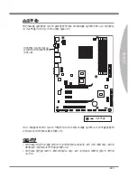
스크루 홀

메인보드를 설치할 때 섀시에 올바른 방향으로 메인보드를 설치해야 합니다. 메인보드

의 스크루 홀의 위치는 아래 그림과 같습니다.

위의 그림을 참조하여 섀시의 적절한 위치에 스탠드오프를 설치하고 스크루 홀을 통해 

스탠드오프에 메인보드를 고정합니다.

중요 사항

메인보드에 대한 손상을 방지하기 위해 메인보드 회로 및 섀시 간의 접촉 또는 섀시의 

불필요한 스탠드오프 장착을 금지합니다.
메인보드 합선을 피하기 위해 메인보드 또는 섀시 속에 금속 부품이 없는지 확인하

십시오.

스크루 홀

이 측면은 섀시의 I/O 실

드 위치인 뒤쪽으로 향해

야 합니다. 

S

O

C

K

E

T

A

M

3

Summary of Contents for MS-7660

Page 1: ...870A Fuzion series MS 7660 v2 x Mainboard G52 76601X5...

Page 2: ...n AMI is registered trademark of American Megatrends Inc Award is a registered trademark of Phoenix Technologies Ltd Sound Blaster is registered trademark of Creative Technology Ltd Realtek is registe...

Page 3: ...s and warnings on the equipment should be noted Never pour any liquid into the opening that could damage or cause electrical shock If any of the following situations arises get the equipment checked b...

Page 4: ...ect the interference by one or more of the measures listed below Reorient or relocate the receiving antenna Increase the separation between the equipment and receiver Connect the equipment into an out...

Page 5: ...Elektronik Altger te nicht mehr als kommunale Abf lle entsorgt werden MSI hat europaweit verschiedene Sammel und Recyclingunternehmen beauftragt die in die Europ ische Union in Verkehr gebrachten Prod...

Page 6: ...e producten die de merknaam MSI dragen en verkocht zijn in de EU Deze goederen kunnen geretourneerd worden op lokale inzamelingspunten SRPSKI Da bi za titili prirodnu sredinu i kao preduze e koje vodi...

Page 7: ...m stn ch sb rn ch MAGYAR Annak rdek ben hogy k rnyezet nket megv dj k illetve k rnyezetv d k nt fell pve az MSI eml kezteti nt hogy Az Eur pai Uni EU 2005 augusztus 13 n hat lyba l p az elektromos s...

Page 8: ...ctronic Equipment Statement v English En 1 Mainboard Specifications En 2 Quick Components Guide En 4 Screw Holes En 5 CPU Central Processing Unit En 6 Memory En 9 Power Supply En 11 Back Panel En 13 C...

Page 9: ...BIOS Kr 26 Kr 36 Jp 1 Jp 2 Jp 4 Jp 5 CPU Jp 6 Jp 9 Jp 11 I O Jp 13 Jp 15 Jp 21 Jp 22 Jp 23 LED Jp 25 BIOS Jp 26 Jp 36 Tc 1 Tc 2 Tc 4 Tc 5 CPU Tc 6 Tc 9 Tc 11 Tc 13 Tc 15 Tc 21 Tc 22 Tc 23 LED Tc 25 BI...

Page 10: ...Preface CPU Sc 6 Sc 9 Sc 11 Sc 13 Sc 15 Sc 21 Sc 22 Sc 23 LED Sc 25 BIOS Sc 26 Sc 36...

Page 11: ...English 870A Fuzion series Asia version...

Page 12: ...Channel mode For more information on compatible components please visit http www msi com index php func testreport LAN Supports Gb LAN 10 100 1000 by Realtek RTL8111E IEEE 1394 optional Chip integrate...

Page 13: ...0 port 1 IEEE 1394 port optional 1 LAN port 6 flexible audio ports On Board 2 USB 2 0 connectors 1 USB 3 0 connector 1 IEEE 1394 connector optional 1 Chassis Intrusion connector 1 S PDIF Out connecto...

Page 14: ...U En 6 CPUFAN En 16 DDR3 En 9 JCI1 En 15 JPWR1 En 11 JTPM1 En 20 SATA En 15 JCD1 En 18 JFP1 JFP2 En 17 JUSB1 2 En 18 JBAT1 En 21 JSP1 En 17 PCI En 24 PCIE En 23 TURBO1 En 22 JAUD1 En 16 SYSFAN1 En 16...

Page 15: ...sis and then screw through the mainboard screw holes into the standoffs Important To prevent damage to the mainboard any contact between the mainboard circuit and chassis or unnecessary standoffs moun...

Page 16: ...or thermal tape between the CPU and the heatsink to enhance heat dissipation Replacing the CPU While replacing the CPU always turn off the ATX power supply or unplug the power supply s power cord fro...

Page 17: ...into the socket and can not be seen Please note that any violation of the correct installation procedures may cause permanent damages to your mainboard 3 Press the CPU down firmly into the socket and...

Page 18: ...eye on your fingers because once the Safety Hook is disconnected from the fixed bolt the fixed lever will spring back instantly Position the cooling set onto the re tention mechanism Hook one end of t...

Page 19: ...e population rules for Dual Channel mode 1 DIMM1 DIMM2 DIMM3 DIMM4 2 DIMM1 DIMM2 DIMM3 DIMM4 Installed Empty Important DDR3 memory modules are not interchangeable with DDR2 and the DDR3 standard is no...

Page 20: ...until the golden finger on the memory module is deeply inserted in the DIMM slot The plastic clip at each side of the DIMM slot will automatically close when the memory module is properly seated Manua...

Page 21: ...ply as you like If you d like to use the 20 pin ATX power supply please plug your power supply along with pin 1 pin 13 1 3 3 3 V 1 3 3 V 1 4 1 2 V 2 3 3 V 1 5 G r o u n d 3 G r o u n d 1 6 P S O N 4 5...

Page 22: ...X 6 pin Power Connector PWRCONN1 This connector is used to provide power to the graphics card Important Make sure that all the connectors are connected to proper ATX power supplies to en sure stable o...

Page 23: ...the system will boot automatically Coaxial S PDIF Out This S PDIF Sony Philips Digital Interconnect Format connector is provided for digi tal audio transmission to external speakers through a coaxial...

Page 24: ...link is established On brighter pulsing The computer is communicating with another computer on the LAN Right Green Off 10 Mbits sec data rate is selected On 100 Mbits sec data rate is selected Orange...

Page 25: ...y Marvell 88SE9128 SATA3 SATA4 Important Please do not fold the Serial ATA cable into 90 degree angle Otherwise data loss may occur during transmission Chassis Intrusion Connector JCI1 This connector...

Page 26: ...t r o l CPUFAN SYSFAN1 2 Important Please refer to the recommended CPU fans at processor s official website or consult the vendors for proper CPU cooling fan CPUFAN supports fan control You can insta...

Page 27: ...o w e r L E D 7 N o P i n 8 6 4 2 Buzzer Speaker 1 3 1 0 N o P i n 5 R e s e t S w i t c h H D D L E D P o w e r S w i t c h P o w e r L E D 7 9 R e s e r v e d 8 6 4 2 JFP1 JFP2 S PDIF Out Connector...

Page 28: ...s and the like The MB layout in this figure is for reference only USB 2 0 Bracket optional USB 2 0 connector JUSB1 JUSB2 USB 3 0 connector USB3 Important Note that the pins of VCC and GND must be conn...

Page 29: ...1394 bracket The MB layout in this figure is for reference only 1394 Bracket optional Serial Port Connector JCOM1 This connector is a 16550A high speed communication port that sends receives 16 bytes...

Page 30: ...al for more details and usages 1 0 N o P i n 1 4 G r o u n d 8 5 V P o w e r 1 2 G r o u n d 6 S e r i a l I R Q 4 3 3 V P o w e r 2 3 V S t a n d b y p o w e r 1 L P C C l o c k 3 L P C R e s e t 5 L...

Page 31: ...the CMOS RAM the system can automati cally boot OS every time it is turned on If you want to clear the system configuration set the jumper to clear data JBAT1 Keep Data Clear Data 1 1 1 Important You...

Page 32: ...k after booting the system To disable the OC Genie function please press the button again after power off the system meanwhile the button light will off and unlock and the system will restore the defa...

Page 33: ...rd PCI Express x16 Slot PCI Express x1 Slot Important When adding or removing expansion cards make sure that you unplug the power sup ply first Meanwhile read the documentation for the expansion card...

Page 34: ...anwhile read the documentation for the expansion card to configure any necessary hardware or software settings for the expansion card such as jumpers switches or BIOS configuration PCI Interrupt Reque...

Page 35: ...Status Indicators CPU Phase LEDs SOCKET AM3 CPU Phase LEDs These LEDs indicate the current CPU power phase mode Follow the instructions below to read Lights Off CPU is in 1 phase power mode CPU is in...

Page 36: ...chapter are under continuous update for better system performance Therefore the description may be slightly dif ferent from the latest BIOS and should be held for reference only Upon boot up the 1st l...

Page 37: ...eys to select the item The on line description of the highlighted setup function is displayed at the bottom of the screen Sub Menu If you find a right pointer symbol appears to the left of certain fie...

Page 38: ...this menu to setup the items of the BIOS special enhanced features Integrated Peripherals Use this menu to specify your settings for integrated peripherals Power Management Setup Use this menu to spe...

Page 39: ...load the default values set by the BIOS vendor for stable system performance Load Optimized Defaults Use this menu to load the default values set by the mainboard manufacturer specifically for optima...

Page 40: ...system perfor mance Setup Date Time Select the Standard CMOS Features and press Enter to enter the Standard CMOS Features menu Adjust the Date Time fields 2 Save Exit Setup Use control keys to highlig...

Page 41: ...locks of CPU Memory and CPU NB speed Read only CPU Specifications Press Enter to enter the sub menu This submenu shows the information of installed CPU CPU Technology Support Press Enter to enter the...

Page 42: ...t all processors support Enhanced Halt state C1E Adjust CPU FSB Frequency MHz This item allows you to select the CPU Front Side Bus clock frequency in MHz OC Stepping This item will be enabled after y...

Page 43: ...default settings for system AMD Sempron tm II X2 Processor Important This CPU core unlocked behavior depends on the CPU ability characteristic and it is not guaranteed Depend on CPU s characteristic...

Page 44: ...oller to run at 1T T clock cycles rate Selecting 2T makes SDRAM signal controller run at 2T rate DCT Unganged Mode This feature is used to Integrate two 64 bit DCTs into a 128 bit interface Bank Inter...

Page 45: ...of CPU Memory and chipset Spread Spectrum When the mainboard s clock generator pulses the extreme values spikes of the pulses create EMI Electromagnetic Interference The Spread Spectrum function reduc...

Page 46: ...til ity and follow the pop up screen to complete the installation The Driver Utility DVD contains the Driver menu The Driver menu shows the available drivers Install the driver by your desire and to a...

Page 47: ...870A Fuzion Asia version...

Page 48: ...DDR3 1600 OC 1333 1066 DRAM 16GB 4 DDR3 DIMM http www msi com index php func testreport LAN Realtek RTL8111E Gb LAN 10 100 1000 IEEE 1394 VIA VT6315N 1 IEEE 1394 1 IEEE 1394 Realtek ALC892 ALC887 HD 8...

Page 49: ...PS 2 1 PS 2 1 CMOS 1 S PDIF 1 S PDIF 1 USB 2 0 6 USB 3 0 1 IEEE 1394 1 LAN 1 6 USB 2 0 2 USB 3 0 1 IEEE 1394 1 1 S PDIF 1 1 1 TPM 1 CD 1 OC Genie 1 PCIE x16 2 GPU ATI CrossFireXTM PCIE x1 2 PCI 1 3 3...

Page 50: ...R3 Kr 9 JCI1 Kr 15 JPWR1 Kr 11 JTPM1 Kr 20 SATA Kr 15 JCD1 Kr 18 JFP1 JFP2 Kr 17 JUSB1 2 Kr 18 JBAT1 Kr 21 JSP1 Kr 17 PCI Kr 24 PCIE Kr 23 TURBO1 Kr 22 JAUD1 Kr 16 SYSFAN1 Kr 16 JCOM1 Kr 19 SYSFAN2 Kr...

Page 51: ...Kr 5 I O SOCKET AM3...

Page 52: ...Kr 6 MS 7660 CPU CPU CPU CPU http www msi com index php func cpuform2 CPU CPU CPU CPU CPU ATX CPU AM3 CPU CPU...

Page 53: ...Kr 7 CPU CPU CPU CPU CPU CPU CPU CPU CPU 4 90 1 CPU 3 CPU CPU 2...

Page 54: ...Kr 8 MS 7660 6 7 CPU CPU 8 5...

Page 55: ...Kr 9 DIMM http www msi com index php func testreport DDR3 240 1 5V 72x2 144 48x2 96 2 1 DIMM1 DIMM2 DIMM3 DIMM4 2 DIMM1 DIMM2 DIMM3 DIMM4 DDR3 DDR2 DDR3 DDR3 DIMM DDR3 DIMM DIMM1 DIMM 4GB 16GB 15 GB...

Page 56: ...Kr 10 MS 7660 DIMM DIMM DIMM DIMM DIMM 1 2 3...

Page 57: ...n d 1 6 P S O N 4 5 V 1 7 G r o u n d 5 G r o u n d 1 8 G r o u n d 6 5 V 1 9 G r o u n d 7 G r o u n d 2 2 5 V 1 0 1 2 V 2 0 R e s 8 P W R O K 2 3 5 V 1 1 1 2 V 2 1 5 V 9 5 V S B 2 4 G r o u n d 1 2...

Page 58: ...Kr 12 MS 7660 ATX 6 PWRCONN1 ATX...

Page 59: ...MOS CMOS G3 S PDIF S PDIF Sony Philips Digital Interconnect Format S PDIF S PDIF Sony Philips Digital Interconnect Format USB 2 0 USB Universal Serial Bus USB USB 480Mbit s RS CS SS CMOS USB 2 0 USB 3...

Page 60: ...E 1394 IEEE 1394 IEEE 1394 USB 3 0 USB 3 0 USB 2 0 5 Gbit s USB 3 0 USB 3 0 USB 3 0 LAN RJ 45 LAN Local Area Network LAN LED LED LAN LAN LAN 10 Mbits sec 100 Mbits sec 1000 Mbits sec CD RS 4 5 1 7 1 C...

Page 61: ...Kr 15 ATA SATA1 8 ATA ATA MB SATA5_6 SATA7_8 SATA1_2 AMD SB710 SATA1 6 3Gb s Marvell 88SE9128 SATA7_8 6Gb s SATA3 SATA4 ATA 90 JCI1 BIOS 1 C I N T R U 2 G r o u n d...

Page 62: ...o n t r o l CPUFAN SYSFAN1 2 CPU CPU CPUFAN CPUFAN CPUFAN Control Center 3 4 CPUFAN JAUD1 Intel Front Panel I O Connectivity Design Guide 1 M I C L 3 M I C R 1 0 H e a d P h o n e D e t e c t i o n 5...

Page 63: ...d L E D 5 P o w e r L E D 7 N o P i n 8 6 4 2 Buzzer Speaker 1 3 1 0 N o P i n 5 R e s e t S w i t c h H D D L E D P o w e r S w i t c h P o w e r L E D 7 9 R e s e r v e d 8 6 4 2 JFP1 JFP2 S PDIF J...

Page 64: ...18 MS 7660 USB JUSB1 JUSB2 USB3 Intel I O Connectivity Design Guide USB HDD MP3 USB MB USB 2 0 USB 2 0 JUSB1 JUSB2 USB 3 0 USB3 VCC GND USB 3 0 USB 3 0 USB 3 0 CD JCD1 4 R 3 G r o u n d 2 G r o u n d...

Page 65: ...Kr 19 IEEE 1394 J1394_1 IEEE1394 IEEE 1394 MB 1394 JCOM1 16550A 16 FIFO 1 D C D 3 S O U T 1 0 N o P i n 5 G r o u n d 7 R T S 9 R I 8 C T S 6 D S R 4 D T R 2 S I N...

Page 66: ...e r 1 2 G r o u n d 6 S e r i a l I R Q 4 3 3 V P o w e r 2 3 V S t a n d b y p o w e r 1 L P C C l o c k 3 L P C R e s e t 5 L P C a d d r e s s d a t a p i n 0 7 L P C a d d r e s s d a t a p i n 1...

Page 67: ...Kr 21 CMOS JBAT1 CMOS RAM CMOS RAM OS JBAT1 1 1 1 2 3 CMOS 1 2 CMOS...

Page 68: ...Kr 22 MS 7660 OC Genie TURBO1 OC Genie OC Genie DDR3 1333 OC Genie OC Genie OC Genie BIOS OC Genie BIOS OC Genie OC Genie MSI...

Page 69: ...Kr 23 PCIE Peripheral Component Interconnect Express PCIE PCIE PCI Express x16 PCI Express x1 BIOS...

Page 70: ...Kr 24 MS 7660 PCI Peripheral Component Interconnect PCI LAN SCSI USB PCI 32 PCI BIOS PCI Interrupt request line IRQ I R Q PCI IRQ PCI 1 2 3 4 PCI 1 INT E INT F INT G INT H...

Page 71: ...Kr 25 LED CPU Phase LEDs SOCKET AM3 CPU LED CPU Phase LEDs LED CPU CPU 1 CPU 4...

Page 72: ...Kr 26 MS 7660 BIOS BIOS BIOS BIOS BIOS BIOS A7660AMS V2 X 061410 1 BIOS A AMI W AWARD P PHOENIX 2 5 6 I Intel N NVIDIA A AMD V VIA 7 8 MS V2 X BIOS 061410 BIOS...

Page 73: ...Kr 27 POST Power On Self Test DEL Press DEL to enter SETUP DEL RESET Ctrl Alt Delete Enter Esc F1 BIOS F1 Esc...

Page 74: ...S CMOS Enter Standard CMOS Features CMOS Advanced BIOS Features BIOS BIOS Integrated Peripherals Power Management Setup H W Monitor H W PC Green Power BIOS Setting Password BIOS BIOS Cell Menu M Flash...

Page 75: ...Kr 29 Overclocking Profile BIOS CMOS BIOS CMOS Load Fail Safe Defaults BIOS Load Optimized Defaults Save Exit Setup CMOS Exit Without Saving...

Page 76: ...Kr 30 MS 7660 BIOS Load Optimized Defaults Enter 1 OK Enter Setup Date Time Standard CMOS Features CMOS Enter CMOS 2 Save Exit Setup Enter 3 OK Enter BIOS BIOS MSI...

Page 77: ...1 Cell Menu Introduction Current CPU DRAM CPU NB Frequency CPU DRAM CPU NB CPU CPU NB CPU Specifications CPU Enter CPU CPU Technology Support CPU Enter CPU CPU Feature CPU Enter AMD Cool n Quiet AMD C...

Page 78: ...1E Support C1E PC CPU C1E SVM Support SVM SVM AMD Cool n Quiet AMD CPU C1E Support C1E PC CPU C1E Adjust CPU FSB Frequency CPU FSB MHz CPU FSB MHZ OC Stepping OC Adjust CPU FSB Frequency CPU FSB MHz S...

Page 79: ...CPU BIOS CPU Cell Menu Unlock CPU Core CPU Enabled BIOS POST X4 X2 Sempron Adjust CPU NB Ratio CPU NB HT Link Speed HT x8 AMD Phenom tm II X4 Clear CMOS data CMOS CPU CPU AMD Sempron tm II X2 CPU CPU...

Page 80: ...M Advance Control DRAM DRAM DCT 0 DCT 1 Auto 1T 2T 1T 2T Memory Timing 1T 2T 1T 2T SDRAM 1T SDRAM 1T T 2T SDRAM 2T DCT Unganged Mode DCT 2 64 DCT 128 Bank Interleaving Power Down Enable MemClk Tristat...

Page 81: ...MHz PCIE MHZ Auto Disable DRAM PCI Frequency DRAM PCI Enabled DRAM PCI EMI CPU VDD Voltage V CPU NB VDD Voltage V CPU Voltage V CPU NB Voltage V CPU DDR PHY Voltage V DRAM Voltage V NB Voltage V NB PC...

Page 82: ...Kr 36 MS 7660 DVD DVD ROM DVD BIOS MSI...

Page 83: ...870A Fuzion Asia version...

Page 84: ...R3 1600 OC 1333 1066 DRAM 16GB DDR3 DIMM 4 Web http www msi com index php func testreport LAN Realtek RTL8111E Gb LAN 10 100 1000 IEEE 1394 VIA VT6315N IEEE 1394 I O 1 IEEE 1394 1 Realtek ALC892 ALC88...

Page 85: ...O PS 2 1 PS 2 1 CMOS 1 S PDIF 1 S PDIF 1 USB 2 0 6 USB 3 0 1 IEEE 1394 1 LAN 1 6 USB 2 0 2 USB 3 0 1 IEEE 1394 1 1 S PDIF 1 1 1 TPM 1 CD 1 OC Genie 1 PCIE x16 2 Multi GPU ATI CrossFireXTM PCIE x1 2 PC...

Page 86: ...DDR3 Jp 9 JCI1 Jp 15 JPWR1 Jp 11 JTPM1 Jp 20 SATA Jp 15 JCD1 Jp 18 JFP1 JFP2 Jp 17 JUSB1 2 Jp 18 JBAT1 Jp 21 JSP1 Jp 17 PCI Jp 24 PCIE Jp 23 TURBO1 Jp 22 JAUD1 Jp 16 SYSFAN1 Jp 16 JCOM1 Jp 19 SYSFAN2...

Page 87: ...Jp 5 I O SOCKET AM3...

Page 88: ...Jp 6 MS 7660 CPU CPU CPU CPU CPU CPU ON CPU Web http www msi com index php func cpuform2 CPU CPU CPU CPU CPU CPU ATX CPU CPU AM3 CPU CPU...

Page 89: ...Jp 7 CPU CPU CPU CPU CPU CPU CPU CPU CPU CPU CPU 3 CPU CPU CPU CPU 4 90 1 CPU CPU 2...

Page 90: ...Jp 8 MS 7660 CPU CPU CPU 5 6 7 CPU 8...

Page 91: ...Jp 9 DIMM http www msi com index php func testreport DDR3 240 pin 1 5V 48x2 96 pin 72x2 144 pin 1 DIMM1 DIMM2 DIMM3 DIMM4 2 DIMM1 DIMM2 DIMM3 DIMM4 DDR3 DDR2 DDR3 DDR3 DDR2 DIMM1 DIMM 4GB 16GB...

Page 92: ...Jp 10 MS 7660 DIMM DIMM DIMM 1 2 3...

Page 93: ...1 6 P S O N 4 5 V 1 7 G r o u n d 5 G r o u n d 1 8 G r o u n d 6 5 V 1 9 G r o u n d 7 G r o u n d 2 2 5 V 1 0 1 2 V 2 0 R e s 8 P W R O K 2 3 5 V 1 1 1 2 V 2 1 5 V 9 5 V S B 2 4 G r o u n d 1 2 3 3...

Page 94: ...Jp 12 MS 7660 ATX 6 PWRCONN1...

Page 95: ...OS S PDIF S PDIF Sony Philips Digital Interconnect Format S PDIF S PDIF Sony Philips Digital Interconnect Format 5 1 7 1 USB 2 0 USB 480Mbit s I O Line In Line Out Mic RS Out CS Out SS Out CMOS USB 2...

Page 96: ...IEEE 1394 IEEE1394 IEEE1394 USB 3 0 USB 3 0 USB 2 0 5 Gbit s USB 3 0 USB 3 0 USB 3 0 LAN LED LED Off On On Off 10 Mbits On 100 Mbits On 1000 Mbits Line In CD Line Out Mic RS Out 4 5 1 7 1 CS Out 5 1 7...

Page 97: ...Jp 15 ATA SATA1 8 ATA MB SATA5_6 SATA7_8 SATA1_2 SATA1 6 3Gb s AMD SB710 SATA7_8 6Gb s Marvell 88SE9128 SATA3 SATA4 ATA 90 JCI1 2 BIOS 1 C I N T R U 2 G r o u n d...

Page 98: ...2 1 2 V 3 S e n s o r 4 C o n t r o l CPUFAN SYSFAN1 2 CPU CPUFAN Control Center CPU CPU 3 4 CPUFAN JAUD1 1 M I C L 3 M I C R 1 0 H e a d P h o n e D e t e c t i o n 5 H e a d P h o n e R 7 S E N S E...

Page 99: ...L E D 5 P o w e r L E D 7 N o P i n 8 6 4 2 Buzzer Speaker 1 3 1 0 N o P i n 5 R e s e t S w i t c h H D D L E D P o w e r S w i t c h P o w e r L E D 7 9 R e s e r v e d 8 6 4 2 JFP1 JFP2 S PDIF JSP...

Page 100: ...7660 USB JUSB1 JUSB2 USB3 I O Connectivity Design Guide USB 2 0 USB USB HDD MP3 MB USB 2 0 USB 2 0 JUSB1 JUSB2 USB 3 0 USB3 VCC GND USB 3 0 USB 3 0 USB 3 0 CD JCD1 CD ROM 4 R 3 G r o u n d 2 G r o u...

Page 101: ...Jp 19 IEEE 1394 J1394_1 IEEE1394 IEEE1394 MB 1394 JCOM1 16550A 16 FIFO 1 D C D 3 S O U T 1 0 N o P i n 5 G r o u n d 7 R T S 9 R I 8 C T S 6 D S R 4 D T R 2 S I N...

Page 102: ...e r 1 2 G r o u n d 6 S e r i a l I R Q 4 3 3 V P o w e r 2 3 V S t a n d b y p o w e r 1 L P C C l o c k 3 L P C R e s e t 5 L P C a d d r e s s d a t a p i n 0 7 L P C a d d r e s s d a t a p i n 1...

Page 103: ...Jp 21 CMOS JBAT1 BIOS CMOS CMOS OS JBAT1 1 1 1 CMOS 2 3 1 2 CMOS...

Page 104: ...Jp 22 MS 7660 OC Genie TURBO1 OC Genie OC Genie OC Genie DDR3 1333 OC Genie BIOS OC Genie OC Genie BIOS OC Genie...

Page 105: ...Jp 23 PCIE PCIE PCIE PCI Express x16 PCI Express x1 BIOS...

Page 106: ...Jp 24 MS 7660 PCI PCI 32 bit PCI BIOS PCI CPU PC PCI IRQ 1 2 3 4 PCI 1 INT E INT F INT G INT H...

Page 107: ...Jp 25 LED CPU Phase LEDs SOCKET AM3 CPU LED LED CPU CPU 1 CPU 4...

Page 108: ...Jp 26 MS 7660 BIOS BIOS BIOS SETUP BIOS BIOS A7660AMS V2 X 061410 1 A AMI BIOS W AWARD BIOS P PHOENIX BIOS 2 5 6 I Intel N NVIDIA A AMD V VIA 7 8 MS V2 X BIOS 061410 2010 06 14...

Page 109: ...Jp 27 BIOS POST Power On Self Test DEL BIOS Press DEL to enter SETUP DEL DEL RESET Ctrl Alt Delete BIOS BIOS Enter Esc F1 F1 F1 Esc...

Page 110: ...CMOS Enter Standard CMOS Features CMOS Advanced BIOS Features BIOS BIOS Integrated Peripherals IDE Power Management Setup H W Monitor H W PC Green Power BIOS Setting Password BIOS Cell Menu M Flash U...

Page 111: ...Jp 29 Overclocking Profile CMOS CMOS Load Fail Safe Defaults BIOS Load Optimized Defaults Save Exit Setup Exit Without Saving...

Page 112: ...30 MS 7660 BIOS Load Optimized Defaults Load Optimized Defaults Enter 1 Ok Setup Date Time Standard CMOS Features Enter Standard CMOS Features 2 Save Exit Setup Save Exit Setup Enter 3 Ok Enter BIOS B...

Page 113: ...Menu Introduction Current CPU DRAM CPU NB Frequency CPU DRAM CPU NB CPU CPU NB CPU Specifications CPU Enter CPU CPU Technology Support CPU Enter CPU CPU Feature CPU Enter AMD Cool n Quiet Cool n Quiet...

Page 114: ...pport C1E CPU CPU C1E SVM Support SVM SVM AMD Cool n Quiet Cool n Quiet CPU CPU C1E Support C1E CPU CPU C1E Adjust CPU FSB Frequency MHz CPU FSB CPU FSB MHz OC Stepping Adjust CPU FSB Frequency MHz CP...

Page 115: ...PU CPU BIOS Cell Menu Unlock CPU Core Enabled BIOS CPU X4 CPU X2 Sempron Adjust CPU NB Ratio HT Link Speed x8 AMD Phenom tm II X4 Processor CMOS CPU CPU CPU AMD Sempron tm II X2 Processor CPU CPU CPU...

Page 116: ...Control DRAM DRAM DCT 0 DCT 1 Auto 1T 2T Memory Timin 1T 2T SDRAM 1T SDRAM 1T T 2T 2T DCT Unganged Mode DCT Unganged 64 bit DCT 128 bit Bank Interleaving Power Down Enable MemClk Tristate C3 ATLVID C3...

Page 117: ...PCIE MHz Auto Disable DRAM PCI Frequency DRAM PCI Enabled DRAM PCI EMI CPU VDD Voltage V CPU NB VDD Voltage V CPU Voltage V CPU NB Voltage V CPU DDR PHY Voltage V DRAM Voltage V NB Voltage V NB PCI E...

Page 118: ...Jp 36 MS 7660 DVD OS DVD Driver menu Utility menu MSI BIOS...

Page 119: ...870A Fuzion Asia version...

Page 120: ...DDR3 1600 1333 1066 SDRAM 16 GB 4 DDR3 DIMM http www msi com index php func testreport LAN Realtek RTL8111E Gb LAN 10 100 1000 IEEE 1394 VIA VT6315N 1 IEEE 1394 1 IEEE 1394 Realtek ALC892 ALC887 8 SA...

Page 121: ...2 1 CMOS 1 S PDIF Out 1 S PDIF Out 6 USB 2 0 1 USB 3 0 1 IEEE 1394 1 6 2 USB 2 0 1 USB 3 0 1 IEEE 1394 1 1 S PDIF Out 1 1 1 TPM 1 CD In 1 OC Genie 2 PCIE x16 Multi GPU ATI CrossFireXTM 2 PCIE x1 1 PC...

Page 122: ...9 JCI1 Tc 15 JPWR1 Tc 11 JTPM1 Tc 20 SATA Tc 15 JCD1 Tc 18 JFP1 JFP2 Tc 17 JUSB1 2 Tc 18 JBAT1 Tc 21 JSP1 Tc 17 PCI Tc 24 PCIE Tc 23 TURBO1 Tc 22 JAUD1 Tc 16 SYSFAN1 Tc 16 JCOM1 Tc 19 SYSFAN2 Tc 16 J1...

Page 123: ...Tc 5 SOCKET AM3...

Page 124: ...Tc 6 MS 7660 CPU CPU CPU CPU http www msi com index php func cpuform2 CPU CPU CPU CPU CPU ATX CPU AM3 CPU CPU CPU...

Page 125: ...Tc 7 CPU CPU 3 CPU CPU 4 90 1 CPU CPU 2...

Page 126: ...Tc 8 MS 7660 AM3 5 6 7 CPU CPU 8...

Page 127: ...Tc 9 DIMM http www msi com index php func testreport DDR3 240 pin 1 5V 48x2 96 pin 72x2 144 pin 2 1 DIMM1 DIMM2 DIMM3 DIMM4 2 DIMM1 DIMM2 DIMM3 DIMM4 DDR3 DDR2 DDR3 DDR3 DIMM1 DIMM 4GB 15 GB 16 GB...

Page 128: ...Tc 10 MS 7660 1 2 3...

Page 129: ...n d 1 6 P S O N 4 5 V 1 7 G r o u n d 5 G r o u n d 1 8 G r o u n d 6 5 V 1 9 G r o u n d 7 G r o u n d 2 2 5 V 1 0 1 2 V 2 0 R e s 8 P W R O K 2 3 5 V 1 1 1 2 V 2 1 5 V 9 5 V S B 2 4 G r o u n d 1 2...

Page 130: ...Tc 12 MS 7660 ATX 6 pin PWRCONN1 ATX...

Page 131: ...3 CMOS S PDIF Out S PDIF Sony Philips Digital Interconnect Format S PDIF Out S PDIF Sony Philips Digital Interconnect Format USB 2 0 USB USB USB 2 0 480 Mbit Hi Speed USB 3 0 RS CS SS USB 2 0 USB 2 0...

Page 132: ...S 7660 IEEE 1394 IEEE1394 IEEE1394 USB 3 0 USB 3 0 USB 2 0 5 Gbit SuperSpeed USB 3 0 USB 3 0 USB 3 0 LAN RJ 45 LED LED Off LAN On LAN On Off 10 Mbit On 100 Mbit On 1000 Mbit CD RS 4 5 1 7 1 CS 5 1 7 1...

Page 133: ...Tc 15 Serial ATA SATA1 8 Serial ATA Serial ATA Serial ATA 90 JCI1 BIOS 1 C I N T R U 2 G r o u n d SATA5_6 SATA7_8 AMD SB710 SATA1 6 3Gb s Marvell 88SE9128 SATA7_8 6Gb s SATA1_2 SATA3 SATA4...

Page 134: ...1 2 V 3 S e n s o r 4 C o n t r o l CPUFAN SYSFAN1 2 CPU CPU CPUFAN Control Center CPU CPU CPUFAN 3 4 JAUD1 Intel 1 M I C L 3 M I C R 1 0 H e a d P h o n e D e t e c t i o n 5 H e a d P h o n e R 7 S...

Page 135: ...E D 7 N o P i n 8 6 4 2 Buzzer Speaker 1 3 1 0 N o P i n 5 R e s e t S w i t c h H D D L E D P o w e r S w i t c h P o w e r L E D 7 9 R e s e r v e d 8 6 4 2 JFP1 JFP2 S PDIF Out JSP1 S PDIF Sony Ph...

Page 136: ...Tc 18 MS 7660 USB JUSB1 JUSB2 USB3 Intel USB USB MP3 VCC GND USB 3 0 USB 3 0 CD In JCD1 4 R 3 G r o u n d 2 G r o u n d 1 L USB 2 0 USB 2 0 JUSB1 JUSB2 USB 3 0 USB3...

Page 137: ...Tc 19 IEEE 1394 J1394_1 IEEE1394 IEEE 1394 JCOM1 16 FIFO 16550A 1 D C D 3 S O U T 1 0 N o P i n 5 G r o u n d 7 R T S 9 R I 8 C T S 6 D S R 4 D T R 2 S I N IEEE 1394...

Page 138: ...u n d 6 S e r i a l I R Q 4 3 3 V P o w e r 2 3 V S t a n d b y p o w e r 1 L P C C l o c k 3 L P C R e s e t 5 L P C a d d r e s s d a t a p i n 0 7 L P C a d d r e s s d a t a p i n 1 9 L P C a d d...

Page 139: ...Tc 21 CMOS JBAT1 CMOS RAM CMOS RAM 2 3 CMOS 1 2 CMOS JBAT1 1 1 1...

Page 140: ...Tc 22 MS 7660 OC Genie TURBO1 OC Genie OC Genie DDR3 1333 OC Genie OC Genie BIOS OC Genie OC Genie BIOS Overclocking Profile OC Genie...

Page 141: ...Tc 23 PCIE Peripheral Component Interconnect Express PCIE PCIE BIOS PCI Express x16 PCI Express x1...

Page 142: ...Tc 24 MS 7660 PCI Peripheral Component Interconnect PCI SCSI USB PCI 32 bit PCI BIOS PCI IRQ Interrupt request line PCI IRQ PCI PCI 1 INT E INT F INT G INT H...

Page 143: ...Tc 25 LED CPU Phase LEDs SOCKET AM3 CPU CPU Phase LEDs CPU CPU CPU 4...

Page 144: ...Tc 26 MS 7660 BIOS BIOS BIOS BIOS BIOS BIOS BIOS A7660AMS V2 X 061410 A AMI W AWARD P PHOENIX I Intel N NVIDIA A AMD V VIA MS V2 X BIOS 061410 BIOS...

Page 145: ...Tc 27 POST DEL Press DEL to enter SETUP DEL RESET Ctrl Alt Delete BIOS Enter Esc F1 BIOS F1 Esc...

Page 146: ...IOS CMOS Enter Standard CMOS Features CMOS Advanced BIOS Features BIOS Integrated Peripherals Power Management Setup H W Monitor PC Green Power BIOS Setting Password BIOS BIOS Cell Menu M Flash FAT FA...

Page 147: ...Tc 29 Overclocking Profile BIOS CMOS BIOS CMOS Load Fail Safe Defaults BIOS Load Optimized Defaults BIOS Save Exit Setup CMOS Exit Without Saving...

Page 148: ...Tc 30 MS 7660 BIOS Enter 1 Ok Enter CMOS Enter 2 Enter 3 Ok Enter BIOS BIOS...

Page 149: ...Tc 31 Cell Menu Current CPU DRAM CPU NB Frequency CPU CPU NB CPU CUP NB CPU Specifications CPU Enter CPU CPU Technology Support CPU Enter CPU CPU Feature CPU Enter AMD Cool n Quiet CPU 4...

Page 150: ...E SVM Support SVM SVM AMD Cool n Quiet CPU C1E Support C1E CPU Enhanced Halt state C1E Adjust CPU FSB Frequency MHz CPU FSB CPU FSB MHz OC Stepping CPU FSB Start OC Stepping From MHz CPU FSB CPU FSB C...

Page 151: ...PU CPU BIOS CPU CPU CPU Windows Advanced Clock Calibration Enabled CPU CPU Core Control CPU active processor OC Genie Lite Enabled FSB FSB Cell Menu Unlock CPU Core BIOS POST X4 4 X2 Sempron Adjust CP...

Page 152: ...ength DRAM Advance Control DCT 0 DCT 1 Auto 1T 2T Memory Timing 1T 2T Manual SDRAM 1T SDRAM T 2T DCT Unganged Mode Unganged 64 bit DCT 128 bit Bank Interleaving Power Down Enable MemClk Tristate C3 AT...

Page 153: ...Frequency MHz PCI E PCIE MHz Auto Disable DRAM PCI Frequency PCI Enabled PCI EMI CPU VDD Voltage V CPU NB VDD Voltage V CPU Voltage V CPU NB Volt age V CPU DDR PHY Voltage V DRAM Voltage V NB Voltage...

Page 154: ...Tc 36 MS 7660 BIOS...

Page 155: ...870A Fuzion Asia version...

Page 156: ...2102 DDR3 1600 1333 1066 DRAM 16GB 4 DDR3 http www msi com index php func testreport LAN Realtek RTL8111E Gb LAN 10 100 1000 IEEE 1394 VIA VT6315N 1 IEEE 1394 1 IEEE 1394 Realtek ALC892 ALC887 8 SATA...

Page 157: ...S 2 1 PS 2 1 CMOS 1 S PDIF Out 1 S PDIF Out 6 USB 2 0 1 USB 3 0 1 IEEE 1394 1 LAN 6 2 USB 2 0 1 USB 3 0 1 IEEE 1394 1 1 S PDIF Out 1 1 1 TPM 1 CD In 1 2 PCIE x16 Multi GPU ATI CrossFireXTM 2 PCIE x1 1...

Page 158: ...R3 Sc 9 JCI1 Sc 15 JPWR1 Sc 11 JTPM1 Sc 20 SATA Sc 15 JCD1 Sc 18 JFP1 JFP2 Sc 17 JUSB1 2 Sc 18 JBAT1 Sc 21 JSP1 Sc 17 PCI Sc 24 PCIE Sc 23 TURBO1 Sc 22 JAUD1 Sc 16 SYSFAN1 Sc 16 JCOM1 Sc 19 SYSFAN2 Sc...

Page 159: ...Sc 5 I O SOCKET AM3...

Page 160: ...Sc 6 MS 7660 CPU CPU CPU CPU CPU http www msi com index php func cpuform2 CPU CPU CPU CPU CPU ATX CPU AM3 CPU CPU CPU...

Page 161: ...Sc 7 CPU CPU CPU CPU CPU CPU CPU CPU 3 CPU CPU CPU CPU 4 90 1 CPU CPU 2...

Page 162: ...Sc 8 MS 7660 5 6 7 C P U CPU 8...

Page 163: ...Sc 9 http www msi com index php func testreport DDR3 240 pin 1 5V 48x2 96 pin 72x2 144 pin 1 DIMM1 DIMM2 DIMM3 DIMM4 2 DIMM1 DIMM2 DIMM3 DIMM4 DDR3 DDR2 DDR3 DDR3 DDR3 DIMM1 4GB 15 GB 16GB...

Page 164: ...Sc 10 MS 7660 1 2 3...

Page 165: ...3 G r o u n d 1 6 P S O N 4 5 V 1 7 G r o u n d 5 G r o u n d 1 8 G r o u n d 6 5 V 1 9 G r o u n d 7 G r o u n d 2 2 5 V 1 0 1 2 V 2 0 R e s 8 P W R O K 2 3 5 V 1 1 1 2 V 2 1 5 V 9 5 V S B 2 4 G r o...

Page 166: ...Sc 12 MS 7660 ATX 6 pin PWRCONN1 ATX...

Page 167: ...M CMOS RAM CMOS CMOS CMOS S PDIF Out S PDIF Sony Philips S PDIF Out S PDIF Sony Philips USB 2 0 USB USB USB 480Mbit s Line In Line Out Mic RS Out CS Out SS Out CMOS USB 2 0 USB 3 0 USB 2 0 USB 2 0 S P...

Page 168: ...7660 IEEE 1394 1394 IEEE 1394 USB 3 0 USB 3 0 USB 2 0 5 Gbit s USB 3 0 USB 3 0 USB 3 0 LAN RJ 45 LAN LAN LED LED 10 Mbits 100 Mbits 1000 Mbits Line In CD Line Out Mic RS Out 4 5 1 7 1 CS Out 5 1 7 1 S...

Page 169: ...Sc 15 ATA SATA1 8 IDE IDE SATA5_6 SATA7_8 SATA1_2 AMD SB710 SATA1 6 3Gb s Marvell 88SE9128 SATA7_8 6Gb s SATA3 SATA4 ATA 90 JCI1 BIOS 1 C I N T R U 2 G r o u n d...

Page 170: ...2 V 3 S e n s o r 4 C o n t r o l CPUFAN SYSFAN1 2 CPU CPU CPUFAN Control Center CPU CPU 3 4 CPUFAN JAUD1 Intel I O 1 M I C L 3 M I C R 1 0 H e a d P h o n e D e t e c t i o n 5 H e a d P h o n e R 7...

Page 171: ...P o w e r L E D 7 N o P i n 8 6 4 2 Buzzer Speaker 1 3 1 0 N o P i n 5 R e s e t S w i t c h H D D L E D P o w e r S w i t c h P o w e r L E D 7 9 R e s e r v e d 8 6 4 2 JFP1 JFP2 S PDIF Out JSP1 S...

Page 172: ...Sc 18 MS 7660 USB JUSB1 JUSB2 USB3 Intel I O USB USB MP3 USB 2 0 USB 2 0 JUSB1 JUSB2 USB 3 0 USB3 VCC GND USB 3 0 USB 3 0 USB 3 0 CD In JCD1 4 R 3 G r o u n d 2 G r o u n d 1 L...

Page 173: ...Sc 19 IEEE 1394 J1394_1 IEEE1394 IEEE1394 1394 JCOM1 16 FIFOs 16550A 1 D C D 3 S O U T 1 0 N o P i n 5 G r o u n d 7 R T S 9 R I 8 C T S 6 D S R 4 D T R 2 S I N...

Page 174: ...o u n d 6 S e r i a l I R Q 4 3 3 V P o w e r 2 3 V S t a n d b y p o w e r 1 L P C C l o c k 3 L P C R e s e t 5 L P C a d d r e s s d a t a p i n 0 7 L P C a d d r e s s d a t a p i n 1 9 L P C a d...

Page 175: ...Sc 21 CMOS JBAT1 CMOS RAM CMOS RAM JBAT1 1 1 1 2 3 CMOS 1 2 CMOS...

Page 176: ...Sc 22 MS 7660 TURBO1 DDR3 1333 OC Genie OC Genie BIOS OC Genie OC Genie BIOS OC Genie MSI...

Page 177: ...Sc 23 PCIE PCIE PCIE PCI Express x16 PCI Express x1 BIOS...

Page 178: ...Sc 24 MS 7660 PCI PCI SCSI USB PCI 32 bit PCI BIOS PCI IRQ I R Q PCI IRQ PCI 1 2 3 4 PCI 1 INT E INT F INT G INT H...

Page 179: ...Sc 25 LED CPU Phase LEDs SOCKET AM3 CPU Phase LEDs CPU CPU CPU CPU 1 CPU 4...

Page 180: ...Sc 26 MS 7660 BIOS BIOS BIOS SETUP BIOS BIOS BIOS BIOS A7660AMS V2 X 061410 1 BIOS A AMI W AWARD P PHOENIX 2 5 6 I Intel N NVIDIA A AMD V VIA 7 8 MS V2 X BIOS 061410 BIOS...

Page 181: ...Sc 27 POST DEL Press DEL to enter SETUP DEL Setup Reset Ctrl Alt Delete setup Enter Esc F1 BIOS F1 Esc...

Page 182: ...IOS CMOS Enter Standard CMOS Features CMOS Advanced BIOS Features BIOS BIOS Integrated Peripherals Power Management Setup H W Monitor Green Power BIOS Setting Password BIOS BIOS Cell Menu M Flash BIOS...

Page 183: ...Sc 29 Overclocking Profile BIOS CMOS CMOS Load Fail Safe Defaults BIOS Load Optimized Defaults Save Exit Setup CMOS Setup Exit Without Saving CMOS Setup...

Page 184: ...7660 BIOS Load Optimized Defaults Load Optimized Defaults Enter 1 Ok Enter Setup Date Time Standard CMOS Features Enter Standard CMOS Features 2 Save Exit Setup Save Exit Setup Enter 3 Ok Enter BIOS...

Page 185: ...1 Cell Menu Current CPU DRAM CPU NB Frequency CPU DRAM CPU NB CPU CPU NB CPU Specifications CPU Enter CPU CPU Technology Support CPU Enter CPU CPU Feature CPU Enter AMD Cool n Quiet AMD Cool n Quiet C...

Page 186: ...Power Man agement C1E Support CPU C1E SVM Support SVM AMD Cool n Quiet AMD AMD Cool n Quiet CPU C1E Support CPU C1E Adjust CPU FSB Frequency MHz CPU FSB MHz CPU MHz OC Stepping Adjust CPU FSB Frequen...

Page 187: ...e CPU CPU BIOS CPU Cell Menu Unlock CPU Core Enabled BIOS POST X4 X2 Sempron Fail Adjust CPU NB Ratio HT Link Speed x8 AMD Phenom tm II X4 Processor CMOS CPU CPU AMD Sempron tm II X2 Processor CPU CPU...

Page 188: ...Advance Control DCT 0 DCT 1 Auto 1T 2T Memory Timing 1T 2T 1T 1T T 2T 2T DCT Unganged Mode 64 DCT 128 DCT Bank Interleaving Bank Interleaving Power Down Enable MemClk Tristate C3 ATLVID C3 ATLVID C3 A...

Page 189: ...sable DRAM PCI Frequency DRAM PCI Enabled DRAM PCI EMI CPU VDD Voltage V CPU NB VDD Voltage V CPU Voltage V CPU NB Voltage V CPU DDR PHY Voltage V DRAM Voltage V NB Voltage V NB PCI E Voltage V SB Vol...

Page 190: ...Sc 36 MS 7660 Driver menu Utility menu MSI BIOS...

Page 191: ...Pb Hg Cd Cr VI PBB PBDE PCB SJ T11363 2006 SJ T11363 2006 0 35 0 4 4 85 pins microprocessors 80 85 Flip Chippackages...

Reviews: