background image

1-3

MS-7798

Chapter 1

Assembly Precautons

The  components  ncluded  n  ths  package  are  prone  to  damage  from  electrostatc 

dscharge (ESD). Please adhere to the followng nstructons to ensure successful 

computer assembly. 

Always turn off the power supply and unplug the power cord from the power outlet 

before nstallng or removng any computer component.

Ensure that all components are securely connected. Loose connectons may cause 

the computer to not recognze a component or fal to start. 

Hold the manboard by the edges to avod touchng senstve components. 

It s recommended to wear an electrostatc dscharge (ESD) wrst strap when handlng 

the manboard to prevent electrostatc damage. If an ESD wrst strap s not avalable, 

dscharge yourself of statc electrcty by touchng another metal object before han-

dlng the manboard. 

Store the manboard n an electrostatc sheldng contaner or on an antstatc pad 

whenever the manboard s not nstalled. 

Before turnng on the computer, ensure that there are no loose screws or metal com-

ponents on the manboard or anywhere wthn the computer case.

Do not use the computer n a hgh-temperature envronment.

Do not boot the computer before nstallaton s completed. Ths could cause perma-

nent damage to the components as well as njury to the user. 

If you need help durng any nstallaton step, please consult a certfied computer tech-

ncan.

 Important

A screwdrver (not ncluded) may be requred for computer assembly. 

Summary of Contents for MS-7798 (v2.x)

Page 1: ...B75MA G43 series MS 7798 v2 x Mainboard G52 77981X5...

Page 2: ...trademarks of AMD Corporation Intel is registered trademarks of Intel Corporation Windows is registered trademarks of Microsoft Corporation AMI is registered trademark of American Megatrends Inc Awar...

Page 3: ...ment from overheating DO NOT COVER THE OPENINGS Make sure the voltage of the power source is at 110 220V before connecting the equipment to the power inlet Place the power cord such a way that people...

Page 4: ...t the interference by one or more of the measures listed below Reorient or relocate the receiving antenna Increase the separation between the equipment and receiver Connect the equipment into an outle...

Page 5: ...rotection waste batteries should be collected separately for recycling or special disposal European Union Batteries battery packs and accumulators should not be disposed of as unsorted household waste...

Page 6: ...onik Altger te nicht mehr als kommunale Abf lle entsorgt werden MSI hat europaweit verschiedene Sammel und Recyclingunternehmen beauftragt die in die Europ ische Union in Verkehr gebrachten Produkte a...

Page 7: ...n voor de producten die de merknaam MSI dragen en verkocht zijn in de EU Deze goederen kunnen geretourneerd worden op lokale inzamelingspunten SRPSKI Da bi za titili prirodnu sredinu i kao preduze e k...

Page 8: ...ch sb rn ch MAGYAR Annak rdek ben hogy k rnyezet nket megv dj k illetve k rnyezetv d k nt fell pve az MSI eml kezteti nt hogy Az Eur pai Uni EU 2005 augusztus 13 n hat lyba l p az elektromos s elek tr...

Page 9: ...Started 1 1 Packing Contents 1 2 Optional Accessories 1 2 Assembly Precautions 1 3 Mainboard Specifications 1 4 Connectors Quick Guide 1 6 Back Panel Quick Guide 1 8 CPU Central Processing Unit 1 10 M...

Page 10: ...Driver A 2 Software Configuration A 3 Hardware Default Setting A 5 Appendix B Intel SBA B 1 Prerequisites B 2 Installing Intel SBA B 3 Software Configuration B 3 Help Button B 4 Appendix C Install Win...

Page 11: ...board The Series mainboards are based on Intel B75 chipset for optimal system efficiency Designed to fit the advanced Intel LGA1155 processor the B75MA G43 Series mainboards deliver a high per formanc...

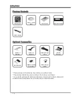
Page 12: ...otice The packing contents may vary according to the model you purchased If you need to purchase the optional accessories or request part numbers please visit the MSI website at http www msi com index...

Page 13: ...handling the mainboard to prevent electrostatic damage If an ESD wrist strap is not available discharge yourself of static electricity by touching another metal object before han dling the mainboard S...

Page 14: ...ATA 6Gb s port SATA1 by Intel B75 5x SATA 3Gb s ports SATA2 6 by Intel B75 USB 3 0 2x USB 3 0 rear IO ports by Intel B75 1x USB 3 0 onboard connector by Intel B75 Multi GPU Supports ATI CrossFireTM Te...

Page 15: ...0 x16 speed PCI_E2 supports up to PCIe 3 0 x4 speed 2x PCI slot Form Factor Micro ATX 24 4 cm X 24 4 cm Mounting Screw Holes 8x mounting holes For the latest information about CPU please visit http w...

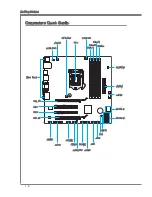
Page 16: ...Connectors Quick Guide CPU CPUFAN DIMM1 JPWR2 JPWR1 SATA3 6 PCI_E1 SYSFAN1 JBAT1 SYSFAN2 JCOM1 PCI_E2 JFP2 JTPM1 JUSB3 SATA1 2 DIMM2 DIMM3 DIMM4 PCI1 JFP1 JCI1 JUSB2 JUSB1 JLPT1 JAUD1 JUSB_PW2 JUSB_P...

Page 17: ...26 JCOM1 Serial Port Connector 1 28 JFP1 JFP2 Front Panel Connectors 1 24 JLPT1 Parallel Port Connector 1 28 JPWR1 ATX 24 pin Power Connector 1 15 JPWR2 ATX 4 pin Power Connector 1 15 JTPM1 TPM Module...

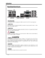
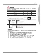
Page 18: ...3 0 compliant HDMI Port The High Definition Multimedia Interface HDMI is an all digital audio video interface that is capable of transmitting uncompressed streams HDMI supports all types of TV format...

Page 19: ...er is communicating with another computer on the network Right Green Off 10 Mbits sec data rate On 100 Mbits sec data rate Orange On 1000 Mbits sec data rate Audio Ports These connectors are used for...

Page 20: ...t the CPU from overheating Be sure to apply an even layer of thermal paste or thermal tape between the CPU and the heatsink to enhance heat dissipation Replacing the CPU When replacing the CPU always...

Page 21: ...ainboard Unhook and lift the loading lever to the fully open position 1 The loading plate should automatically lift up as the loading lever is pushed to the fully open position Do not touch any of the...

Page 22: ...ion tab 5 Evenly spread a thin layer of thermal paste or thermal tape on the top of the CPU This will help in heat dissipation and prevent CPU overheating 6 Locate the CPU fan connector on the mainboa...

Page 23: ...refer to the documentation in the CPU cooler package for more details about CPU cooler installation Push down on the heatsink until the four clips get wedged into the holes on the mainboard Press the...

Page 24: ...re the mainboard with the screws provided with your computer case The locations of the screw holes on the mainboard are shown below For more information please refer to the manual that came with the c...

Page 25: ...power connector 1 3 3 3 V 1 3 3 V 1 4 1 2 V 2 3 3 V 1 5 G r o u n d 3 G r o u n d 1 6 P S O N 4 5 V 1 7 G r o u n d 5 G r o u n d 1 8 G r o u n d 6 5 V 1 9 G r o u n d 7 G r o u n d 2 2 5 V 1 0 1 2 V...

Page 26: ...can enhance system performance The following illustrations explain the population rules for Dual Channel mode 1 DIMM1 DIMM2 DIMM3 DIMM4 2 DIMM1 DIMM2 DIMM3 DIMM4 Important DDR3 memory modules are not...

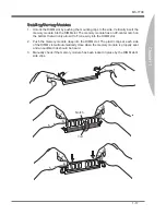
Page 27: ...ff center notch on the bottom that will only allow it to fit one way into the DIMM slot Push the memory module deep into the DIMM slot The plastic clips at each side of the DIMM slot will automaticall...

Page 28: ...Ie 3 0 x16 Slot PCIe 2 0 x1 Slot PCI Peripheral Component Interconnect Slot The PCI slot supports additional LAN SCSI USB and other add on cards that comply with PCI specifications 32 bit PCI Slot Imp...

Page 29: ...I graphics cards are recommended Single Video Card Installation Determine what type of expansion slot s the video card will use Locate the expan sion slot s on the mainboard Remove any protective expa...

Page 30: ...Link cable are required to connect the graphics cards Attach one side of the cable on each of the cards by way of the metal contacts please refer to the picture below Please note that although two gra...

Page 31: ...ing the operating system OS right click on the desktop and choose the Catalyst Control Center II 3 4 The CrossFire setting must be enabled to allow CrossFire mode to operate The follow screen appears...

Page 32: ...supply Such devices include disk drives HDD solid state drives SSD and optical drives CD DVD Blu Ray Please refer to the device s manual for further information Many computer cases also require that...

Page 33: ...ector SYSFAN2 1 G r o u n d 2 1 2 V 3 S e n s o r 4 C o n t r o l CPUFAN SYSFAN1 1 G r o u n d 2 1 2 V 3 S e n s o r 4 N o U s e 1 G r o u n d 2 1 2 V 3 N o U s e Important Please refer to your proces...

Page 34: ...en plug the mConnectors into the mainboard 1 3 1 0 N o P i n 5 R e s e t S w i t c h H D D L E D P o w e r S w i t c h P o w e r L E D 7 9 R e s e r v e d 8 6 4 2 JFP1 1 G r o u n d 3 S u s p e n d L...

Page 35: ...7 G r o u n d 6 U S B 3 _ T X _ C _ D P 2 0 N o P i n 1 9 P o w e r 1 8 U S B 3 _ R X _ D N 1 7 U S B 3 _ R X _ D P 1 6 G r o u n d 1 5 U S B 3 _ T X _ C _ D N 1 4 U S B 3 _ T X _ C _ D P 1 3 G r o u...

Page 36: ...ayout in this figure is for reference only USB 2 0 Bracket optional Important Note that the VCC and GND pins must be connected correctly to avoid possible damage JCI1 Chassis Intrusion Connector This...

Page 37: ...N C 2 G r o u n d JTPM1 TPM Module Connector This connector connects to a TPM Trusted Platform Module Please refer to the TPM security platform manual for more details and usages The MB layout in this...

Page 38: ...connect an optional parallel port bracket The parallel port is a standard printer port that supports Enhanced Parallel Port EPP and Extended Capabilities Parallel Port ECP mode 1 0 G r o u n d 1 4 G r...

Page 39: ...de power in standby mode Close 1 2 Keep USB power to VCC5 default for back panel USB connectors 1 Close 2 3 Keep USB power to 5VSB 1 JUSB_PW1 Close 1 2 Keep USB power to VCC5 default for on board USB...

Page 40: ...system can automatically boot into the operating system OS every time it is turned on If you want to clear the system configuration set the jumpers to clear the CMOS RAM Keep Data Clear Data 1 1 Impor...

Page 41: ...onitor CPU temperature select the boot device priority and view system information such as the CPU name DRAM capacity the OS version and the BIOS version Users can import and export parameter data for...

Page 42: ...he items under each BIOS category described in this chapter are under continuous update for better system performance Therefore the description may be slightly differ ent from the latest BIOS and shou...

Page 43: ...ed to keep unauthorized people from mak ing any changes to the settings You can use these security features to protect your system Boot device priority bar You can move the device icons to change the...

Page 44: ...s F5 Enter Memory Z F6 Load optimized defaults F8 OC Profile Load From USB F9 OC Profile Save to USB F10 Save Change and Reset F12 Save a screenshot to a FAT FAT32 USB drive Sub Menu If you find a poi...

Page 45: ...can be keyed by numeric function keys year The year can be adjusted by users System Time This allows you to set the system time that you want usually the current time The time format is hour minute s...

Page 46: ...indicate the sleep suspend state Blinking The power LED blinks to indicate the sleep suspend state Integrated Peripherals Press Enter to enter the sub menu Onboard LAN Controller This item allows you...

Page 47: ...ares memory to the onboard graphics This setting controls the exact memory size shared to the onboard graphics DVMT Memory Specify the size of DVMT memory to allocate for video memory IGD Multi Monito...

Page 48: ...CPU FAN SYS FAN 1 2 Speed These items show the current status of all of the monitored hardware devices com ponents such as CPU temperature system temperature and the few fans speeds Intel R Smart Con...

Page 49: ...S3 by USB Device The item allows the activity of the USB device to wake up the system from S3 Sus pend to RAM sleep state Resume From S3 S4 S5 by PS 2 Mouse Keyboard These items determine whether the...

Page 50: ...used to abandon all changes Restore Defaults This item is used to load the optimized default values set by the BIOS vendor Boot Override The installed storage devices will appear on this menu you can...

Page 51: ...the processor This feature can only be changed if the processor supports this function Adjusted CPU Frequency It shows the adjusted CPU frequency Read only Adjust CPU Ratio in OS Enable this item to a...

Page 52: ...verclocking behavior is not guaranteed Adjusted DRAM Frequency It shows the adjusted DRAM frequency Read only DRAM Timing Mode Select whether DRAM timing is controlled by the SPD Serial Presence Detec...

Page 53: ...mand starts tRRD Specifies the active to active delay of different banks tRTP Time interval between a read and a precharge command tFAW This item is used to set the tFAW four activate window delay tim...

Page 54: ...Read only Overclocking Profiles Press Enter to enter the sub menu Overclocking Profile 1 2 3 4 5 6 Press Enter to enter the sub menu Set Name for Overclocking Profile 1 2 3 4 5 6 Give a name by typing...

Page 55: ...ned to limit the listed speed of the processor to older operating systems Execute Disable Bit Can prevent certain classes of malicious buffer overflow attacks where worms can try to execute code to da...

Page 56: ...taining time for long duration power limit Short duration power limit W This field allows you to adjust the TDP power limit for the short duration Primary Secondary Plane Current value A These fields...

Page 57: ...will not support RTC wake up event functions C1E Support To enable this item to reduce the CPU power consumption while idle Not all processors support Enhanced Halt state C1E Intel C State C state is...

Page 58: ...WSER to access the Internet e mail and instant messaging Installing Winki To install Winki follow the steps below Power on your computer and enter Windows operating system Insert MSI Driver Disc into...

Page 59: ...button on the BIOS UTILITIES menu The Winki must be installed 1 Setup the connection by click the setting button if necessary Click the next button Live Update will automatically detect the version o...

Page 60: ...D with single partition only the requirements for HDD Backup are An additional partition from another HDD ex USB HDD for HDD Backup to back up restore image to from it Executing Winki stored in USB fl...

Page 61: ...item allows to select particular BIOS file from the USB Storage FAT 32 format only drive And the system will boot from selected BIOS file Save BIOS to storage Please setup a specific folder in specifi...

Page 62: ...rd press Enter when you are prompted to enter a new pass word A message will confirm the password is being disabled Once the password is disabled you can enter the setup and OS without authorization U...

Page 63: ...The Realtek audio provides 8 channel DAC that support 7 1 sound playback Appendix A Realtek Audio...

Page 64: ...ly different if you install the drivers in different operating systems Insert the application DVD into the DVD ROM drive The setup screen will automati cally appear Click Driver tab Click AUDIO button...

Page 65: ...may double click the icon and the GUI will pop up accordingly double click the icon It is also available to enable the audio driver by clicking the Realtek HD Audio Manager from the Control Panel Sof...

Page 66: ...e bar Application Enhancement The array of options will provide you a complete guidance of anticipated sound effect for both output and input device Jack status panel This panel depicts all render and...

Page 67: ...pendix A Hardware Default Setting The following diagrams are audio back panel default setting Backpanel audio jacks to 2 channel speakers diagram Front Backpanel audio jacks to 4 channel speakers diag...

Page 68: ...A 6 Realtek Audio Backpanel audio jacks to 6 channel speakers diagram Rear Front Center Subwoofer Backpanel audio jacks to 8 channel speakers diagram Rear Front Center Subwoofer Side Surround...

Page 69: ...Intel SBA provides an out of the box hardware based security and produc tivity suite designed for the small business user Intel SBA includes a customizable user interface and several bundled Intel app...

Page 70: ...PC Health Center task cannot be enabled This means that the end user cannot use PC Health Center to manage Windows Update To prevent this make sure that you do NOT select the Never check for updates...

Page 71: ...pear Click OTHERS tab Select Intel SBA to start installing Follow the on screen instructions to install Software Configuration After installation of the Intel SBA software is complete the Intel SBA se...

Page 72: ...menu of the GUI Fill out the form to create the new password and click Save You will be asked to enter the password when you want to start using Intel SBA Important Upon completion of the password se...

Page 73: ...This chapter describes how to install Windows XP with IDE or AHCI mode Appendix C Install Windows XP Notes...

Page 74: ...rted to be installed in the storage device with AHCI mode If you still prefer to install Windows XP as the operating system please change the BIOS item as below Refer to Chapter 2 to access BIOS Go to...

Page 75: ...nload the driver from http download3 msi com files downloads dvr_exe intel7x_rst_floppy_mb zip Installing the Windows XP Operating System Please follow the below steps Access BIOS set SATA Mode to AHC...

Page 76: ......

Reviews: