background image

3-3

BIOS Setup

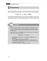
Getting Help

After entering the Setup menu, the first menu you will see is the


Main Menu.

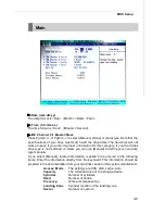
Main  Menu

The main menu lists the setup functions you can make changes to. You can use the
arrow keys ( 

↑↓ ) 

to select the item. The on-line description of the highlighted setup

function is displayed at the bottom of the screen.

Su b-Menu

If you find a right pointer symbol  (as shown in the right  view)
appears to the left of certain fields that means a sub-menu can
be launched from this field. A sub-menu contains additional op-
tions for a field parameter. You can use  arrow keys  ( 

↑↓ )

 to

highlight the field and press <Enter> to call up the sub-menu. Then you can use the
control keys to enter values  and  move from field to field within a sub-menu. If you
want to return to the main menu, just press the <Esc >.

General Help <F1>

The BIOS setup program provides a General  Help screen. You can call up this screen
from any menu by simply pressing <F1>. The Help screen lists the appropriate keys
to use and the possible selections for the highlighted item. Press <Esc> to exit the
Help screen.

Control Keys

<

>

Move to the previous item

<

>

Move to the next item

<

>

Move to the item in the left hand

<

>

Move to the item in the right hand

<Enter>

Select the item

<Esc>

Jumps to the Exit menu or returns to the main menu from a

submenu

<+/PU>

Increase the numeric value or make changes

<-/PD>

Decrease the numeric value or make changes

<F6>

Load Optimized Defaults

<F7>

Load Fail-Safe Defaults

<F10>

Save all the CMOS changes and exit

Summary of Contents for MS-9642

Page 1: ...i MS 9642 V3 X Mainboard G52 96421X4 Fuzzy 945GME3...

Page 2: ...s and or other countries PS 2 and OS 2 are registered trademarks of International Business Machines Corporation Windows 98 2000 NT XP Vista are registered trademarks of Microsoft Corporation Netware i...

Page 3: ...inserting any add on card or module 9 All cautions and warnings on the equipment should be noted 10 Never pour any liquid into the opening that could damage or cause electrical shock 11 If any of the...

Page 4: ...interference by one or more of the measures listed below Reorient or relocate the receiving antenna Increase the separation between the equipment and receiver Connect the equipment into an outlet on...

Page 5: ...v WEEE Waste Electrical and Electronic Equipment Statement...

Page 6: ...vi...

Page 7: ...vii...

Page 8: ...ion 1 6 Back Panel I O Shield Drawing 1 7 Power Consumption 1 8 Safety Compliance MTBF 1 9 Chapter 2 Hardware Setup 2 1 Quick ComponentsGuide 2 2 CPU Central Processing Unit 2 3 Memory 2 6 Power Suppl...

Page 9: ...945GME3 accommodates the latest Intel Core 2 Duo Core Duo Core Solo Celeron M Celeron LV 423 BGA with BGA Passive Cooler processors in Socket M and supports one 240 pin 533 667MHz DDR2 DIMM slot to p...

Page 10: ...h Bridge Intel 945GM 945GME chipset South Bridge Intel ICH7M chipset Memory DDR2 533 667 SDRAM 2GB Max 1 DDR2 DIMM slot 240pin 1 8V LAN Supports 2 PCI Express Gb Ethernet by Intel 82573L Audio HDA Cod...

Page 11: ...2 ports 1 parallel port pinheader 1 front audio pinheader 1 LVDS connector 1 Digital I O pinheader 16 GPIO 4 RS232 pinheaders as COM1 COM4 optional 1 front panel pinheader Slots 1 PCI Express x16 slo...

Page 12: ...MS 9642 Mainboard 1 4 Block Diagram...

Page 13: ...AUD1 JAMP1 J6 J3 J5 J7 PCI1 IDE1 SATA1 SATA2 F_USB2 CPUFAN1 JFP1 JLVDS1 Top Mouse Bottom Keyboard Top Serial Port Bottom VGA Port USB Ports LAN Jacks JLPT1 JCI1 SYSFAN1 SYSFAN2 CLR_CMOS1 J 1 J8 BATT T...

Page 14: ...MS 9642 Mainboard 1 6 Board Dimension...

Page 15: ...1 7 Getting Started Back Panel I O Shield Drawing...

Page 16: ...HITACHI 20G 1 8 12V 5V 3 3V 12V 5Vsb Power W 3D Maker 2006 2 17 2 77 0 71 0 054 0 066 43 211 CPU Stress 2 35 2 32 0 68 0 035 0 066 42 794 Enter DOS 1 57 1 62 0 66 0 048 0 055 29 969 Enter BIOS 1 63 1...

Page 17: ...voltage fluctuation and flicker in low voltage supply system Immunity EN 55024 1998 A1 2001 A2 2003 Product family standard BSMI C Tick CE RFI VCCI VCCI V 3 2004 Class B VCCI V 4 2004 Class B Standard...

Page 18: ...MS 9642 Mainboard 1 10...

Page 19: ...dures While doing the installation be careful in holding the components and follow the installation procedures For some components if you install in the wrong orientation the components will not work...

Page 20: ...2 9 J4 p 2 17 DIMM Slot p 2 6 JCI1 p 2 9 JLPT1 p 2 15 Back Panel I O p 2 8 CPUFAN1 p 2 12 J3 p 2 15 JFP1 p 2 12 CLR_CMOS1 p 2 17 PCI Slot p 2 18 F_USB2 p 2 14 PCI E Slot p 2 18 JLVDS1 p 2 16 SATA1 2...

Page 21: ...e replacing the CPU always turn off the power supply or unplug the power supply s power cord from the grounded outlet first to ensure the safety of CPU The mainboard supports Intel Core 2 Duo Core Duo...

Page 22: ...e CPU down until its pins securely fit into the socket CPU Cooler Set Installation 3 On the front end of the CPU socket is a locking mechanism designed into the form of a screw Make sure that you actu...

Page 23: ...t fan heatsink bundled on top of the CPU and fit it into the retention mechanism 7 Connect the fan power cable from the mounted fan to the 3 pin fan power con nector on the mainboard 6 Secure the meta...

Page 24: ...lot Then push it in until the golden finger on the memory module is deeply inserted in the DIMM slot 3 The plastic clip at each side of the DIMM slot will automatically close Important You can barely...

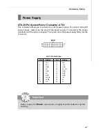
Page 25: ...18 5V 19 5V 20 5V PIN SIGNAL 1 3 3V 2 3 3V 3 GND 4 5V 5 GND 6 5V 7 GND 8 PW_OK 9 5V_SB 10 12V ATX 20 Pin System Power Connector ATX1 This connector allows you to connect to an ATX power supply To conn...

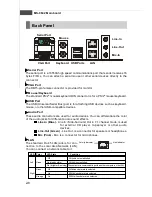
Page 26: ...the color of the audio jacks for different audio sound effects Line In Blue Line In Side Surround Out in 7 1 channel mode is used for external CD player tapeplayer or other audio devices Line Out Gree...

Page 27: ...sis Intrusion Connector JCI1 This connector connects to the chassis intrusion switch cable If the chassis is opened the chassis intrusion mechanism will be activated The system will record this status...

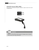
Page 28: ...ot fold the Serial ATA cable into 90 degree angle Otherwise data loss may occur during transmission SATA1 SATA2 Serial ATA Connector SATA1 SATA2 This connector is a high speed Serial ATA interface por...

Page 29: ...udio Amplifier Connector JAMP1 The JAMP1 is used to connect audio amplifiers to enhance audio performance 1 JAMP1 PIN SIGNAL 1 AMP_L 2 AMP_L 3 AMP_R 4 AMP_R Pin Definition 1 2 13 14 JAUD1 PIN SIGNAL P...

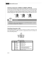
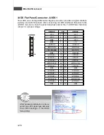
Page 30: ...ant with Intel Front Panel I O Connectivity Design Guide 1 2 9 10 JFP1 HDD LED Reset Switch Power LED Power Switch Fan Power Connector CPUFAN1 SYSFAN1 SYSFAN2 The fan power connectors support system c...

Page 31: ...rt bracket PIN SIGNAL DESCRIPTION 1 DCD DataCarry Detect 2 SIN Serial Inor Receive Data 3 SOUT Serial Outor Transmit Data 4 DTR DataTerminal Ready 5 GND Ground 6 DSR DataSetReady 7 RTS Request ToSend...

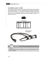
Page 32: ...um throughput of 480Mbps which is 40 times faster than USB 1 1 and is ideal for connecting high speed USB interface peripherals such as USB HDD digital cameras MP3 players printers mo dems and the lik...

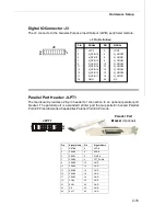
Page 33: ...LPT_SLIN 9 PRND3 10 GND 11 PRND4 12 GND 13 PRND5 14 GND 15 PRND6 16 GND 17 PRND7 18 GND 19 ACK 20 GND 21 BUSY 22 GND 23 PE 24 GND 25 SLCT 26 GND 2 1 26 25 JLPT1 Digital IO Connector J3 The J3 connect...

Page 34: ...1 LVDS B1 LVDS B2 34 33 LVDS B2 LVDS BCLK 36 35 LVDS BCLK LVDS B3 38 37 LVDS B3 GND 40 39 GND LVDS Flat Panel Connector JLVDS1 The LVDS Low Voltage Differential Signal connector provides a digital int...

Page 35: ...lear data Important You can clear CMOS by shorting 1 2 pin while the system is off Then return to 2 3 pin position Avoid clearing the CMOS while the system is on it will damage the mainboard Keep Data...

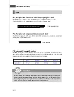
Page 36: ...Q are hardware lines over which devices can send interrupt signals to the microprocessor The PCI IRQ pins are typically connected to the PCI bus pins as follows Order 1 Order 2 Order 3 Order 4 32 bit...

Page 37: ...IOS Setup program and allows you to configure the system for optimum use You may need to run the Setup program when An error message appears on the screen during the system booting up and requests you...

Page 38: ...PHOENIX 2nd 5th digit refers to the model number 6th digit refers to the chipset as I Intel N nVidia and V VIA 7th 8th digit refers to the customer as MS all standard customers V1 0 refers to the BIOS...

Page 39: ...Then you can use the control keys to enter values and move from field to field within a sub menu If you want to return to the main menu just press the Esc General Help F1 The BIOS setup program provid...

Page 40: ...r system s chipset PC Health This entry monitors your hardware health status Security Use this menu to set Supervisor and User Passwords System This entry shows your system summary Boot Use this menu...

Page 41: ...ive type is not matched or listed you can use Manual to define your own drive type manually If you select Manual related information is asked to be entered to the following items Enter the information...

Page 42: ...t will halt on for 15 seconds and then automatically resume its operation Available options are All Errors The system stops when any error is detected No Errors The system doesn t stop for any detecte...

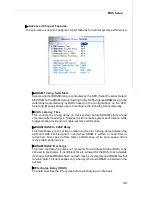
Page 43: ...dvanced Advanced BIOS Features The sub menu is used to configure chipset features for optimal system performance Quick Power On Self Test Select Enabled to reduce the amount of time required to run th...

Page 44: ...tic Rate Setting is enabled this item allows you to set the rate characters second at which the keys are accelerated Typematic Delay Msec This item allows you to select the delay between when the key...

Page 45: ...rease system performance while bigger clocks provide more stable system performance DRAM RAS to CAS Delay This field allows you to set the number of cycles for a timing delay between the CAS and RAS s...

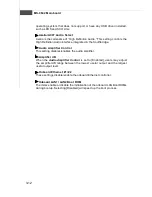
Page 46: ...g the PCI Express graph ics card if one is installed Otherwise it defaults to the onboard graphics processor When set to Auto the BIOS checks to see if a PCI Express graphics card is installed If it d...

Page 47: ...roller This setting is used to enable disable the onboard USB controller USB 2 0 Controller This setting is used to enable disable the onboard USB 2 0 controller USB Keyboard Mouse Support Set to Enab...

Page 48: ...plifier Control This setting disables enables the audio amplifier Amplifier dB When the Audio Amplifier Control is set to Enabled users may adjust the amplifier dB range between the lowest useful outp...

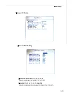
Page 49: ...OS Setup Super IO Device Serial Port Setting Onboard Serial Port 1 2 3 4 5 Select an address for Serial Port 1 2 3 4 5 Serial Port 1 2 3 4 5 Use IRQ Select a corresponding interrupt for Serial Port 1...

Page 50: ...n the EPP mode simultaneously choose EPP By choosing ECP the onboard parallel port will operate in ECP mode only Choosing ECP EPP will allow the onboard parallel port to support both the ECP and EPP m...

Page 51: ...n this state no system context is lost CPU or chipset and hard ware maintains all system context S3 STR The S3 sleep mode is a lower power state where the information of system configuration and open...

Page 52: ...hen Resume By Alarm is set to Enabled the field specifies the month for Resume By Alarm Time hh mm ss Alarm You can choose what hour minute and second the system will boot up PWRON After PWR Fail This...

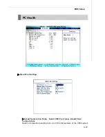
Page 53: ...3 17 BIOS Setup PC Health Smart Fan Setting Smart System Fan Temp Smart CPU Fan Temp Smart Fan3 Temperature Select a temperature setting here and if the temperature of the CPU system...

Page 54: ...ach the maximum threshold the temperatures set in previous settings plus the tolerance values you set here the fans will speed up for cooling down On the contrary if the current temperatures reach the...

Page 55: ...ls access to the system at boot Security Option This specifies the type of BIOS password protection that is implemented Settings are described below Option Description Setup The password prompt appear...

Page 56: ...Mainboard System Machine Type Model Processor Processor Cache Size Processor Speed System Memory Type Video Controller BIOS Date BIOS Version These items show the hardware specifications of your syst...

Page 57: ...elect the desired device then press or PageUp PageDown key to move it up down in the priority list First Second Third Boot Device The items allow you to set the sequence of boot devices where BIOS att...

Page 58: ...BIOS vendor for stable system performance Load Optimized Defaults Use this menu to load the default values set by the mainboard manufacturer specifi cally for optimal performance of the mainboard Sav...

Page 59: ...urces Chapter 4 System Resources This chapter provides information on the following system resources 1 Watch Dog Timer Setting p 4 2 2 Award POST Code p 4 4 3 Check Point Beep Code List p 4 10 4 Resou...

Page 60: ...tch_Dog_Cmos_bits jz F jump if disable mov dx 04Eh Enter config mov al 087h out dx al NEWIODELAY out dx al NEWIODELAY mov al 07h Logical Device 8 mov dx 04Eh out dx al NEWIODELAY mov ax 08h inc dx out...

Page 61: ...GROUP WD_Timer_Item call F000_GetItem_Value mov ah al mov al 0F6h Set time mov dx 04Eh out dx al NEWIODELAY mov al ah fill time 9641_046 inc dx out dx al NEWIODELAY mov dx 04Eh Exit config mov al 0AAh...

Page 62: ...lled correctly If no floppy drives are installed be sure the Diskette Drive selection in Setup is set to NONE or AUTO system board 5 HARD DISK initializing Please wait a moment Some hard drives requir...

Page 63: ...IMM s are in matched pairs C3h Expand compressed BIOS code to DRAM C5h Call chipset hook to copy BIOS back to E000 F000 shadow RAM 01h Expand the Xgroup codes locating in physical address 1000 0 02h R...

Page 64: ...M_INIT switch 1Eh Reserved 1Fh Load keyboard matrix notebook platform 20h Reserved 21h HPM initialization notebook platform 22h Reserved 23h 1 Check validity of RTC value e g a value of 5Ah is an inva...

Page 65: ...for channel 1 3Fh Reserved 40h Test 8259 interrupt mask bits for channel 2 41h Reserved 42h Reserved 43h Test 8259 functionality 44h Reserved 45h Reserved 46h Reserved 47h Initialize EISA slot 48h Res...

Page 66: ...until this POST stage can users enter the CMOS setup utility 61h Reserved 62h Reserved 63h Reserved 64h Reserved 65h Initialize PS 2 Mouse 66h Reserved 67h Prepare memory size information for function...

Page 67: ...1 USB final Initialization 2 NET PC Build SYSID structure 3 Switch screen back to text mode 4 Set up ACPI table at top of memory 5 Invoke ISA adapter ROMs 6 Assign IRQs to PCI devices 7 Initialize APM...

Page 68: ...ROM to lower system memory and control is given to it BIOS now executes out of RAM Copies compressed boot block code to memory in right segments Copies BIOS from ROM to RAM for faster access Performs...

Page 69: ...t directory F1 Recovery file not found F2 Start reading FAT table and analyze FAT to find the clusters occupied by the recovery file F3 Start reading the recovery file cluster by cluster F5 Disable L1...

Page 70: ...aps INT1Ch vector to POSTINT1ChHandlerBlock 07 Fixes CPU POST interface calling pointer 08 Initializes the CPU The BAT test is being done on KBC Program the keyboard controller command byte is being d...

Page 71: ...system Also Check for DEL or ESC keys to limit memory test Display total memory in the system 3C Mid POST initialization of chipset registers 40 Detect different devices Parallel ports serial ports a...

Page 72: ...es the system configuration display if needed A4 Initialize runtime language module Display boot option popup menu A7 Displays the system configuration screen if enabled Initialize the CPU s before bo...

Page 73: ...h Program error 12 AMIBOOT ROM file size error 13 BIOS ROM image mismatch file layout does not match image present in flash device POST BIOS Beep Codes Number of Beeps Description 1 Memory refresh tim...

Page 74: ...all expansion cards except the video adapter If beep codes are generated when all other expansion cards are absent consult your system manufacturer s technical support If beep codes are not generated...

Page 75: ...2 I NC VCCSUS3P3 LAN3_EN E19 13 I NC VCCSUS3P3 SIO_PME R4 14 I NC VCCSUS3P3 VCC3V_SB E22 15 O NC VCCSUS3P3 AT ATX SELECT AC22 16 O DPRSLPVR VCC3P3 DPRSLPVR D8 17 O PCIGNT5 VCC3P3 NC AC20 18 O STPPCI V...

Page 76: ...EN VCC3P3 AUXGPIO_DIR1 U2 34 O AZ_DOCK_RST VCC3P3 AUXGPIO_DIR2 AD21 35 O SATACLKREQ VCC3P3 NC AH19 36 I SATA2GP VCC3P3 AMP_GAIN1 AE19 37 I SATA3GP VCC3P3 NC AD20 38 O NC VCC3P3 AUXGPIO_OE AE20 39 O NC...

Page 77: ...21 GPIO22 19 IO VCC NC GPIO23 2 IO VCC NC GPIO24 66 IO VSB MSDAT GPIO25 65 IO VSB MSCLK GPIO26 63 IO VSB KBDAT GPIO27 62 IO VSB KBCLK GPIO30 92 IO VSB AUXGPIO20 GPIO31 91 IO VSB AUXGPIO21 GPIO32 90 I...

Page 78: ...53 72 O VSB PS_ON GPIO54 71 IO VSB NC GPIO55 70 IO VSB NC GPIO56 68 I VSB PWRBTIN GPIO57 67 O VSB PWRBTN GPIO60 57 IO VCC RIA GPIO61 56 IO VCC DCDA GPIO62 54 IO VCC SOUTA GPIO63 53 IO VCC SINA GPIO64...

Page 79: ...nd CMOS 0080 0090 DMA Controller Page Registers 0092 Port 92h 00A0 00A1 Interrupt Controller 2 00B2 00B3 APM register 00C0 00DF DMA Controller 2 00F0 00FF Numeric Data Processor 01F0 01F7 Primary IDE...

Page 80: ...MS 9642 Mainboard 4 22 PCI Devices...

Page 81: ...iption MS 7 0101 111X MSI ACPI Controller DIMM Slot 1010 0000 SPD IRQ Description IRQ0 System Timer IRQ1 Keyboard Controller IRQ2 Second 8259A IRQ3 COM2 COM4 IRQ4 COM1 COM3 IRQ5 LPT2 IRQ6 Floppy Disk...

Reviews: