background image

3-12

BIOS SETUP

b

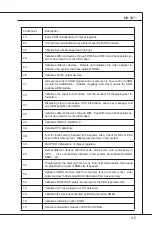
oot

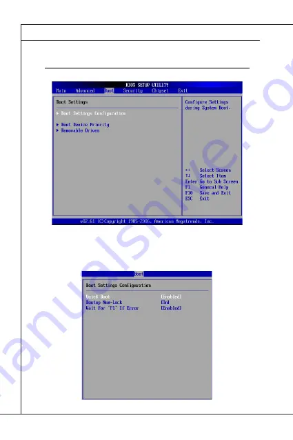
Boot Settings Configuration

Summary of Contents for MS-9871

Page 1: ...IMGS45 M MS 9871 v1 x Industrial Computer Board...

Page 2: ...s of Microsoft Corporation AMI is registered trademark of Advanced Micro Devices Inc Award is a registered trademark of Phoenix Technologies Ltd Sound Blaster is registered trademark of Creative Techn...

Page 3: ...s on the equipment should be noted Never pour any liquid into the opening that could damage or cause electrical shock If any of the following situations arises get the equipment checked by service per...

Page 4: ...e interference by one or more of the measures listed below Reorient or relocate the receiving antenna Increase the separation between the equipment and receiver Connect the equipment into an outlet on...

Page 5: ...tger te nicht mehr als kommunale Abf lle entsorgt werden MSI hat europaweit verschiedene Sammel und Recyclingunternehmen beauftragt die in die Eu rop ische Union in Verkehr gebrachten Produkte am Ende...

Page 6: ...oducten die de merknaam MSI dragen en verkocht zijn in de EU Deze goederen kunnen geretourneerd worden op lokale inza melingspunten SRPSKI Da bi za titili prirodnu sredinu i kao preduze e koje vodi ra...

Page 7: ...sb rn ch MAGYAR Annak rdek ben hogy k rnyezet nket megv dj k illetve k rnyezetv d k nt fell pve az MSI eml kezteti nt hogy Az Eur pai Uni EU 2005 augusztus 13 n hat lyba l p az elektromos s elek troni...

Page 8: ...1 Overview 1 1 Mainboard Specifications 1 2 Mainboard Layout 4 Block Diagram 1 6 Chapter 2 Hardware Setup 2 1 Quick Components Guide 2 2 Memory 2 4 Power Supply 2 5 Back Panel I O 2 6 Connector 2 8 Ju...

Page 9: ...odates the latest Intel Core 2 Duo SL9400 SP9300 SU9600 optional SU9300 SU7300 optional SU3500 ULV722 ULV723 proces sors and supports up to 2 DDR2 667 800 SO DIMM slots to pro vide the maximum of 4GB...

Page 10: ...Cache 1 20 GHz 800 MHz FSB Intel Core 2 Duo processor SU9600 3M Cache 1 60 GHz 800 MHz FSB optional Intel Core 2 Duo processor SU7300 3M Cache 1 30 GHz 800 MHz FSB optional Chipset North Bridge Intel...

Page 11: ...connectors supports 10 ports 1 SPI Flash ROM pinheader for debugging 1 LVDS connector 1 chassis intrusion connector 1 amplifier pinheader 1 VGA port connector 1 port 1 HDMI port connector 2 ports 1 D...

Page 12: ...board Layout JRTC1 JCOMP1 JCOMP2 JSPI JLVDS1 J1 JBAT1 JCOMP4 JAMP1 JCASE1 JCOMP3 JUSB1 JLPC1 MINI_PCIE1 COM7 10 COM3 COM2 JPW1 CPUFAN1 SYSFAN1 JFP1 COM1 SATA1 SATA2 JHDDPWR1 JVGA1 JHDMI1 JDVI1 SLOT1 J...

Page 13: ...1 5 MS 9871 MINI_PCIE2 DIMM2 Back Side...

Page 14: ...VI HDMI 2 DVI 2 VGA 1 Level Shift Level Shift MXM 3 0 slot DDR2 667 800 2 x SO DIMM Intel ICH9M SFF 6 USB 2 0 Ports AMI BIOS 2 Mini PCIE slots 2 SATA Ports SPI Realtek ALC888 Intel 82574L GbE LAN Inte...

Page 15: ...d hardware configurations Incorrect setting of jumpers and connectors may damage your main board Please pay special attention not to connect these headers in wrong direction DO NOT adjust any jumper w...

Page 16: ...2 17 MINI_PCIE1 p 2 18 JCOMP4 p 2 17 Back Panel I O p 2 6 JLVDS1 p 2 11 JCOMP1 JCOMP2 p 2 17 COM3_6 p 2 13 JPW1 p 2 5 JSPI1 p 2 14 SLOT1 p 2 15 JFP1 p 2 10 SATA1 2 p 2 9 JVGA1 p 2 16 Front Side JDVI1...

Page 17: ...2 3 MS 9871 Back Side MINI_PCIE2 DIMM2 DIMM2 p 2 4 MINI_PCIE2 p 2 18...

Page 18: ...DIMM gently forwards until the slot levers click and lock the DIMM in place Follow the same procedures to install the second DIMM if necessary To uninstall the DIMM flip the slot levers outwards and t...

Page 19: ...system and CPU HDD Power Connector JHDDPWR1 This connector provides power to the hard disk drive Important Power supply of 200watts and above is highly recommended for system stability Power Supply 1...

Page 20: ...tegrated connector allows you to con nect an LCD monitor It provides a high speed digital interconnection be tween the computer and its display device To connect an LCD monitor simply plug your monito...

Page 21: ...OFF Transmission Green Blinking OFF 100M Cable Plug in No Transmission Green Lighting Green Lighting Transmission Green Blinking Green Lighting 1000M Cable Plug in No Transmission Green Lighting Yell...

Page 22: ...s Ground and should be connected to GND If the mainboard has a System Hardware Monitor chipset onboard you must use a specially designed fan with speed sensor to take advantage of the CPU fan control...

Page 23: ...into 90 degree angle Otherwise data loss may occur during transmission Chassis Intrusion Connector JCASE1 This connector is provided to connect the chassis intrusion switch cable If the chassis is op...

Page 24: ...1 2 3 4 5 6 7 8 9 10 HD_LED FP PWR SLP HD_LED FP PWR SLP RST_SW PWR_SW RST_SW PWR_SW RSVD_DNU KEY Hard disk LED pull up MSG LED pull up Hard disk active LED MSG LED pull up Reset Switch low reference...

Page 25: ...2 1 39 40 SIGNAL PIN SIGNAL 12V 12V GND GND LCD_VDD LDDC_DATA LVDS_VDDEM GND LA_DATA0 LA_DATA1 LA_DATA2 LA_CLK LA_DATA3 GND LB_DATA0 LB_DATA1 LB_DATA2 LB_CLK LB_DATA3 GND 2 4 6 8 10 12 14 16 18 20 22...

Page 26: ...al for connecting high speed USB interface peripherals such as USB HDD digital cameras MP3 players printers modems and the like USB 2 0 Bracket Optional Important Note that the pins of VCC and GND mus...

Page 27: ...rry Detect Serial In or Receive Data Serial Out or Transmit Data Data Terminal Ready Ground Data Set Ready Request To Send Clear To Send Ring Indicate Key COM1 COM2 PIN SIGNAL PIN SIGNAL PIN SIGNAL PI...

Page 28: ...AL 1 3 5 7 9 11 13 LCLK LPC_RST LAD0 LAD1 LAD2 LAD3 LPC_FRAME 2 4 6 8 10 12 14 3VSB VCC3 SIRQ VCC5 Key no pin GND GND SPI Flash ROM Connector JSPI1 This connector is used to flash SPI flash ROM 1 2 9...

Page 29: ...DMI connector PIN SIGNAL PIN SIGNAL PIN SIGNAL 1 2 3 4 5 6 7 8 9 10 HDMIB_TX2 HDMIA_TX2 HDMIB_TX2 HDMIA_TX2 GND GND HDMIB_TX1 HDMIA_TX1 HDMIB_TX1 HDMIA_TX1 11 12 13 14 15 16 17 18 19 20 GND GND HDMIB_...

Page 30: ...10 DVIB_TX2 DVIA_TX2 DVIB_TX2 DVIA_TX2 GND GND DVIB_TX1 DVIA_TX1 DVIB_TX1 DVIA_TX1 11 12 13 14 15 16 17 18 19 20 GND GND DVIB_TX0 DVIA_TX0 DVIB_TX0 DVIA_TX0 GND GND DVIB_CLK DVIA_CLK 21 22 23 24 25 26...

Page 31: ...ve the system configuration data With the CMOS RAM the system can automatically boot OS every time it is turned on If you want to clear the system configuration set the jumper to clear data Important...

Page 32: ...ardware setup 5V 1 12V 1 JCOMP4 1 Serial Port Power Jumper JCOMP1 4 These jumpers are provided for users to select the operation voltage of the onboard serial ports 5V 1 12V 1 JCOMP1 2 1 5V 1 12V 1 JC...

Page 33: ...ortant When adding or removing expansion cards make sure that you unplug the power supply first Meanwhile read the documentation for the expansion card to configure any necessary hardware or software...

Page 34: ......

Page 35: ...you to configure the system for optimum use You may need to run the Setup program when An error message appears on the screen during the system booting up and requests you to run SETUP You want to ch...

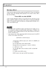
Page 36: ...r each BIOS category described in this chapter are un der continuous update for better system performance Therefore the description may be slightly different from the latest BIOS and should be held fo...

Page 37: ...in the right view appears to the left of certain fields that means a sub menu can be launched from this field A sub menu contains additional options for a field parameter You can use arrow keys to hi...

Page 38: ...es Boot Use this menu to specify the priority of boot devices Security Use this menu to set supervisor and user passwords Chipset This menu controls the advanced features of the onboard Northbridge an...

Page 39: ...ow the firmware and hardware specifications of your system Read only System Time This setting allows you to set the system time The time format is Hour Minute Second System Date This setting allows yo...

Page 40: ...3 6 BIOS SETUP Advanced CPU Configuration...

Page 41: ...mbined with a supporting operating system This functionality allows the processor to classify areas in memory by where application code can execute and where it cannot When a malicious worm attempts t...

Page 42: ...ning message if the chassis is once opened To clear the warning message set the field to Reset The set ting of the field will automatically return to the default value later CPU Smart Fan Target SYS S...

Page 43: ...the system from the S3 sleep state Restore on AC Power Loss This setting specifies whether your system will reboot after a power failure or interrupt occurs Available settings are Power Off Leaves th...

Page 44: ...the system from suspend mode Super IO Configuration Serial Port 1 2 3 4 5 6 7 8 9 Address Select an address for the specified serial port Serial Port 1 2 3 4 5 6 7 8 9 Mode Select an operation mode f...

Page 45: ...by the Trusted Computing Group TCG TPMs are special purpose inte grated circuits ICs built into a variety of platforms to enable strong user authentication and machine attestation essential to preven...

Page 46: ...3 12 BIOS SETUP Boot Boot Settings Configuration...

Page 47: ...n error it asks you to press F1 If disabled the system continues to boot without waiting for you to press any keys Boot Device Priority The items allow you to set the sequence of boot devices where BI...

Page 48: ...pervisor Password controls access to the BIOS Setup utility These set tings allow you to set or change the supervisor password User Password Change User Password User Password controls access to the s...

Page 49: ...graphics processor It is recommended that you set this BIOS feature to DVMT Mode for maxi mum performance Setting it to DVMT Mode ensures that system memory is dynamically allocated for optimal balan...

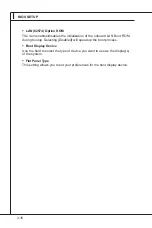
Page 50: ...onboard LAN Boot ROM during bootup Selecting Disabled will speed up the boot process Boot Display Device Use the field to select the type of device you want to use as the display s of the system Flat...

Page 51: ...p Utility Discard Changes Abandon all changes and continue with the Setup Utility Load Optimal Defaults Use this menu to load the default values set by the mainboard manufacturer specifically for opti...

Page 52: ......

Page 53: ...This chapter provides information on the following sys tem resources 1 Watch Dog Timer Setting 2 AMI POST Code 3 Resource List Chapter 4 System Resources...

Page 54: ...nds 1 Enter configuration mode mov dx SIO_IDX mov al 87h out dx al out dx al 2 Set to LDN 07 mov dx SIO_IDX mov al 07h out dx al mov dx SIO_DTA mov al 07h out dx al 3 Set WatchDog Timer mov dx SIO_IDX...

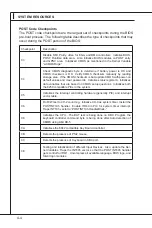
Page 55: ...set initialization Re en able CACHE Verify that flat mode is enabled D4 Test base 512KB memory Adjust policies and cache first 8MB Set stack D5 Bootblock code is copied from ROM to lower system memory...

Page 56: ...Initializes data variables that are based on CMOS setup questions Initializes both the 8259 compatible PICs in the system 05 Initializes the interrupt controlling hardware generally PIC and interrupt...

Page 57: ...on 38 Initializes different devices through DIM See DIM Code Checkpoints sec tion of document for more information 39 Initializes DMAC 1 DMAC 2 3A Initialize RTC date time 3B Test for total memory ins...

Page 58: ...OS modules Fill the free area in F000h segment with 0FFh Initializes the Microsoft IRQ Routing Table Prepares the runtime language module Disables the system configuration display if needed A4 Initial...

Page 59: ...GPIO6 10 0A GPIO7 I PCB version identify 3 3V 0 1 0 0 PCB VER GPIO7 GPIO6 10 0A GPIO8 O USB port power enable pin 1 enable USB port power 0 disable USB port power 3VSB Set to 1 at S0 S3 Set to 0 at S...

Page 60: ...Type Function Power Description 54 GP02 O EN485 Default high for RS232 function 5VSB 55 GP03 O EN232 Default high for RS232 function 5VSB 56 GP04 O EN422 Default high for RS232 function 5VSB 52 GP00 O...

Page 61: ...60 0064 Keyboard Controller 0070 0073 RTC and CMOS 0080 0090 DMA Controller Page Registers 00A0 00A1 Interrupt Controller 2 00B2 00B3 APM Register 00C0 00DF DMA Controller 2 00F0 00FF Numeric Data Pro...

Page 62: ...8 00 1A 02 Intel PCI Bridge 8086 2940 00 1C 00 Intel USB Controller 8086 2934 00 1D 00 Intel USB Controller 8086 2935 00 1D 01 Intel USB Controller 8086 2936 00 1D 02 Intel USB Controller 8086 293A 00...

Page 63: ...COM5 IRQ11 COM2 COM4 IRQ12 PS 2 Mouse IRQ13 Num Data Processor IRQ14 Primary IDE Controller IRQ15 Secondary IDE Controller DMA Channel Allocation DMA Channel Description Channel 0 Unassigned 8 bit cha...

Reviews: