background image

2-12

Hardware Setup

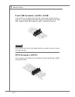
Front USB Connector: JUSB1 / JUSB2

This  connector,  compliant  with  Intel  I/O  Connectivity  Design  Guide,  is 

ideal for connecting high-speed USB interface peripherals such as USB 

HDD, digital cameras, MP3 players, printers, modems and the like. 

1.VC

C

3.US

B0-

10.N

C

5.US

B0+

7.Gro

und

9.No

Pin

8.Gro

und

6.US

B1+

4.US

B1-

2.VC

C

Important

Note that the pins of VCC and GND must be connected correctly to avoid 

possible damage.

GPIO Connector: JGPIO1

This connector is provided for the General-Purpose Input/Output (GPIO) 

peripheral module.

10.N

_GP

O3

8.N_

GPO

2

12.N

o Pin

6.N_

GPO

1

4.N_

GPO

0

2.5V

Outp

ut

1.3.3

V Ou

tput

3.N_

GPI0

5.N_

GPI1

7.N_

GPI2

9.N_

GPI3

11.G

ND

Summary of Contents for MS-9887

Page 1: ...IM QM67 MS 9887 v1 x Industrial Computer Board...

Page 2: ...ks of Microsoft Corporation AMI is registered trademark of Advanced Micro Devices Inc Award is a registered trademark of Phoenix Technologies Ltd Sound Blaster is registered trademark of Creative Tech...

Page 3: ...s on the equipment should be noted Never pour any liquid into the opening that could damage or cause electri cal shock If any of the following situations arises get the equipment checked by ser vice p...

Page 4: ...e interference by one or more of the measures listed below Reorient or relocate the receiving antenna Increase the separation between the equipment and receiver Connect the equipment into an outlet on...

Page 5: ...tger te nicht mehr als kommunale Abf lle entsorgt werden MSI hat europaweit verschiedene Sammel und Recyclingunternehmen beauftragt die in die Eu rop ische Union in Verkehr gebrachten Produkte am Ende...

Page 6: ...oducten die de merknaam MSI dragen en verkocht zijn in de EU Deze goederen kunnen geretourneerd worden op lokale inza melingspunten SRPSKI Da bi za titili prirodnu sredinu i kao preduze e koje vodi ra...

Page 7: ...sb rn ch MAGYAR Annak rdek ben hogy k rnyezet nket megv dj k illetve k rnyezetv d k nt fell pve az MSI eml kezteti nt hogy Az Eur pai Uni EU 2005 augusztus 13 n hat lyba l p az elektromos s elek troni...

Page 8: ...quency Interference Statement iv WEEE Waste Electrical and Electronic Equipment Statement v Chapter 1 Overview 1 1 Mainboard Specifications 1 2 Mainboard Layout 1 4 Chapter 2 Hardware Setup 2 1 Quick...

Page 9: ...67 accommo dates the Intel Core i7 i5 i3 or Celeron proces sor in rPGA 989 Socket G2 and supports 2 DDR3 1067 1333 DIMM slots to provide the maximum of 16GB memory capacity In the entry level and mid...

Page 10: ...D2 GR Codec Compliant with Azalia 1 0 specs Graphics Onboard graphics integrated in Intel HD Graphics Back Panel I O Connec tors Pin headers Back Panel I O 1 PS 2 mouse port 1 PS 2 keyboard port 1 VGA...

Page 11: ...t slot 1 Mini PCI Express x 1 slot 1 32 bit 33 66MHz 3 3v PCI slot Form Fac tor Mini ITX 17 0cm x 17 0cm Environ mental Operating Temperature 10o C to 60o C Storage Temperature 20o C to 80o C Humidity...

Page 12: ...t JAMP1 JUSB2 JFP1 J2 J_ME1 JDSW1 JCASE1 JGPIO1 JLVDS1 JSATA_PWR1 JSATA_PWR2 JUSB1 SATA3 SATA4 SATA1 SATA2 COM4 COM2 COM3 COM1 PCI1 DIMM1 DIMM2 JSPI1 SYSFAN1 CPUFAN1 Mini PCI Express Slot Codec Intel...

Page 13: ...1 5 MS 9887 CFast Slot CFast Slot...

Page 14: ...d hardware configurations Incorrect setting of jumpers and connectors may damage your main board Please pay special attention not to connect these headers in wrong direction DO NOT adjust any jumper w...

Page 15: ...2 10 Mini PCI Express Slot p 2 17 CPU p 2 3 J_ME1 p 2 14 JSPI1 p 2 14 Top LAN Jack Bottom USB 2 0 ports Top LAN Jack Bottom USB 2 0 ports T M B Line In Line Out Mic Top mouse Bottom keyboard Top VGA...

Page 16: ...heating will seriously damage the CPU and system Always make sure the cooling fan can work properly to protect the CPU from overheat ing Make sure that you apply an even layer of thermal paste or ther...

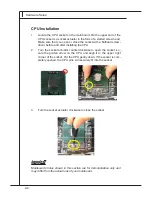
Page 17: ...lling the CPU Turn the socket actuator counterclockwise to open the socket Lo cate the golden arrow on the CPU and align it to the upper right corner of the socket Put the CPU gently down If the socke...

Page 18: ...MM gently forwards until the slot levers click and lock the DIMM in place Follow the same procedures to install the second DIMM if necessary To uninstall the DIMM flip the slot levers outwards and the...

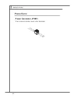
Page 19: ...2 6 Hardware Setup Power Connector JPWR1 This connector provides power to the mainboard 4 1 9 2 5 V 2 G r o u n d 3 1 9 2 5 V 1 G r o u n d Power Supply...

Page 20: ...igital audio on a single cable DVI D Port The DVI D Digital Visual Interface Digital connector allows you to con nect an LCD monitor It provides a high speed digital interconnection be tween the compu...

Page 21: ...ansmission OFF Green Lighting Transmission Yellow Blinking Green Lighting 1000M Cable Plug in No Transmission OFF Orange Lighting Transmission Yellow Blinking Orange Lighting In S3 S4 S5 Standby State...

Page 22: ...ecord this status and show a warning message on the screen To clear the warning you must enter the BIOS utility and clear the record 1 C I N T R U 2 G r o u n d Serial ATA Connector SATA1 SATA4 This c...

Page 23: ...a System Hard ware Monitor chipset on board you must use a specially designed fan with speed sensor to take advantage of the CPU fan control 1 G r o u n d 2 1 2 V 3 S e n s o r Important Please refer...

Page 24: ...2 6 L V D S 1 _ D A T A 3 P 2 4 L V D S 1 _ C K P 2 2 L V D S 1 _ D A T A 2 P 2 0 L V D S 1 _ D A T A 1 P 1 8 L V D S 1 _ D A T A 0 P 1 6 G N D 1 4 L V D S _ V D D E N 1 2 L D D C _ D A T A 1 0 L C D...

Page 25: ...1 0 N C 5 U S B 0 7 G r o u n d 9 N o P i n 8 G r o u n d 6 U S B 1 4 U S B 1 2 V C C Important Note that the pins of VCC and GND must be connected correctly to avoid possible damage GPIO Connector J...

Page 26: ...ignal Ground Data Set Ready Request To Send Clear To Send Power Source RS 232 RS 422 8 N C 3 T X 1 T X 6 N C 5 G N D 4 R X 7 N C 2 R X 9 N C PIN SIGNAL DESCRIPTION 1 2 3 4 5 6 7 8 9 422 TXD 422 RXD 42...

Page 27: ...2 14 Hardware Setup J_ME1 Connector J_ME1 This connector is provided for setting ME firmware update JSPI1 Connector JSPI1 This connector is provided for engineer debug only Enable Disable J_ME1 1 1 1...

Page 28: ...2 15 MS 9887 Jumper Audio Amplifier Connector JAMP1 The JAMP1 is used to connect audio amplifiers to enhance audio per formance 1 PIN SIGNAL 1 2 3 4 AMP_L AMP_L AMP_R AMP_R...

Page 29: ...e onboard serial ports Important Avoid adjusting the jumper when the system is on it will damage the mainboard LVDS Power Jumper JDSW1 Use this jumper to specify the LVDS power Important Avoid adjusti...

Page 30: ...nt Interconnect Slot The PCI slot supports LAN card SCSI card USB card and other add on cards that comply with PCI specifications Important When adding or removing expansion cards make sure that you u...

Page 31: ......

Reviews: