background image

Hardware Setup  

Industral Computer Board   

2-11

Hardware Setup  

Industral Computer Board   

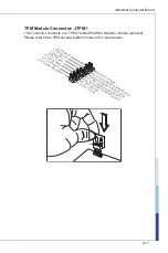
TPM Module Connector: JTPM1

Ths connector connects to a TPM (Trusted Platform Module) module (optonal). 

Please refer to the TPM securty platform manual for more detals. 

10.N

o Pin

14.G

roun

d

8.5V

Pow

er

12.G

roun

d

6.Se

rial IR

Q

4.3.3

V Po

wer

2.3V

Stan

dby p

ower

1.LP

C Clo

ck

3.LP

C Re

set

5.LP

C ad

dress

& dat

a pin

0

7.LP

C ad

dress

& dat

a pin

1

9.LP

C ad

dress

& dat

a pin

2

11.LP

C ad

dress

& dat

a pin

3

13.LP

C Fra

me

Summary of Contents for MS-98F5

Page 1: ...MS 98F5 v1 x Industrial Computer Board...

Page 2: ...tion Intel is a registered trademark of Intel Corporation Windows is a registered trademark of Microsoft Corporation AMI is a registered trademark of Advanced Micro Devices Inc Award is a registered t...

Page 3: ...Power Cord before inserting any add on card or mod ule All cautions and warnings on the equipment should be noted Never pour any liquid into the opening that could damage or cause electrical shock If...

Page 4: ...unsorted household waste Please use the public collection system to return recycle or treat them in compliance with the local regulations Taiwan For better environmental protection waste batteries sh...

Page 5: ...1 The changes or modifications not expressly approved by the party responsible for compliance could void the user s authority to operate the equipment Notice 2 Shielded interface cables and AC power...

Page 6: ...equency Interference Statement v WEEE Statement v 1 Overview 1 1 Mainboard Specifications 1 2 Mainboard Layout 1 4 2 Hardware Setup 2 1 Memory 2 3 Power Supply 2 4 Rear Panel I O 2 5 Connector 2 7 Jum...

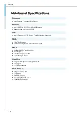
Page 7: ...accommodates the Intel Celeron Processor D M Series and supports up to 2 DDR3L 1333 MHz SO DIMM slots to provide the maximum of 8GB memory capacity In the entry level and mid range market segment MS 9...

Page 8: ...11G Gigabit Fast Ethernet controllers SATA 1 SATA 3Gb s port 1 mSATA slot shared with Mini PCIe slot Audio Realtek ALC887 audio codec 2 audio jacks 1 front audio pin header 1 amplifier pin header Grap...

Page 9: ...1 GPIO pin header 1 front panel pin header 1 front audio pin header 1 amplifier pin header 1 mouse keyboard connector 1 LVDS connector 1 chassis intrusion pin header 1 clear CMOS jumper 1 LVDS power j...

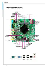
Page 10: ...T ATX Jumper SO DIMM Slot COM Port Connector USB 2 0 Pin Header Chassis Intrusion Pin Header SATA Port TPM Pin Header GPIO Pin Header Parallel Port Connector Back Panel CPU Fan Connector LVDS Connecto...

Page 11: ...lation be careful in holding the com ponents and follow the installation procedures For some components if you install in the wrong orientation the components will not work prop erly Use a grounded wr...

Page 12: ...SB1 JUSB2 2 10 Serial Port Connector COM2 COM6 2 10 TPM Module Connector JTPM1 2 11 Audio Amplifier Pinheader JAMP1 2 12 Front Audio Connector JAUD1 2 12 Chassis Intrusion Pin Header JCASE1 2 13 Keybo...

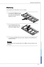
Page 13: ...on the DIMM with the key on the slot and insert the DIMM into the slot 2 Push the DIMM gently down wards until the slot levers click and lock the DIMM in place 3 To uninstall the DIMM flip the slot l...

Page 14: ...ake sure the plug of the power supply is inserted in the proper orientation and the pins are aligned Then push down the plug firmly into the connector SATA Power Connector JPW1 This connector is used...

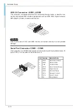
Page 15: ...other serial devices directly to the connector PIN SIGNAL DESCRIPTION 1 2 3 4 5 6 7 8 9 DCD RXD TXD DTR GND DSR RTS CTS VCC_COM1 Data Carrier Detect Receive Data Transmit Data Data Terminal Ready Sign...

Page 16: ...stablished On blinking The computer is communicating with another computer on the LAN Right Green Off 10 Mbit sec data rate is selected On 100 Mbit sec data rate is selected Orange On 1000 Mbit sec da...

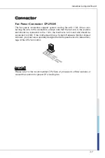
Page 17: ...the red wire is the positive and should be connected to the 12V the black wire is Ground and should be connected to GND If the motherboard has a System Hardware Monitor chipset onboard you must use a...

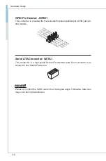
Page 18: ...Purpose Input Output GPIO periph eral module Serial ATA Connector SATA1 This connector is a high speed Serial ATA interface port Each connector can connect to one Serial ATA device Important Please d...

Page 19: ...S B _ D A T A 1 2 3 G N D 2 1 L V D S A _ D A T A 3 1 9 L V D S A _ D A T A 3 1 7 G N D 1 5 L V D S A _ D A T A 1 1 3 L V D S A _ D A T A 1 1 1 L V D S _ B L O N 9 L _ B K L T _ C T R L 7 L V D S _ D...

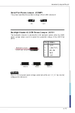
Page 20: ...B 1 2 V C C Important Note that the pins of VCC and GND must be connected correctly to avoid possible damage Serial Port Connector COM2 COM6 This connector is a 16550A high speed communications port...

Page 21: ...security platform manual for more details 1 0 N o P i n 1 4 G r o u n d 8 5 V P o w e r 1 2 G r o u n d 6 S e r i a l I R Q 4 3 3 V P o w e r 2 3 V S t a n d b y p o w e r 1 L P C C l o c k 3 L P C R...

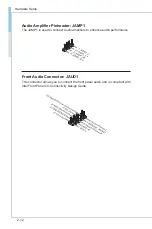
Page 22: ...r Pinheader JAMP1 The JAMP1 is used to connect audio amplifiers to enhance audio performance Front Audio Connector JAUD1 This connector allows you to connect the front panel audio and is compliant wit...

Page 23: ...connector is provided to connect a keyboard and a mouse Parallel Port Connector JLPT1 The mainboard provides a 26 pin header for connection to an optional parallel port bracket The parallel port is a...

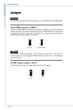
Page 24: ...ation With the CMOS RAM the system can automatically boot OS every time it is turned on If you want to clear the system configuration set the jumper to clear data 1 1 Normal Clear CMOS Important You c...

Page 25: ...he backlight connector is provided for LCD backlight options while the LVDS power jumper allows users to select the operation voltage of the LVDS flat panel 1 2 9 10 VCC5 1 2 9 10 VCC3 1 2 9 10 VCC3 P...

Page 26: ...ess Slot The Mini PCIe slot is provided for wireless LAN card TV tuner card Robson NAND Flash card and mSATA devices Important When adding or removing expansion cards make sure that you unplug the pow...

Page 27: ...essage appears on the screen at system startup and re quests users to run SETUP Users want to change the default settings for customized features Important Please note that BIOS update assumes technic...

Page 28: ...ars before you respond and you still wish to enter Setup restart the system by turning it OFF and On or pressing the RESET button You may also restart the system by simultaneously pressing Ctrl Alt an...

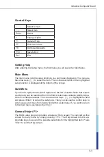
Page 29: ...ub Menu If you find a right pointer symbol appears to the left of certain fields that means a sub menu can be launched from this field A sub menu contains additional op tions for a field parameter You...

Page 30: ...u to specify the priority of boot devices Security Use this menu to set supervisor and user passwords Chipset This menu controls the advanced features of the onboard chipsets Power Use this menu to sp...

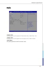
Page 31: ...ain System Date This setting allows you to set the system date The date format is Day Month Date Year System Time This setting allows you to set the system time The time format is Hour Minute Second S...

Page 32: ...screen logo during the boot up sequence hiding normal POST messages When it is disabled the BIOS will display the normal POST messages instead of the full screen logo Please note that enabling this BI...

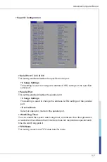
Page 33: ...llel Port This setting enables disables the parallel port Change Settings This setting is used to change the address IRQ settings of the parallel port Device Mode Select an operation mode for the para...

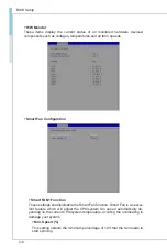
Page 34: ...Fan Configuration Smart FAN1 Function These settings enable disable the Smart Fan function Smart Fan is an excel lent feature which will adjust the CPU system fan speed automatically de pending on th...

Page 35: ...rt code in the buffer the processor disables code execu tion preventing damage or worm propagation Intel Virtualization Technology Virtualization enhanced by Intel Virtualization Technology will allow...

Page 36: ...EHCI controller The Enhanced Host Controller Interface EHCI specification describes the register level interface for a Host Controller for the Universal Serial Bus USB Revision 2 0 Legacy USB Support...

Page 37: ...Industrial Computer Board 3 11 Industrial Computer Board GPIO Group Configuration GPO0 GPO3 These settings control the operation mode of the specified GPIO...

Page 38: ...o boot in UEFI mode disable CSM Support to speed up the boot process Boot Option Priorities This setting allows users to set the sequence of boot devices where BIOS at tempts to load the disk operatin...

Page 39: ...sword controls access to the BIOS Setup utility User Password User Password controls access to the system at boot and to the BIOS Setup utility Chassis Intrusion The field enables or disables the feat...

Page 40: ...rd attached This setting enables disables the operation of console re direction When set to Enabled BIOS redirects and sends all contents that should be displayed on the screen to the serial COM port...

Page 41: ...data from one device to another to ensure that the receiving device can handle all of the incoming data This is particularly important where the sending device is ca pable of sending data much faster...

Page 42: ...e will not be available Security Configuration Intel R TXE Configuration Intel Trusted Execution Technology provides highly scalable platform security in physical and virtual infrastructures Intel R A...

Page 43: ...m memory made available at boot time by the system BIOS for video Pre allocated memory is also known as locked memory This is because it is locked for video use only and as such is invisible and unabl...

Page 44: ...Last State Restores the system to the previous status before power failure or interrupt occurred Deep S5 The setting enables disables the Deep S5 power saving mode S5 is almost the same as G3 Mechanic...

Page 45: ...m will be awakened from power saving modes when activity or input signal of onboard PCIE PME is detected USB from S3 S4 The item allows the activity of the USB device to wake up the system from S3 S4...

Page 46: ...Defaults Use this menu to load the default values set by the motherboard manufacturer specifically for optimal performance of the motherboard Save as User Defaults Save changes as the user s default...

Page 47: ...2 A 1 This appendix provides the sample codes of WDT Watch Dog Timer and GPIO General Purpose Input Output Appendix WDT GPIO...

Page 48: ...Change to WDT mov dx SIO_INDEX_Port mov al 07h out dx al mov dx SIO_DATA_Port mov al WatchDog_LDN out dx al Acive WDT mov dx SIO_INDEX_Port mov al 30h out dx al mov dx SIO_DATA_Port in al dx or al 01...

Page 49: ...mputer Board GPIO A GPIO control tool is provided in the driver CD GPI0 GPI3 display GPI0 to GPI3 status GPO0 GPO3 display GPO0 to GPO3 status and setting output high or low Apply Setting Settings wil...

Page 50: ......

Reviews: