background image

2-3

MS-98H7

Connector

Fan Power Connector: CPUFAN1

The fan power connectors support system cooling fan with +12V. When connecting 

the wire to the connectors, always note that the red wire is the positive and should 

be connected to the +12V; the black wire is Ground and should be connected to 

GND. If the motherboard has a System Hardware Monitor chipset onboard, you 

must use a specially designed fan with speed sensor to take advantage of the 

CPU fan control.

Important

Please  refer  to  the  recommended  CPU  fans  at  processor’s  official  website  or 

consult the vendors for proper CPU cooling fan.

Summary of Contents for MS-98H7

Page 1: ...i MS 98H7 COM Express Type 6 Basic Module...

Page 2: ...e right to make changes without notice Trademarks All trademarks are the properties of their respective owners Revision History Revision Date V1 0 2018 11 Technical Support If a problem arises with yo...

Page 3: ...e anything over the power cord Always Unplug the Power Cord before inserting any add on card or module All cautions and warnings on the equipment should be noted Never pour any liquid into the opening...

Page 4: ...orted household waste Please use the public collection system to return recycle or treat them in compliance with the local regulations Taiwan For better environmental protection waste batteries should...

Page 5: ...ch can be determined by turning the equipment off and on the user is encouraged to try to correct the interference by one or more of the following measures Reorient or relocate the receiving antenna I...

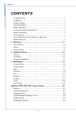
Page 6: ...ent v 1 Overview 1 1 Specifications 1 2 Layout 1 4 Block Diagram 1 5 2 Hardware Setup 2 1 Memory 2 2 Connector 2 3 Hardware Installation 2 7 3 BIOS Setup 3 1 Entering Setup 3 2 The Menu Bar 3 4 Main 3...

Page 7: ...le Express Type 6 Basic Module Integrating core CPU and memory functionality it is the entry level model for applications looking to transition from other small form factor solutions to COM Express an...

Page 8: ...LM GbE PHY LAN iAMT 12 x supported Graphics Graphics integrated in Intel processor 1 LVDS 18 24 Bit Dual Channel LVDS resolution up to 1920x1200 60 Hz 3 DDI ports support HDMI1 4 or DP1 2 multiplexed...

Page 9: ...3 1 to carrier board 8 USB 2 0 to carrier board PCI Express Interface PEG 1 PCIe x16 supports 1 x16 or 2 x8 or 1 x8 or 2 x4 PCIe supports up to 5 devices and 8 lanes 5 PCIe x1 or 4 PCIe x1 1 PCIe x4 o...

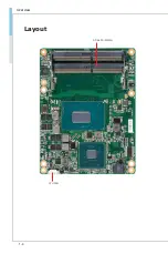
Page 10: ...1 4 Overview Layout CPU FAN DDR4 SO DIMMs...

Page 11: ...1 5 MS 98H7 Block Diagram...

Page 12: ......

Page 13: ...lation be careful in holding the com ponents and follow the installation procedures For some components if you install in the wrong orientation the components will not work prop erly Use a grounded wr...

Page 14: ...the key on the slot and insert the DIMM into the slot 2 Push the DIMM gently downwards until the slot levers click and lock the DIMM in place 3 To uninstall the DIMM flip the slot levers outwards and...

Page 15: ...sitive and should be connected to the 12V the black wire is Ground and should be connected to GND If the motherboard has a System Hardware Monitor chipset onboard you must use a specially designed fan...

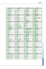
Page 16: ...nectors are used to interface the COM Express module board to a carrier board Connect the COM Express connectors located on the solder side of the module board as indicated below to the COM Express co...

Page 17: ...3 A38 USB_6_7_OC B38 USB_4_5_OC C38 DDI3_DDC_AUX_SEL D38 RSVD A39 USB4 B39 USB5 C39 DDI3_PAIR0 D39 DDI2_PAIR0 A40 USB4 B40 USB5 C40 DDI3_PAIR0 D40 DDI2_PAIR0 A41 GND FIXED B41 GND FIXED C41 GND FIXED...

Page 18: ...3 GPO0 B93 VGA_HSYNC C93 GND D93 GND A94 SPI_CLK B94 VGA_VSYNC C94 PEG_RX13 D94 PEG_TX13 A95 SPI_MOSI B95 VGA_I2C_CK C95 PEG_RX13 D95 PEG_TX13 A96 TPM_PP B96 VGA_I2C_DAT C96 GND D96 GND A97 TYPE10 B97...

Page 19: ...rovided to guide users on how to install the module board onto the carrier board of their choice and should be held for reference only 1 Remove the protection cover of COM Express connectors on the mo...

Page 20: ...2 8 Hardware Setup 3 Locate the threaded standoffs on the carrier board 4 Install the module board to the carrier board via the COM Express connectors Press the module board down firmly...

Page 21: ...over and remove the protective film from its thermal paste Mount the heat spreader onto the module board with mounting holes aligned 6 Use the provided mounting screws to secure the heat spreader to t...

Page 22: ......

Page 23: ...essage appears on the screen at system startup and re quests users to run SETUP Users want to change the default settings for customized features Important Please note that BIOS update assumes technic...

Page 24: ...ou respond and you still wish to enter Setup restart the system by turning it OFF and On or pressing the RESET button You may also restart the system by simultaneously pressing Ctrl Alt and De lete ke...

Page 25: ...right pointer symbol appears to the left of certain fields that means a sub menu can be launched from this field A sub menu contains additional op tions for a field parameter You can use arrow keys t...

Page 26: ...pecify the priority of boot devices Security Use this menu to set supervisor and user passwords Chipset This menu controls the advanced features of the onboard chipsets Power Use this menu to specify...

Page 27: ...g allows you to set the system date The date format is Day Month Date Year System Time This setting allows you to set the system time The time format is Hour Minute Second SATA Mode Selection This set...

Page 28: ...the booting sequence This delay ensures that the logo is displayed for a suf ficient amount of time Therefore it is recommended that you disable this BIOS feature for a faster boot up time Bootup NumL...

Page 29: ...s simultaneously In this way the system performance is highly improved If you disable the function the processor will use only one core to execute the instructions Please disable this item if your ope...

Page 30: ...ables the parallel port Change Settings This setting is used to change the address IRQ settings of the parallel port Device Mode Select an operation mode for the parallel port FIFO Mode This setting c...

Page 31: ...of the specified serial port Watch Dog Timer You can enable the system watch dog timer a hardware timer that generates a reset when the software that it monitors does not respond as expected each tim...

Page 32: ...ting to damage your system PCI PCIE Device Configuration Legacy USB Support Set to Enabled if you need to use any USB 1 1 2 0 device in the operating system that does not support or have any USB 1 1 2...

Page 33: ...3 11 MS 98H7 GPIO Group Configuration the Carrier Board JGPIO1 2 GPO0 GPO3 These settings control the operation mode of the specified GPIO...

Page 34: ...of primary video for your system Boot Option Priorities This setting allows users to set the sequence of boot devices where BIOS at tempts to load the disk operating system Hard Drive BBS Priorities...

Page 35: ...ssword controls access to the system at boot and to the BIOS Setup utility Intel BIOS Guard Support Intel BIOS Guard Support ensures that updates to system BIOS flash are secure Intel Trusted Executio...

Page 36: ...FW Configuration Firmware Update Configuration ME FW Image Re Flash This setting enables disables the ME FW image reflash PTT Configuration Intel Platform Trust Technology PTT is a platform functiona...

Page 37: ...E Debug Configuration This menu provides settings for ME Debug Configuration AMT Configuration Intel Active Management Technology AMT is hardware based technology for remotely managing and securing PC...

Page 38: ...tings enable disable the SHA 1 PCR Bank and SHA256 PCR Bank Pending Operation This setting shows pending operation Platform Hierarchy Storage Hierarchy Endorsement Hierarchy These settings enable disa...

Page 39: ...terminal screen Besides all data received from the serial port is interpreted as keystrokes from a local keyboard Console Redirection Settings COM1 Terminal Type To operate the system s console redir...

Page 40: ...for ANSI VT100 terminals Recorder Mode Resolution 100x31 These settings enable disable the recorder mode and the resolution 100x31 Putty Keypad PuTTY is a terminal emulator for Windows This setting co...

Page 41: ...of band management The next best choice is VT100 and then VT100 Bits per second This setting selects serial port transmission speed The speed must be matched on the other side Long or noisy lines may...

Page 42: ...cked memory This is because it is locked for video use only and as such is invisible and unable to be used by the operating system DVMT Total Gfx Mem This setting specifies the memory size for DVMT Pr...

Page 43: ...The setting enables disables the Deep S5 power saving mode S5 is almost the same as G3 Mechanical Off except that the PSU still supplies power at a mini mum to the power button to allow return to S0 A...

Page 44: ...will be awakened from power saving modes when input signals on the serial Ring Indicator RI line or input signals of onboard PCIE PME are detected RTC When Enabled your can set the date and time at wh...

Page 45: ...ed Defaults Use this menu to load the default values set by the motherboard manufacturer specifically for optimal performance of the motherboard Save as User Defaults Save changes as the user s defaul...

Page 46: ......

Page 47: ...A 1 MS 98H7 This appendix provides WDT Watch Dog Timer GPIO General Purpose Input Output and LVDS Backlight programming guide Appendix GPIO WDT BKL Programming...

Page 48: ...A 2 GPIO WDT BKL Programming CONTENT Abstract A 3 General Purposed IO A 4 Watchdog Timer A 5 LVDS Backlight Brightness Control A 6 SMBus Access A 7 Embedded Controller A 8...

Page 49: ...ded for customer interest Inportb Outportb Inportl and Outportl are basic functions used for access IO ports and defined as following Inportb Read a single 8 bit I O port Outportb Write a single byte...

Page 50: ...et the value of GPO address 3 Write the value back to the OFFSET in EC RAM of GPO Example Set N_GPO0 output high val EC_ReadByte 0x97 Read value from N_GPO0 val val 1 4 Set N_GPO0 address bit 4 to 1 o...

Page 51: ...DT will reset the system Associated access method EC_ReadByte and EC_WriteByte are provided in part 5 2 1 Set WDT Time and Enable WDT EC_WriteByte 0x98 Time Enable WDT immediately after setting WDT ti...

Page 52: ...ht 1 Write 0xED into address 0x7F on SMBus device 0x42 2 Write desired backlight level from 0x0 30 to 0x10 100 into address 0x6E on SMBus device 0x42 Example Set LVDS backlight level to 0x10 100 SMBus...

Page 53: ...om SMBus device DEVID Outportb LOWORD SMBUS_BASE 0xFE Outportb LOWORD SMBUS_BASE 0x04 DEVID 1 out Base 04 DEVID 1 Outportb LOWORD SMBUS_BASE 0x03 OFFSET out Base 03 OFFSET Outportb LOWORD SMBUS_BASE 0...

Page 54: ...k 5 2 EC_ReadByte char OFFSET Read the value from OFFSET of EC RAM WaitPortStatus EC_STAT_IBF false Wait IBF 0 Outportb EC_CMD_PORT 0x80 0x80 EC read command WaitPortStatus EC_STAT_IBF false Wait IBF...

Reviews: