background image

A-3

WDT & GPIO

MS-98I8   

GPIO Sample Code


GPI 0 ~ GPI 3 


GPI 0  GPI 1  GPI 2  GPI 3   


IO Address 


SIO GPIO Register  8Ah 

8Ah 

8Ah 

8Ah 


Bit 


Sample code 

#1 


GPO 0 ~ GPO 3 


GPO 0  GPO 1  GPO 2  GPO 3   


IO Address 


SIO GPIO Register  89h 

89h 

89h 

89h 


Bit 


Sample code 

#2 


SIO_INDEX_Port  


equ  

04Eh  

SIO_DATA_Port   


equ  

04Fh  

SIO_UnLock_Value   

equ  

087h  

SIO_Lock_Value  


equ  

0AAh  

SIO_LDN_GPIO   


equ  

06h  

SIO_GPIO_Data   


equ  

089h 

SIO_GPIO_Status 


equ  

08Ah 

GPI_0   


equ  

00000001b  

GPO_0   


equ  

00010000b  


Sample Code: 


#1 : Get GPI 0 status  

; Enable config mode  

mov  

dx, SIO_INDEX_Port  

mov  

al, SIO_UnLock_Value  

out  

dx, al  

jmp  

short $+2   


;Io_delay  

jmp  

short $+2   


;Io_delay  

out  

dx, al  

; Switch GPIO Configuration for SIO LDN 0x06  

mov  

dx, SIO_INDEX_Port  

mov  

al, 07h  

out  

dx, al  

mov  

dx, SIO_DATA_Port  

mov  

al, SIO_LDN_GPIO  

out  

dx, al  

; Get GPI 0 Pin Status Register  

Summary of Contents for MS-98I8

Page 1: ...i MS 98I8 v1 x Industrial Computer Board...

Page 2: ...hout notice Trademarks All trademarks are the properties of their respective owners Revision History Revision Date V1 1 2016 12 Technical Support If a problem arises with your system and no solution c...

Page 3: ...e anything over the power cord Always Unplug the Power Cord before inserting any add on card or mod ule All cautions and warnings on the equipment should be noted Never pour any liquid into the openin...

Page 4: ...orted household waste Please use the public collection system to return recycle or treat them in compliance with the local regulations Taiwan For better environmental protection waste batteries should...

Page 5: ...ifications not expressly approved by the party responsible for compliance could void the user s authority to operate the equipment Notice 2 Shielded interface cables and AC power cord if any must be u...

Page 6: ...ment and Handling Rule 2011 and prohibits use of lead mercury hexavalent chromium polybrominated biphenyls or polybrominated diphenyl ethers in concentrations exceeding 0 1 weight and 0 01 weight for...

Page 7: ...rarily regulating the permitted limits for a number of hazardous substances in electronic and electric products Vi t Nam RoHS K t ng y 01 12 2012 t t c c c s n ph m do c ng ty MSI s n xu t tu n th Th...

Page 8: ...Interference Statement v WEEE Statement v 1 Overview 1 1 Motherboard Specifications 1 2 Motherboard Layout 1 4 2 Hardware Setup 2 1 Memory 2 3 Power Supply 2 4 Rear Panel I O 2 5 Connector 2 6 Jumper...

Page 9: ...efficiency the MS 98I8 supports up to 8GB of onboard DDR3L 1600MHz memory and allows connection to 3 or 2 independent displays with HDMI DisplayPort and LVDS outputs The MS 98I8 is durable under extre...

Page 10: ...TL8111G GbE LAN Storage 1 x SATA 6Gb s port 1 x mSATA 6Gb s slot shared with MINI_PCIE1 Audio Realtek ALC887 VD2 CG HD Audio Codec 1 x Front audio connector 1 x Amplifier connector Graphics HD Graphic...

Page 11: ...io connector 1 x Amplifier connector 1 x GPIO connector 1 x LVDS connector 1 x Inverter connector 1 x PS 2 keyboard mouse connector 1 x LPC connector 1 x Clear CMOS jumper 1 x Inverter power jumper 1...

Page 12: ...r COM Port Power Jumper DC Power Connector SATA Power Connector Mini PCIe Slot Back Panel LVDS Power Jumper Inverter Connector Inverter Power Jumper LVDS Connector Front Panel Connector Front Audio Co...

Page 13: ...llation be careful in holding the components and follow the installation procedures For some components if you install in the wrong orientation the components will not work properly Use a grounded wri...

Page 14: ...ctor JGPIO1 2 8 RS232 Serial Port Connector JCOM2 JCOM3 JCOM4 2 8 RS232 422 485 Serial Port Connector JCOM1 2 9 LVDS Inverter Connector JINVDD1 2 10 LVDS Connector JLVDS1 2 10 Keyboard Mouse Connector...

Page 15: ...key on the slot and insert the DIMM into the slot 2 Push the DIMM gently downwards until the slot levers click and lock the DIMM in place 3 To uninstall the DIMM flip the slot levers outwards and the...

Page 16: ...ed to provide power to the motherboard SATA Power Connector JPW1 This connector is used to provide power to SATA devices 2 G N D 3 G N D 1 V C C 5 4 1 2 V Important Make sure that all power connectors...

Page 17: ...s a digital display interface standard This connector is used to connect a monitor with DisplayPort inputs h h RJ45 GbE LAN Port The standard single RJ45 LAN jack is provided for connection to the Loc...

Page 18: ...is Ground and should be connected to GND If the motherboard has a System Hardware Monitor chipset onboard you must use a specially designed fan with speed sensor to take advantage of the CPU fan cont...

Page 19: ...and is compliant with Intel Front Panel I O Connectivity Design Guide Front Audio Connector JAUD1 This connector allows you to connect the front panel audio and is compliant with Intel Front Panel I O...

Page 20: ...nnector is a 16550A high speed communications port that sends receives 16 bytes FIFOs You can attach serial devices to it through the optional serial port bracket PIN SIGNAL DESCRIPTION 1 2 3 4 5 6 7...

Page 21: ...y Signal Ground Data Set Ready Request To Send Clear To Send 5V or 12V selected by jumper RS422 PIN SIGNAL DESCRIPTION 1 2 3 4 5 6 7 8 9 422 TXD 422 TXD 422 RXD 422 RXD GND NC NC NC NC Transmit Data N...

Page 22: ...nnector provides a digital interface typically used with flat panels After connecting an LVDS interface flat panel to the JLVDS1 be sure to check the panel datasheet and set the LVDS jumper to proper...

Page 23: ...ras MP3 players printers modems and the like Important Note that the pins of VCC and GND must be connected correctly to avoid pos sible damage LPC Debug Port Connector JLPC1 With TPM Support This conn...

Page 24: ...ith the CMOS RAM the system can automatically boot OS every time it is turned on If you want to clear the system configuration set the jumper to clear data 1 1 Normal Clear CMOS Important You can clea...

Page 25: ...eration voltage of the specified serial port 1 1 5V 12V LVDS Power Jumper JVDD1 Use this jumper to specify the operation voltage of the LVDS display 1 1 3V 5V LVDS Inverter Power Jumper JINV1 Use this...

Page 26: ...CIe cards MINI_PCIE1 supports Mini PCIe and mSATA cards MINI_PCIE2 only supports Mini PCIe cards Important When adding or removing expansion cards make sure that you unplug the power supply first Mean...

Page 27: ...message appears on the screen at system startup and requests users to run SETUP Users want to change the default settings for customized features Important Please note that BIOS update assumes technic...

Page 28: ...efore you respond and you still wish to enter Setup restart the system by turning it OFF and On or pressing the RESET button You may also restart the system by simultaneously pressing Ctrl Alt and Del...

Page 29: ...right pointer symbol appears to the left of certain fields that means a sub menu can be launched from this field A sub menu contains additional options for a field parameter You can use arrow keys to...

Page 30: ...pecify the priority of boot devices Security Use this menu to set supervisor and user passwords Chipset This menu controls the advanced features of the onboard chipsets Power Use this menu to specify...

Page 31: ...g allows you to set the system date The date format is Day Month Date Year System Time This setting allows you to set the system time The time format is Hour Minute Second SATA Mode Selection This set...

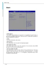
Page 32: ...the booting sequence This delay ensures that the logo is displayed for a sufficient amount of time Therefore it is recommended that you disable this BIOS feature for a faster boot up time Bootup NumL...

Page 33: ...ct Select an operation mode for the specified serial port FIFO Mode This setting controls the FIFO data transfer mode Shared IRQ Mode This setting provides the system with the ability to share interru...

Page 34: ...tages temperatures and all fans speeds Smart Fan Configuration Smart SYSFAN Target This setting enables disables the Smart Fan function Smart Fan is an excellent feature which will adjust the CPU syst...

Page 35: ...titions With virtualization one computer system can function as multiple Virtual systems EIST EIST Enhanced Intel SpeedStepTechnology allows the system to dynamically adjust processor voltage and core...

Page 36: ...stem that does not support or have any USB 1 1 2 0 driver installed such as DOS and SCO Unix Audio Controller This setting enables disables the onboard audio controller Launch OnBoard LAN OpROM These...

Page 37: ...3 11 MS 98I8 GPIO Group Configuration GPO0 GPO3 These settings control the operation mode of the specified GPIO...

Page 38: ...ction This setting allows users to select the Operating System Boot Option Priorities This setting allows users to set the sequence of boot devices where BIOS attempts to load the disk operating syste...

Page 39: ...3 MS 98I8 Security Administrator Password Administrator Password controls access to the BIOS Setup utility User Password User Password controls access to the system at boot and to the BIOS Setup utili...

Page 40: ...e When set to Disable the OS will not show security device TCG EFI protocol and INT1A interface will not be available Serial Port Console Redirection Console Redirection Console Redirection operates i...

Page 41: ...irection Bits per second Data Bits Parity Stop Bits This setting specifies the transfer rate bits per second data bits parity stop bits of Console Redirection Flow Control Flow control is the process...

Page 42: ...or not to keep terminals console redirection running after the BIOS POST has booted Security Configuration TXE FW Version The setting shows the firmware information of the Intel Trusted Execution Engi...

Page 43: ...Gfx Mem This setting specifies the memory size for DVMT LCD Panel Type This setting specifies the LCD panel type LVDS Backlight Control This setting controls the intensity of the LVDS backlight PlayR...

Page 44: ...Sleep Mode The setting enables disables the Deep S5 power saving mode S5 is almost the same as G3 Mechanical Off except that the PSU still supplies power at a minimum to the power button to allow ret...

Page 45: ...S3 S4 The item allows the activity of the USB device to wake up the system from S3 S4 sleep state RTC When Enabled your can set the date and time at which the RTC real time clock alarm awakens the sys...

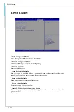
Page 46: ...ized Defaults Use this menu to load the default values set by the motherboard manufacturer specifically for optimal performance of the motherboard Save as User Defaults Save changes as the user s defa...

Page 47: ...2 A 1 This appendix provides the sample codes of WDT Watch Dog Timer and GPIO General Purpose Input Output Appendix WDT GPIO...

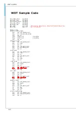
Page 48: ...nge to WDT mov dx SIO_INDEX_Port mov al 07h out dx al mov dx SIO_DATA_Port mov al WatchDog_LDN out dx al Acive WDT mov dx SIO_INDEX_Port mov al 30h out dx al mov dx SIO_DATA_Port in al dx or al 01h ou...

Page 49: ...Fh SIO_UnLock_Value equ 087h SIO_Lock_Value equ 0AAh SIO_LDN_GPIO equ 06h SIO_GPIO_Data equ 089h SIO_GPIO_Status equ 08Ah GPI_0 equ 00000001b GPO_0 equ 00010000b Sample Code 1 Get GPI 0 status Enable...

Page 50: ...EX_Port mov al SIO_UnLock_Value out dx al jmp short 2 Io_delay jmp short 2 Io_delay out dx al Switch GPIO Configuration for SIO LDN 0x06 mov dx SIO_INDEX_Port mov al 07h out dx al mov dx SIO_DATA_Port...

Reviews: