background image

Hardware Setup

MS-7667

Chapter 2 

2-7

Hardware Setup

MS-7667

Chapter 2 

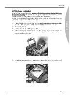
Important

Read the CPU status in BIOS.
Whenever CPU is not installed, always protect your CPU socket pin with the plastic 

cap covered to avoid damaging.
Mainboard photos shown in this section are for demonstration of the CPU/ cooler in-

stallation only. The appearance of your mainboard may vary depending on the model 

you purchase.
Please refer to the documentation in the CPU fan package for more details about the 

CPU fan installation.


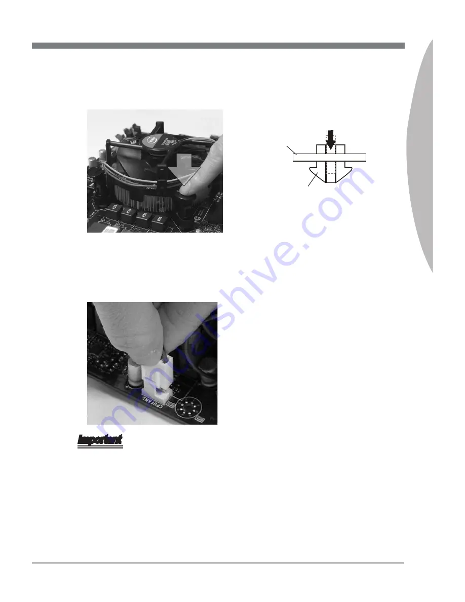
Press the four hooks down to fasten 

the cooler.

10.

Turn over the mainboard to confirm 

that  the  clip-ends  are  correctly  in-

serted.

11.

Finally, attach the CPU Fan cable to 

the CPU fan connector on the main-

board.

12.

Mainboard

Hook

Summary of Contents for MS7667

Page 1: ...ATX mainboard The series mainboards are based on Intel P67 chipsets for optimal system efficiency Designed to fit the advanced Intel LGA1155 processor the series deliver a high performance and profess...

Page 2: ...L8111E IEEE 1394 1 IEEE 1394 rear port by VIA VT6315N Audio Chip integrated by Realtek ALC892 Flexible 8 channel audio with jack sensing Compliant with Azalia 1 0 Spec SATA 4 SATA 3Gb s ports SATA3 6...

Page 3: ...IEEE 1394 port 6 USB 2 0 ports 1 eSATA port 1 LAN port 6 flexible audio ports On Board 2 USB 2 0 connector 2 USB 3 0 ports 1 Front Panel Audio connector 1 OC switch LED connector Slots 2 PCIE 2 0 x16...

Page 4: ...R_CMOS SLOT1 DIMM1 DIMM3 DIMM2 DIMM4 SLOT2 SLOT3 SLOT4 ESATA FRONT_AUDIO BATT LOCK Top LAN Jack Bottom USB2 0 ports T M B Line Out Line In Mic T CS Out M RS Out B SS Out Top USB 2 0 ports Bottom eSATA...

Page 5: ...be careful in holding the components and follow ing the installation procedures For some components if you install in the wrong orientation the components will not work properly Use a grounded wrist...

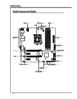
Page 6: ...uide Back Panel p 2 11 CPU p 2 4 CPUFAN p 2 14 DDR3 p 2 8 PWR2 p 2 10 PWR1 p 2 10 CLEAR_CMOS p 2 17 SATA1 6 p 2 13 JFP3 p 2 16 FRONT_PANEL p 2 14 USB3_1 2 p 2 15 FRONT_AUDIO p 2 16 PCIE p 2 18 SYSFAN1...

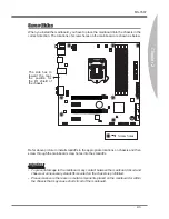
Page 7: ...e locations on chassis and then screw through the mainboard screw holes into the standoffs Important To prevent damage to the mainboard any contact between the mainboard circuit and chassis or unneces...

Page 8: ...PU and the heatsink to enhance heat dissipation Replacing the CPU While replacing the CPU always turn off the ATX power supply or unplug the power supply s power cord from the grounded outlet first to...

Page 9: ...mage of your CPU mainboard The CPU socket has a plastic cap on it to protect the contact from damage Before you install CPU always cover it to protect the socket pin Romove the cap Open the load level...

Page 10: ...ab 7 Make sure the four hooks are in por per position before you install the cooler 8 Align the holes on the mainboard with the heatsink Push down the cooler until its four clips get wedged into the h...

Page 11: ...on of the CPU cooler in stallation only The appearance of your mainboard may vary depending on the model you purchase Please refer to the documentation in the CPU fan package for more details about th...

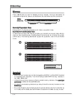
Page 12: ...system performance The following illustrations explain the population rules for Dual Channel mode 1 DIMM1 DIMM3 DIMM2 DIMM4 2 DIMM1 DIMM3 DIMM2 DIMM4 Important DDR3 memory modules are not interchangea...

Page 13: ...h it in until the golden finger on the memory module is deeply inserted in the DIMM slot The plastic clip at each side of the DIMM slot will automatically close when the memory module is properly seat...

Page 14: ...pply please plug your power supply along with pin 1 pin 13 1 3 3 3 V 1 3 3 V 1 4 1 2 V 2 3 3 V 1 5 G r o u n d 3 G r o u n d 1 6 P S O N 4 5 V 1 7 G r o u n d 5 G r o u n d 1 8 G r o u n d 6 5 V 1 9 G...

Page 15: ...sion to external speakers through an optical fiber cable IEEE 1394 Port The IEEE 1394 port on the back panel provides connection to IEEE 1394 devices eSATA Port The eSATA External SATA port is for att...

Page 16: ...Mbit sec data rate is selected Orange On 1000 Mbit sec data rate is selected Audio Ports These audio connectors are used for audio devices It is easy to differentiate between audio effects according t...

Page 17: ...erface port Each connector can connect to one Serial ATA device The MB layout in this figure is for reference only SATA1 2 6Gb s SATA3 6 3Gb s SATA3_4 SATA1_2 SATA5_6 ESATA supported by JMB362 support...

Page 18: ...of the CPU fan control 1 G r o u n d 2 1 2 V 3 S e n s o r 4 C o n t r o l 1 G r o u n d 2 1 2 V 3 S e n s o r CPU_FAN SYSFAN1 2 Important Please refer to the recommended CPU fans at processor s offi...

Page 19: ...9 N o P i n 8 G r o u n d 6 U S B 1 4 U S B 1 2 V C C The MB layout in this figure is for reference only USB Bracket optional Important Note that the pins of VCC and GND must be connected correctly to...

Page 20: ...de 1 M I C L 3 M I C R 1 0 H e a d P h o n e D e t e c t i o n 5 H e a d P h o n e R 7 S E N S E _ S E N D 9 H e a d P h o n e L 8 N o P i n 6 M I C D e t e c t i o n 4 N C 2 G r o u n d OC switch LED...

Page 21: ...e the system is off Then return to 1 2 pin position Avoid clearing the CMOS while the system is on it will damage the mainboard CLEAR_CMOS Keep Data Clear Data 1 1 1 Clear BIOS Password Jumper PASSSWO...

Page 22: ...2 18 Hardware Setup Slots PCIE Peripheral Component Interconnect Express Slot The PCIE slot supports the PCIE interface expansion card PCIE x16 Slot PCIE x1 Slot...

Reviews: