2-12
Hardware Setup
▍
MS-7511
Hardware Setup
▍
MS-7511
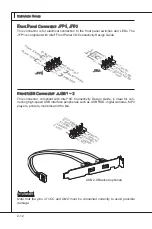
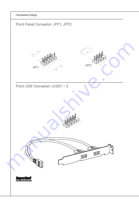
Front Panel Connector: JFP1, JFP2
Ths connector s for electrcal connecton to the front panel swtches and LEDs. The
JFP1 s complant wth Intel
®
Front Panel I/O Connectvty Desgn Gude.
1.+
3.-
10.N
o Pin
5.-
Rese
t Sw
itch
HDD
LED
Pow
er Sw
itch
Pow
er LE
D
7.+
9.Re
serve
d
8.-
6.+
4.-
2.+
JFP1
1.Gro
und
3.Su
spen
d LE
D
5.Po
wer L
ED
7.No
Pin
8.+
6.-
4.+
2.-
Buzz
er
Spea
ker
JFP2
Front USB Connector: JUSB1 ~ 3
Ths connector, complant wth Intel
®
I/O Connectvty Desgn Gude, s deal for con-
nectng hgh-speed USB nterface perpherals such as USB HDD, dgtal cameras, MP3
players, prnters, modems and the lke.
USB 2.0 Bracket (optonal)
1.VC
C
3.US
BD-
10.U
SBO
C
5.US
BD+
7.Gro
und
9.No
Pin
8.Gro
und
6.US
BD+
4.US
BD-
2.VC
C
Important
Note that the pns of VCC and GND must be connected correctly to avod possble
damage.
Summary of Contents for NF720DT-C43 Series
Page 1: ... NF720DT C43 series MS 7511 v1 x Mainboard G52 75111X7 ...
Page 10: ......
Page 16: ......
Page 54: ......
Page 57: ...A 3 MS 7511 Click Finish to restart the system 4 Click here Select this option Click here ...
Page 104: ......


