background image

2-7

Hardware  Setup

Memory

DDR2

240-pin, 1.8V

1

 DIMM1

 DIMM2

 DIMM3

 DIMM4

2

 DIMM1

 DIMM2

 DIMM3

 DIMM4

3

 DIMM1

 DIMM2

 DIMM3

 DIMM4

Dual-Channel Memory Population Rules

In Dual-Channel mode, the memory modules can transmit and receive data with two
data bus lines simultaneously. Enabling Dual-Channel mode can enhance the system
performance. Please  refer  to the following  illustrations  for  population rules under
Dual-Channel mode.

64x2=128  pin

56x2=112  pin

Empty

Installed

These DIMM slots are used for installing memory modules.
For more information on compatible components, please visit 

http://global.msi.com.

tw/index.php?func=testreport

7510v1.0_2_Hardware.p65

 2008/1/7, 

下午

 02:44

7

Summary of Contents for P7N DIAMOND - Motherboard - ATX

Page 1: ...i P7N Diamond series MS 7510 v1 X Mainboard G52 75101X1...

Page 2: ...s of Intel Corporation PS 2 and OS 2 are registered trademarks of International Business Machines Corporation W indows 95 98 2000 NT XP Vista are registered trademarks of Microsoft Corporation Netware...

Page 3: ...ace the power cord such a way that people can not step on it Do not place anything over the power cord 8 Always Unplug the Power Cord before inserting any add on card or module 9 All cautions and warn...

Page 4: ...interference by one or more of the measures listed below Reorient or relocate the receiving antenna Increase the separation between the equipment and receiver Connect the equipment into an outlet on...

Page 5: ...v WEEE Waste Electrical and Electronic Equipment Statement...

Page 6: ...vi...

Page 7: ...vii...

Page 8: ...2 Hardware Setup 2 1 Quick Components Guide 2 2 CPU Central Processing Unit 2 3 Memory 2 7 Power Supply 2 9 Back Panel 2 11 Connectors 2 13 Button 2 21 Slots 2 22 LED Status Indicators 2 27 Chapter 3...

Page 9: ...on B 2 RAID Configuration B 3 Installing Driver B 7 NVIDIA IDE Drive RAID Utility Installation B 9 Using the NVMediaShield Software B 12 Appendix C Dual Core Center C 1 Activating Dual Core Center C 2...

Page 10: ...mainboard The P7N Diamond Series mainboards are based on nVIDIA nForce 780i SLI 570i SLI chipsets for optimal system efficiency Designed to fit the advanced Intel Core 2 Extreme Quad Duo Pentium 4 D L...

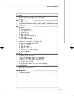
Page 11: ...667 800 1066 SDRAM 8GB Max 4 DDR2 DIMMs 240pin 1 8V For more information on compatible components please visit http global msi com tw index php func testreport LAN Supports Daul 10 100 1000 Fast Ethe...

Page 12: ...port 1 Clear CMOS button On Board Pinheaders Connectors 2 USB 2 0 pinheaders 4 ports 1 chassis intrusion 1 1394 pinheader 6 SATAII connectors 1 serial port pinheader COM1 1 TPM pinheader Slots 4 PCI...

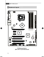
Page 13: ...4_1 JUSB2 JUSB1 JPW2 SYSFAN1 CPUFAN1 RTL8211BL RTL8211BL JMB381 JMB363 POWER1 RESET1 JSPI1 JTPM1 JCOM1 PCI_E6 PCI_E5 PCI1 PCI_E1 PCI_E2 PCI_E3 PCI_E4 FDD1 SYSFAN4 JC I1 SATA3_4 SATA1_2 SATA5_6 Top mou...

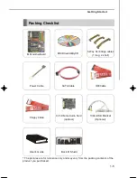
Page 14: ...ard MSI Driver Utility CD The pictures are for reference only and may vary from the packing contents of the product you purchased 3 Way SLI bridge cables 1 long 2 short Back IO Shield 1394 USB Bracket...

Page 15: ...dures While doing the installation be careful in holding the components and follow the installation procedures For some components if you install in the wrong orientation the components will not work...

Page 16: ...1 p 2 15 CPU p 2 3 CPUFAN1 p 2 15 DDR2 p 2 7 JPWR1 p 2 9 IDE1 p 2 13 JCI1 p 2 15 SYSFAN3 p 2 15 SATA1 6 p 2 14 SYSFAN2 p 2 15 JFP1 p 2 18 JFP2 p 2 18 RESET1 p 2 20 POWER1 p 2 20 Slots p 2 21 JTPM1 p 2...

Page 17: ...le replacing the CPU always turn off the ATX power supply or unplug the power supply s power cord from the grounded outlet first to ensure the safety of CPU Overclocking This mainboard is designed to...

Page 18: ...to protect the contact from damage Before you install the CPU always cover it to protect the socket pin CPU Cooler Installation When you are installing the CPU make sure the CPU has a cooler attached...

Page 19: ...me Be sure to grasp on the edge of the CPU base Note that the align ment keys are matched 8 Cover the load plate onto the package 7 Visually inspect if the CPU is seated well into the socket If not ta...

Page 20: ...orrect di rection marked on it to lock the hooks 9 Press down the load lever lightly onto the load plate and then se cure the lever with the hook under retention tab locking switch Important 1 Read th...

Page 21: ...and receive data with two data bus lines simultaneously Enabling Dual Channel mode can enhance the system performance Please refer to the following illustrations for population rules under Dual Channe...

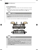
Page 22: ...successful system boot up always insert the memory modules into the DIMM1 first Installing DDR2 Modules 1 The memory module has only one notch on the center and will only fit in the right orientation...

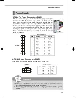
Page 23: ...llows you to connect an ATX 24 pin power supply To connect the ATX 24 pin power supply make sure the plug of the power supply is inserted in the proper orientation and the pins are aligned Then push d...

Page 24: ...y modules under S5 power off states and the power code is plugged while installing modules Due to several pins are very sensitive to ESD so this kind of memory replacement actions might cause system c...

Page 25: ...on to the Local Area Network LAN You can connect a network cable to it Keyboard Mouse 1394 Port eSATA Port LANs USB Ports USB Port The USB Universal Serial Bus port is for attaching USB devices such a...

Page 26: ...tery to keep the system configuration data With the CMOS RAM the system can automati cally boot OS every time it is turned on If you want to clear the system configuration use the button to clear data...

Page 27: ...This connector supports IDE hard disk drives optical disk drives and other IDE devices Important If you install two IDE devices on the same cable you must configure the drives separately to master sl...

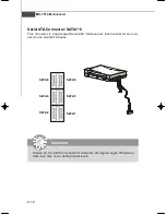
Page 28: ...nnector is a high speed Serial ATA interface port Each connector can con nect to one Serial ATA device SATA3 SATA4 SATA6 SATA5 SATA2 SATA1 Important Please do not fold the Serial ATA cable into 90 deg...

Page 29: ...ys note that the red wire is the positive and should be connected to the 12V the black wire is Ground and should be connected to GND If the mainboard has a System Hardware Monitor chipset on board you...

Page 30: ...eed USB interface peripherals such as USB HDD digital cameras MP3 players printers modems and the like PIN SIGNAL PIN SIGNAL 1 VCC 2 VCC 3 USB0 4 USB1 5 USB0 6 USB1 7 GND 8 GND 9 Key no pin 10 USBOC P...

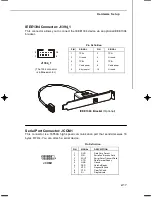
Page 31: ...acket Optional The 1394 connector is in Green color J1394_1 1 9 2 10 Serial Port Connector JCOM1 This connector is a 16550A high speed communication port that sends receives 16 bytes FIFOs You can att...

Page 32: ...with Intel Front Panel I O Connectivity Design Guide 1 2 9 10 JFP1 HDD LED Reset Switch Power LED Power Switch 7 8 Power LED Speaker 1 2 JFP2 PIN SIGNAL DESCRIPTION 1 HD_LED Hard disk LED pull up 2 F...

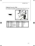
Page 33: ...for more details and usages Pin Signal Description Pin Signal Description 1 LCLK LPCclock 2 3V_STB 3Vstandbypower 3 LRST LPCreset 4 VCC3 3 3Vpower 5 LAD0 LPC address data pin0 6 SIRQ Serial IRQ 7 LAD...

Page 34: ...will explain how to change your motherboard s function through the use of button Power Button POWER1 This power button is used to turn on or turn off the system Press the button to turn on or turn off...

Page 35: ...orts up to 4 0 GB s transfer rate The PCI Express x 8 supports up to 2 0 GB s transfer rate The PCI Express x 1 supports up to 250 MB s transfer rate Mazarine PCI Express x16 Slots support PCI Express...

Page 36: ...Important Before you configure the 3 SLI platform hardware please make sure that 1 The three graphics cards have to support 3 Way SLI technology and they are of the same brand and specifications 2 Th...

Page 37: ...les are required to connect the golden fingers on the top of these three graphics cards fig 1 Please note that although you have installed three graphics cards only the video outputs on the first card...

Page 38: ...l this graphics card in mazarine PCIE x16 PCI_E1 slot to run full x16 speed 3 If you wish to use 2 way SLI you must install the two graphics cards in mazarine PCIE x16 slots PCI_E1 PCE_E4 Then connect...

Page 39: ...ol Panel Go to 3D Settings Set SLI configuration and check Enable SLI technology recommended Then press Apply concerning the details of multi GPU settings please refer to your graphics card manual Imp...

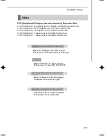
Page 40: ...nounced I R Q are hardware lines over which devices can send interrupt signals to the microprocessor The PCI IRQ pins are typically connected to the PCI bus pins as follows Order 1 Order 2 Order 3 Ord...

Page 41: ...unctional PCIE6_LED1 Lights when PCI_E6 slot is functional DIMM1_LED1 Lights when DIMM1 slot is functional DIMM2_LED1 Lights when DIMM2 slot is functional DIMM3_LED1 Lights when DIMM3 slot is function...

Page 42: ...IOS Setup program and allows you to configure the system for optimum use You may need to run the Setup program when An error message appears on the screen during the system booting up and requests you...

Page 43: ...HOENIX 2nd 5th digit refers to the model number 6th digit refers to the chipset as I Intel N nVidia and V VIA 7th 8th digit refers to the customer as MS all standard customers V1 0 refers to the BIOS...

Page 44: ...Then you can use the control keys to enter values and move from field to field within a sub menu If you want to return to the main menu just press the Esc General Help F1 The BIOS setup program provid...

Page 45: ...se this menu to specify your settings for integrated peripherals Power Management Setup Use this menu to specify your settings for power management H W Monitor This entry shows your PC health status B...

Page 46: ...endor for stable system performance Load Optimized Defaults Use this menu to load the default values set by the mainboard manufacturer specifi cally for optimal performance of the mainboard Save Exit...

Page 47: ...n to Sat determined by BIOS Read only month The month from Jan through Dec date The date from 1 to 31 can be keyed by numeric function keys year The year can be adjusted by users Time HH MM SS This al...

Page 48: ...failure This gives you an opportunity to move data from a hard disk that is going to fail to a safe place before the hard disk becomes offline Floppy Drive A This item allows you to set the type of f...

Page 49: ...Lock key when the system is powered on Setting to Off will allow users to use the arrow keys on the numeric keypad IOAPIC Function This field is used to enable or disable the APIC Advanced Programmab...

Page 50: ...erflow attacks when combined with a supporting operating system This functionality allows the processor to classify areas in memory by where application code can execute and where it cannot When a mal...

Page 51: ...k operating system Boot From Other Device Setting the option to Yes allows the system to try to boot from other device if the system fails to boot from the 1st 2nd 3rd boot device Trusted Computing Pr...

Page 52: ...he onboard 2nd LAN controller LAN Option ROM This item is used to decide whether to invoke the Boot ROM of the LAN controller Onboard IEEE1394 Controller This item allows you to enable disable the onb...

Page 53: ...you to enable disable BIOS to used PCI busmastering for reading writing to IDE drives On Chip SATA Controller This item allows you to enable disable the SATA controller RAID Mode This item allows you...

Page 54: ...ting of this field Set tings are S1 The S1 sleep mode is a low power state In this state no system context is lost CPU or chipset and hardware main tains all system context S3 The S3 sleep mode is a l...

Page 55: ...r interrupt occurred Wake Up Event Setup Press Enter and the following sub menu appears Resume From S3 By USB Device The item allows the activity of the USB device to wake up the system from S3 Suspen...

Page 56: ...aving modes through any event on PCI Express device Resume by Onbaord LAN When set to Enabled the feature allows your system to be awakened from the power saving modes through any event on LAN device...

Page 57: ...ue here If the current CPU fan temperature reaches to the target value the smart fan function will be activated It provides several sections to speed up for cooling down automaticlly CPU Fan Tolerance...

Page 58: ...he selection and not enter a password To clear a set password just press Enter when you are prompted to enter the password A message will show up confirming the password will be disabled Once the pass...

Page 59: ...automatically When the motherboard detects CPU is running programs it will speed up CPU automatically to make the program run smoothly and faster When the CPU is temporarily suspending or staying in t...

Page 60: ...em is used to switch the following two items FSB Clock MHz When the System Clock Mode sets to Auto the field is adjustable This item allows you to select the CPU Front Side Bus clock frequency in MHz...

Page 61: ...le This item controls the number of cycles for Row Address Strobe RAS to be allowed to precharge If insufficient time is allowed for the RAS to accumulate its charge before DRAM refresh refreshing may...

Page 62: ...rate Selecting 2T makes SDRAM signal controller run at 2T rate Adjust PCI E Frequency This field allows you to select the PCIE frequency in MHz Auto Disabled DRAM PCI Frequency When set to Enabled th...

Page 63: ...ecause even a slight jitter can introduce a temporary boost in clock speed which may just cause your overclocked processor to lock up NB GTL Reference Voltage This item allows you to set the NB GTL Re...

Page 64: ...etup Save Settings 1 2 Select this item and press Enter to save any changes you have made to your current settings Load Settings 1 2 Select this item and press Enter to load settings from the store Us...

Page 65: ...ard The Fail Safe Defaults are the default values set by the BIOS vendor for stable system performance When you select Load Fail Safe Defaults a message as below appears Selecting Ok and pressing Ente...

Page 66: ...l SPDIF audio effect and allows users to attach 2 4 6 or 8 speakers for better surround sound effect This manual will tell you about the specifications of the card how to install it to a mainboard how...

Page 67: ...ets pre configurable modes simulating various acoustic environments Optimized settings for headphones stereo 4 1 5 1 6 1 or 7 1 speakers Creative Multi Speaker Surround CMSS technology transforms all...

Page 68: ...r Centre Subwoofer or Headphone out Line In Microphone In S PDIF In and S PDIF Out Auxiliary Audio in Works with the Following Standards Windows XP SP2 and Vista Sound Blaster MIDI and General MIDI Mi...

Page 69: ...Audio Card to the PCI E slot and secure the card bracket with a screw 6 Replace and secure the case Reconnect the power cord to the computer Select Audio Controller If your mainboard integrates audio...

Page 70: ...els Connecting the Speakers When you have set the Multi Channel Audio Function mode properly in the software utility connect your speakers to the correct jacks in accordance with the setting in softwa...

Page 71: ...put Refer to the diagram and caption for the function of each jack on the back panel when 8 Channel Mode is selected 6 Channel Analog Audio Output 1 S PDIF Out Optical 2 MIC Line In 3 Line Out Front c...

Page 72: ...ws XP VISTA Install Windows XP Service Pack 1 for Windows XP before installing the driver The following illustrations are based on Windows XP environment and could look slightly different if you insta...

Page 73: ...e that you need from the list 3 Select your region from the list 5 On the next page click Install to start the installation and follow the setup instruc tions to complete 6 Finally you have to restart...

Page 74: ...er right corner of the screen to activate the Sound Blaster X Fi Xtreme Audio Applications simply click on each icon to enter the configuration screen Or you can move the mouse cursor to the top of sc...

Page 75: ...cher consists of various tabs such as Programs Product Settings Product Support and Companion Products In each tab you can access different applications called Tasks For more information and usage det...

Page 76: ...uter Audition presets on your computer The virtual keyboard in SFBM allows you to audition presets quickly on your computer You can also audition presets from an external MIDI device such as a MIDI ke...

Page 77: ...d audio CDs with a CD writer and print your own CD covers Organize your digital music collection with a powerful easy to use music library Search for tracks with an advanced Find feature that searches...

Page 78: ...e or speaker volume bass and treble levels Adjust volume mixer settings Configure playback settings for your speakers or headphones Adjust equalizer settings Enable environment effects Enable multicha...

Page 79: ...eaker volume Default button Click on this button to revert all the settings in Entertain ment Mode to the default Main Display button Click on this button to revert to the main display This button dis...

Page 80: ...eakers to use select the speakers type that you connected Testing your speakers click on the Channel or Noise button to test the speakers For more information and usage details on MIXER refer to its o...

Page 81: ...the CMSS 3D configuration mean by check the Enable X Fi CMSS 3D Virtual item Then you can select CMSS for multichannel audio enhancement on 4 4 1 5 1 6 1 or 7 1 speaker systems X Fi CMSS 3D Click on t...

Page 82: ...used by the world s lead ing businesses to the common PC desktop This tech nology uses multiple drives to either increase total disk space or to offer data protection For all levels RAID techniques o...

Page 83: ...ce RAID 0 Non critical data requiring high performance High data throughput No fault tolerance multiple None RAID 1 Small databases or any other small capacity environment requiring fault tolerance 10...

Page 84: ...ID 0 1 RAID 5 or JBOD and create the desired RAID array 3 Boot from the Windows CD use the floppy disk that has the RAID driver to copy and install the nForce RAID software Check p B 7 for details 4 I...

Page 85: ...digit defines the channel In the example above 1 0 means the hard drive is attached to Adapter 1 Channel 0 The following is a list of all possible combinations Serial ATA 1 0 Controller 1 Channel 0 S...

Page 86: ...KB but the values can be between 4 KB and 128 KB Assigning the Disks The disks that you enabled from the RAID Config BIOS setup page appear in the Free Disks block These are the drives that are availa...

Page 87: ...et up 3 Use the arrow keys to select the array that you want to set up then press Enter The Array Detail window appears 4 If you want to mark this disk as empty and wipe out all its contents then pres...

Page 88: ...below to make an NVIDIA RAID Driver for yourself 1 Insert the MSI CD into the CD ROM drive 2 Click the Browse CD on the Setup screen 3 Copy all the contents in the Chipset nVidia System C72 MCP55 IDE...

Page 89: ...n is completed then take out the floppy 11 Follow the instructions on how to install Windows XP After Windows XP is completely installed it is recommended that you install the the RAID manage ment too...

Page 90: ...on and install the RAID software which will upgrade the Windows SATA driver and install the RAID software 1 Start the NVIDIA nForce Drivers installation program to open the NVIDIA Windows nForce Drive...

Page 91: ...gs Control Panel then open the Administrative Tools folder and double click on Computer Management 2 Click Disk Management under the Storage section The Initialize and Convert Disk Wizards appears 3 C...

Page 92: ...he Computer Management window appears The actual disks listed will depend on your system and the unallocated partition is the total combined storage of two hard disks You must format the unallocated d...

Page 93: ...sing the NVMediaShield Software Accessing the Storage Page To access the NVIDIA Control Panel Storage page 1 Click Star Programs NVIDIA Corporation NVIDIA Control Panel Storage 2 The NVIDIA Control Pa...

Page 94: ...ray About Rebuilding Rebuilding is the process of restoring data to a hard drive from other drives in the array For example if you have a three disk RAID 5 array and one of the drives fails you will n...

Page 95: ...e dedicated disk is used by that array only when needed for example during a system crash where a RAID mirrored drive is broken The dedicated disk can be used only by the array that it is assigned to...

Page 96: ...y type to another General Migrating Requirements The new array capacity must be equal to or greater than the previous array For example it is possible to migrate from a RAID 1 array to a RAID 0 array...

Page 97: ...ns From To New Array Disk Requirements RAID 0 m n Number of disks in the new array must be greater than the original array RAID 1 m 2 n 1 RAID 1 array must include two disks converted from a one disk...

Page 98: ...ay and Migrate Array Wizard from the list of links in the Related tasks section of the side menu Instructions Click View Storage Configuration to open the associated page The View Storage Configuratio...

Page 99: ...ainboard MSI Graphics card in windows such as CPU GPU clock voltage fan speed and temperature Before you install the Dual CoreCenter please make sure the system has meet the following requirements 1 I...

Page 100: ...our mainboard path Utility MSI Utility Dual Core Center it will have an icon in the system tray a short cut icon on the desktop and a short cut path in your Start up menu You may double click on each...

Page 101: ...brand only hardware status of the MSI mainboard would be available Introduction Click each button appearing above to enter sub menu to make further configuration or to execute the function M B Click...

Page 102: ...you can adjust and monitor the fan speeds of MB and graphics card Temperature In this sub menu you can monitor the temperatures of MB and graphics card User Profile In this sub menu you can set the v...

Page 103: ...e it will restore the default settings instead Usually the Dynamic Overclocking Technology will be powered only when users PC runs huge amount of data like 3D games or video process and the motherboar...

Page 104: ...rease the clock or click the minus sign button to decrease the clock And finally click the Apply button to apply the values adjusted If you do not want to apply the adjustments click the Cancel button...

Page 105: ...age or click the minus sign button to decrease And finally click the Apply button to apply the adjustments If you do not want to apply the adjustments click the Cancel button to cancel Or click the De...

Page 106: ...section or click the minus sign button to decrease Or click the Default button to restore the default values On the underside it shows the graphs of the fan speed Only the curves of the item which the...

Page 107: ...perature In the Temperature sub menu you can see temperature status of your system On the underside it shows the graphs of the temperatures Only the curves of the item which the button is lit up with...

Page 108: ...u click the setting button that besides the user profile bar and the next screen will appear Here you can define the clock fan speed voltage by your need click the button to choose a value quickly or...

Page 109: ...draw bar to set the minimal fan speed When the fan speed is lower than the threshold you defined the system will pop up a warning message Finally you can choose the user profile by click the button in...

Reviews: