background image

4

Quick Start

Installing a Processor

1

2

3

6

4

5

7

8

9

10

11

12

13

https://youtu.be/ecdkLMmkya4 

Summary of Contents for X299M-A PRO

Page 1: ...following items If something is missing contact your dealer as soon as possible Drivers Utilities Disc Motherboard User Guide I O Shield Motherboard SATA Cable x2 Antenna x2 for AC version SLI Bridge...

Page 2: ...computer before installation is completed This could cause permanent damage to the components as well as injury to the user y If you need help during any installation step please consult a certified c...

Page 3: ...Intel LGA 2066 CPU DDR4 Memory Graphics Card SATA Hard Disk Drive SATA DVD Drive A Package of Screws Phillips Screwdriver Chassis Power Supply Unit CPU Fan Thermal Paste Quick Start Preparing Tools a...

Page 4: ...4 Quick Start Installing a Processor 1 2 3 6 4 5 7 8 9 10 11 12 13 https youtu be ecdkLMmkya4...

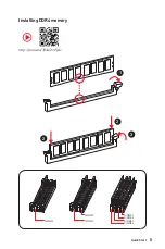
Page 5: ...5 Quick Start Installing DDR4 memory http youtu be T03aDrJPyQs 1 2 2 3 DIMMB1 DIMMB1 DIMMB2 DIMMA1 DIMMA1 DIMMA1 DIMMA2...

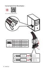
Page 6: ...9 JFP1 1 HDD LED 2 Power LED 3 HDD LED 4 Power LED 5 Reset Switch 6 Power Switch 7 Reset Switch 8 Power Switch 9 Reserved 10 No Pin R E S E T S W P O W E R S W P O W E R L E D P O W E R L E D H D D L...

Page 7: ...7 Quick Start BAT1 Installing the Motherboard 1 2...

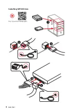
Page 8: ...8 Quick Start Installing SATA Drives http youtu be RZsMpqxythc 1 2 3 4 5...

Page 9: ...9 Quick Start Installing a Graphics Card 1 http youtu be mG0GZpr9w_A 2 3 4 5 6...

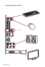
Page 10: ...10 Quick Start Connecting Peripheral Devices AC version only...

Page 11: ...11 Quick Start Connecting the Power Connectors http youtu be gkDYyR_83I4 ATX_PWR1 PCIE_PWR1 CPU_PWR1...

Page 12: ...12 Quick Start Power On 1 4 2 3...

Page 13: ...l 22 LAN Port LED Status Table 22 Audio Ports Configuration 22 Realtek HD Audio Manager 23 Installing Antennas for AC version 25 Overview of Components 26 CPU Socket 28 DIMM Slots 29 PCI_E1 3 PCIe Exp...

Page 14: ...BIOS 45 Updating BIOS 45 EZ Mode 46 Advanced Mode 48 SETTINGS 49 Advanced 49 Boot 54 Security 55 Save Exit 56 OC 58 M FLASH 66 OC PROFILE 67 HARDWARE MONITOR 68 Software Description 69 Installing Wind...

Page 15: ...Storage Technology Option ROM 88 Degraded RAID Array 91 M 2 PCIe SSD RAID 93 Intel Optane Memory Configuration 96 System Requirements 96 Installing the Intel Optane memory 96 Removing the Intel Optan...

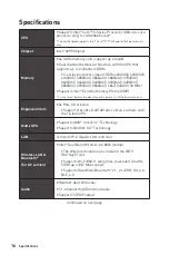
Page 16: ...y Supports Intel Extreme Memory Profile XMP For the latest information about memory please visit http www msi com Expansion Slots y 3x PCIe 3 0 x16 slots Support x16 x0 x0 x8 x8 x0 or x8 x4 x4 mode wi...

Page 17: ...ports y 2x M 2 slots Key M Supports up to PCIe 3 0 x4 and SATA 6Gb s M2_1 slot supports 2242 2260 2280 22110 storage devices M2_2 slot supports 2242 2260 2280 storage devices Intel Optane Memory Read...

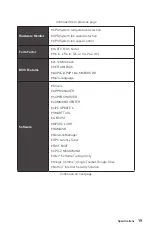
Page 18: ...onnector y 3x 4 pin system fan connectors y 1x Front panel audio connector y 2x Front panel connectors y 1x TPM module connector y 1x Chassis Intrusion connector y 1x Clear CMOS jumper y 1x Multi BIOS...

Page 19: ...BIOS Features y 2x 128 Mb flash y UEFI AMI BIOS y ACPI 6 0 PnP 1 0a SM BIOS 3 0 y Multi language Software y Drivers y APP MANAGER y SUPER CHARGER y COMMAND CENTER y LIVE UPDATE 6 y SMART TOOL y X BOOS...

Page 20: ...n Control y LED Mystic Light Extension Mystic light SYNC EZ DEBUG LED y Protection PCI E Steel Armor y Performance Multi GPU SLI Technology Multi GPU CrossFire Technology DDR4 Boost USB with type A C...

Page 21: ...IE Bus PCIE Bus PCIE Bus PS 2 Mouse Keyboard Wi Fi Bluetooth optional DMI 3 0 PCI Express Bus X299 PCH Processor NV6795 Super I O Realtek ALC1220 ASMEDIA ASM3142 S PDIF Out Line In SS Out Line Out RS...

Page 22: ...pe C LAN USB 2 0 Link Activity LED Status Description Off No link Yellow Linked Blinking Data activity Speed LED Status Description Off 10 Mbps connection Green 100 Mbps connection Orange 1 Gbps conne...

Page 23: ...volume or balance the right left side of the speakers that you plugged in front or rear panel by adjust the bar y Profiles toggles between profiles y Advanced Settings provides the mechanism to deal...

Page 24: ...Rear I O Panel AUDIO INPUT Rear Front Side Center Subwoofer Audio jacks to headphone and microphone diagram Audio jacks to stereo speakers diagram Audio jacks to 7 1 channel speakers diagram AUDIO INP...

Page 25: ...25 Rear I O Panel Installing Antennas for AC version 1 Screw the antennas tight to the Wi Fi antenna connectors as shown 2 Place the antennas as high as possible...

Page 26: ...UMP_FAN1 SYS_FAN1 PCIE_PWR1 PCI_E1 PCI_E2 PCI_E3 JBAT1 JTPM1 CPU Socket CPU_PWR1 M2_1 DIMMB2 DIMMB1 CPU_FAN1 JUSB2 JUSB1 JFP2 JFP1 SYSFAN2 JCI1 JLED1 SYSFAN3 JAUD1 ATX_PWR1 JUSB4 BIOS_SW1 JUSB3 POWER1...

Page 27: ...Socket 28 DIMMA1 A2 B1 B2 DIMM Slots 29 JAUD1 Front Audio Connector 38 JBAT1 Clear CMOS Reset BIOS Jumper 41 JCI1 Chassis Intrusion Connector 39 JFP1 JFP2 Front Panel Connectors 36 JLED1 RGB LED conn...

Page 28: ...k has formed a tight seal with the CPU before booting your system y Overheating can seriously damage the CPU and motherboard Always make sure the cooling fans work properly to protect the CPU from ove...

Page 29: ...less for 32 bit Windows OS due to the memory address limitation Therefore we recommended that you to install 64 bit Windows OS if you want to install more than 4GB memory on the motherboard y Some mem...

Page 30: ...ant y For a single PCIe x16 expansion card installation with optimum performance using the PCI_E1 slot is recommended y If you install a large and heavy graphics card you need to use a tool such as MS...

Page 31: ...hics cards into the PCI_E1 and PCI_E2 slots 2 Connect the two cards together using the SLI Bridge Connector 3 Connect all PCIe power connectors of the graphics cards 4 Reconnect the power cord power u...

Page 32: ...l M 2 module http youtu be JCTFABytrYA M2_1 M2_2 Installing M 2 module 1 2 3 30 3 Tighten the base screw into the hole of the distance to the M 2 slot as the length your M 2 module 4 Insert your M 2 m...

Page 33: ...transmission otherwise y SATA cables have identical plugs on either sides of the cable However it is recommended that the flat connector be connected to the motherboard for space saving purposes SATA...

Page 34: ...CIe M 2 PCIe SATA4 SATA8 SATA6 SATA2 SATA1 SATA3 SATA5 SATA7 M 2 PCIe M 2 SATA SATA4 SATA8 SATA6 SATA1 SATA3 SATA5 SATA7 1xM 2 SATA 1xM 2 PCIe 7xSATA M 2 SATA M 2 PCIe SATA4 SATA8 SATA6 SATA3 SATA2 SA...

Page 35: ...23 5V 12 3 3V 24 Ground 5 4 1 8 CPU_PWR1 1 Ground 5 12V 2 Ground 6 12V 3 Ground 7 12V 4 Ground 8 12V Important Make sure that all the power cables are securely connected to a proper ATX power supply t...

Page 36: ...Connectors These connectors allow you to connect USB 3 1 Gen1 ports on the front panel 1 10 11 20 1 Power 11 USB2 0 2 USB3_RX_DN 12 USB2 0 3 USB3_RX_DP 13 Ground 4 Ground 14 USB3_TX_C_DP 5 USB3_TX_C_...

Page 37: ...d pins must be connected correctly to avoid possible damage 1 2 14 13 1 LPC Clock 2 3V Standby power 3 LPC Reset 4 3 3V Power 5 LPC address data pin0 6 Serial IRQ 7 LPC address data pin1 8 5V Power 9...

Page 38: ...he fan connector to PWM or DC Mode PWM Mode pin definition 1 Ground 2 12V 3 Sense 4 Speed Control Signal DC Mode pin definition 1 Ground 2 Voltage Control 3 Sense 4 NC Important y You can switch betwe...

Page 39: ...chassis cover 3 Go to BIOS SETTINGS Security Chassis Intrusion Configuration 4 Set Chassis Intrusion to Enabled 5 Press F10 to save and exit and then press the Enter key to select Yes 6 Once the chass...

Page 40: ...he computer 2 Switch to the normal BIOS ROM with Multi BIOS switch 3 Insert the USB flash drive into the computer 4 Power on the computer and press Del key to enter BIOS setup during POST 5 Select the...

Page 41: ...external powered from a battery located on the motherboard to save system configuration data If you want to clear the system configuration set the jumper to clear the CMOS memory Resetting BIOS to def...

Page 42: ...the LED strip shorter than 2 meters to prevent dimming y Always turn off the power supply and unplug the power cord from the power outlet before installing or removing the RGB LED strip y Please use...

Page 43: ...the corresponding LED stays lit until the problem is solved CPU indicates CPU is not detected fail or non supported DRAM indicates DRAM is not detected or fail VGA indicates GPU is not detected or fai...

Page 44: ...wing methods to enter BIOS setup y Press Delete key when the Press DEL key to enter Setup Menu F11 to enter Boot Menu message appears on the screen during the boot process y Use MSI FAST BOOT applicat...

Page 45: ...nter the BIOS Setup during POST 2 Insert the USB flash drive that contains the update file into the computer 3 Select the M FLASH tab and click on Yes to reboot the system and enter the flash mode 4 S...

Page 46: ...cle to select the X M P profile This switch will only be available if the X M P supported memory module is installed y Setup Mode switch press this tab or the F7 key to switch between Advanced mode an...

Page 47: ...ardware Monitor menu that allows you to manually control the fan speed by percentage y Favorites press the Favorites tab or the F3 key to enter Favorites menu It allows you to create personal BIOS men...

Page 48: ...the descriptions of EZ Mode Overview section y BIOS menu selection the following options are available SETTINGS allows you to specify the parameters for chipset and boot devices OC allows you to adju...

Page 49: ...ween time elements The time format is hour minute second f SATA PortX M2_X Shows the information of connected SATA M 2 devices Important If the connected SATA device is not displayed turn off computer...

Page 50: ...SB and audio Press Enter to enter the sub menu fOnboard LAN Controller Onboard LAN Controller2 Enabled Enables or disables the onboard LAN controller onboard LAN controller2 fLAN Option ROM Disabled E...

Page 51: ...Ax Hot Plug Disabled Allows user to enable or disable the SATA hot plug support Enabled Enables hot plug support for the SATA ports Disabled Disables hot plug support for the SATA ports fHD Audio Cont...

Page 52: ...r to enter the sub menu fWindows 10 WHQL Support Disabled Enables the supports for Windows 10 or disables for other operating systems Before enabling this item make sure all installed devices utilitie...

Page 53: ...Sets system wake up behaviors for different sleep modes Press Enter to enter the sub menu fWake Up Event By BIOS Selects the wake up event by BIOS or operating system BIOS Activates the following ite...

Page 54: ...system wake up by PS 2 keyboard Any Key Enables the system to be awakened from S3 S4 S5 state when activity of any key on PS 2 keyboard is detected Hot Key Enables the system to be awakened from S3 S4...

Page 55: ...matically by BIOS when Windows 10 WHQL Support is enabled UEFI Enables UEFI BIOS boot mode support only LEGACY UEFI Enables both Legacy BIOS boot mode and UEFI BIOS boot mode f FIXED BOOT ORDER Priori...

Page 56: ...ets TPM Trusted Platform Module function fSecurity Device Support Disabled Enables or disables the TPM function to build the endorsement key for accessing the system fTPM Device Selection PTT Selects...

Page 57: ...Discard all changes and restore to the previous values f Restore Defaults Restore or load all default values f Boot Override The installed bootable devices will appear on this menu you can select one...

Page 58: ...CPU Ratio Apply Mode All Core Sets applied mode for CPU ratio This item only appears when a CPU that supports Turbo Boost is installed All Core Enables the CPU Ratio All CPU cores will run the same CP...

Page 59: ...PU loading f CPU Ratio Offset When Running AVX Auto Sets a offset value to lower the CPU core ratio It could be helpful for heat dissipation when running AVX instruction set If set to Auto BIOS will c...

Page 60: ...ro le of memory module for overclocking the memory This item will be available when the memory modules that support X M P is installed f DRAM Reference Clock Auto Sets the DRAM reference clock The val...

Page 61: ...l Auto These options allows you to set the voltages related to CPU If set to Auto BIOS will set these voltages automatically or you can set it manually f DRAM Voltages control Auto These options allow...

Page 62: ...reading technology Disabled Disables this item if the system does not support HT function fActive Processor Cores Control Disabled Enables or disables the following items Core0 X fCore0 X Enabled Allo...

Page 63: ...tect the CPU from overheating Enabled Throttles down the CPU core clock speed when the CPU is over the adaptive temperature Disabled Disables this function fIntel C State Auto Enables or disables the...

Page 64: ...U package in Turbo Boost mode When the current is over the speci ed value the CPU will automatically reduce the core frequency for reducing the current fCPU Over Temperature Protection Auto Sets the t...

Page 65: ...power on Lower FCLK frequency may help you to set higher base clock frequency This item only appears when a CPU that support this function is installed fDMI Link Speed Auto Sets DMI speed This item o...

Page 66: ...he update file into the computer 2 Click on M FLASH tab a demand message will be prompted Click on Yes to reboot and enter the flash mode 3 The system will enter the flash mode and a file selection me...

Page 67: ...he current overclocking pro le fLoad Overclocking Profile 1 2 3 4 5 6 Load the current overclocking pro le fClear Overclocking Profile 1 2 3 4 5 6 Clear the current overclocking profile f OC Pro le Lo...

Page 68: ...up down Smart Fan Mode field allows you to drag the gradient points to configure the fan target speeds for Smart Fan mode Smart Fan can control the fan speed automatically depending on the CPU temper...

Page 69: ...Driver Disc into your optical drive 3 The installer will automatically appear and it will find and list all necessary drivers 4 Click Install button 5 The software installation will then be in progre...

Page 70: ...been installed successfully and it is available Double click on desired icon to access the application A refresh icon shows to inform you that the application has a update version Gray icon the icon w...

Page 71: ...ation tabs at the top You can click the tab to switch the control panel y Live Update When you launch LIVE UPDATE 6 you will see the Live update tab at first This tab allows you to select files to dow...

Page 72: ...he bottom 6 When Save Path prompt you can specify a download directory 7 When downloading you will see the screen below It may take several moments to complete the process 8 To install the application...

Page 73: ...trol Panel Previous Feature Next Feature Profile Buttons Option Buttons Page Indicator Resize Corner Profile Buttons y Default load the default values for the current feature y Apply apply your change...

Page 74: ...temperature The white dot will create strip chart in real time y System Fan Button to open the system fan control panel in new window y Fan Tune Button to automatically optimize the smart fan setting...

Page 75: ...ng button The Record Warning and Mobile Control icons will appear y Record allows you to monitor the status of voltage fan speed and temperature in real time To filter record charts select the check b...

Page 76: ...vate Wi Fi on your mobile device and connect to SoftAP with the SSID 6 Run MSI COMMAND CENTER APP on your mobile device 7 Find the IP address on the SoftAP Management Setting area and enter the IP add...

Page 77: ...meet your current system environment or support faster storage access speed for your external storage or memory cards Easy In Easy page you can select one system performance mode to meet the current s...

Page 78: ...y USB SPEED UP supports faster data transfer rates of the USB storage devices y STORAGE BOOST supports faster access speed of storage device y VR BOOST provides the optimized settings to boost the sys...

Page 79: ...es will be controlled by the main screen y Live Preview gives you the full experience of your configuration s look feel while you are editing it y Light Effect Options allow you to customize lighting...

Page 80: ...ct of the motherboard y Motherboard Name shows the name of the motherboard y Live Preview gives you the full experience of your configuration s look feel while you are editing it y Light Effect Option...

Page 81: ...dows installation USB drive Step1 Choose source folder y In the Source folder box type the name and path of your Windows ISO file or click Browse button and select the file from the dialog box This op...

Page 82: ...ID in Windows system To create a software RAID 1 Use checkboxs to select the disks you want included in your RAID 2 Choose Speed Up or Backup for RAID type y Speed Up RAID0 y Backup RAID1 3 Click Star...

Page 83: ...etter Name Size and Format of the RAM disk y Option select browser temporary files to save load on the RAM disk You can also add software files to improve reading speed y Backup specify backup and res...

Page 84: ...cations by total traf c allows you to monitor network bandwidth usage y Network Test allows you to setup bandwidth control y Advanced Setting allows you to expand RWIN to accelerate download speed You...

Page 85: ...e follow the steps below 1 1 Click the Network Test block in NETWORK MANAGER 2 3 4 2 Click Test Network Speed button The test takes several minutes to test your network speed 3 Enter the testing resul...

Page 86: ...e form Stress Test tests the stability of your system Benchmarking analyzes and compares your system s performance against other system profiles Profiles manages sets of system settings y Tuning Contr...

Page 87: ...manufacturer model name chipset BIOS version and graphic interface y Memory Tab shows memory type memory size channels memory frequency y SPD Tab shows specifications relating to each memory module co...

Page 88: ...ead performance Excellent OK Good OK Write performance Excellent Good OK Good Capacity utilization 100 50 67 1 1 n 50 Using Intel Rapid Storage Technology Option ROM First you need to set the SATA mod...

Page 89: ...sing the upper arrow or down arrow keys to scroll through the available values and pressing the Enter key to select and advance to the next field The available values range from 4KB to 128 KB in power...

Page 90: ...e deletion Resetting Disks to Non RAID Select option Reset Disks to Non RAID from the main menu screen and press Enter to delete the RAID volume and remove any RAID structures from the drives Use the...

Page 91: ...s Menu ENTER Select 1 Enable Only Recovery Disk 2 Enable Only Master Disk Recovery mode will change from Continuous Update to On Request after you enable Only Recovery Disk or Only Master Disk Degrade...

Page 92: ...2 XXXX XXXXXXXX XXXXXXXXXXXXXX XXX XGB Non RAID Disk Select ESC Exit ENTER Select Menu 1 Create RAID Volume 2 Delete RAID Volume Degraded volume and disk available for rebuilding detected Selecting a...

Page 93: ...2 Optane Genie 1 Access the BIOS setup 2 Enable M 2 Optane Genie by clicking the M 2 Optane Genie item 3 Click Ok in the dialog 4 Press F10 to save configuration and exit Creating a M 2 PCIe SSD RAID...

Page 94: ...pe Select Disks PCIe XXXXX XXXXXXXX XXXX XXXGB X PCIe XXXXX XXXXXXXX XXXX XXXGB X Strip Size XXKB Capacity MB XXXXXX Create Volume 13 Enter in a volume name 14 Select the RAID level 15 Use Space key t...

Page 95: ...2 PCIe SSD RAID Volume with UEFI BIOS 1 Access the BIOS setup 2 Switch to Advanced Mode by pressing F7 key 3 Go to Settings Advanced Intel R Rapid Storage Technology 4 Select a RAID volume and press...

Page 96: ...mode y Intel Optane Memory Module Installing the Intel Optane memory 1 Update BIOS refer to the Updating BIOS section 2 Install the Intel Optane memory module Power off the system Refer to the Specif...

Page 97: ...alog Reboot System WARNING Once you enable Intel Optane memory in order to prevent seriously damage your operating system please follow the cautions listed below y DO NOT set the SATA mode back to AHC...

Page 98: ...tel Optane memory 1 Disable Intel Optane Memory Disable Intel Optane Memory via the Intel Optane memory application Intel Rapid Storage Technology Click Yes in the dialog Reboot System 2 Disable M 2 O...

Page 99: ...ck to AHCI mode that may cause operating system damage MSI has developed a software assistance for this problem You can disable Intel Optane Memory and switch back to AHCI mode while keep the system b...

Page 100: ...nd then restart the computer y If 1 long 2 short beeps are heard remove and reinstall the graphics card and then restart the computer y Test with another known working graphics card The computer does...

Page 101: ...ed using applicable European Harmonized Standards The point of contact for regulatory matters is MSI MSI NL Eindhoven 5706 5692 ER Son B B B VCCI B C Tick Compliance Battery Information European Union...

Page 102: ...n wil MSI u eraan herinneren dat De richtlijn van de Europese Unie EU met betrekking tot Vervuiling van Electrische en Electronische producten 2002 96 EC die op 13 Augustus 2005 in zal gaan kunnen nie...

Page 103: ...C 0950 2006 7 1 http www msi com html popup csr cemm_jp html http tw msi com html popup csr_tw cemm_jp html India RoHS This product complies with the India E waste Management and Handling Rule 2011 a...

Page 104: ...your system and no solution can be obtained from the user guide please contact your place of purchase or local distributor Alternatively please try the following help resources for further guidance y...

Reviews: