2-18
Hardware Setup
MS-7522
Chapter 2
Hardware Setup
MS-7522
Chapter 2
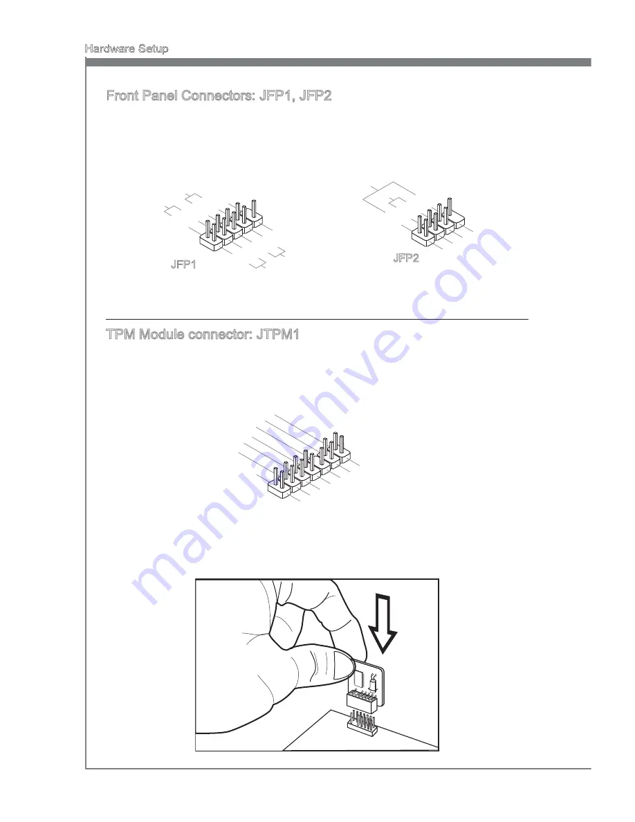
Front Panel Connectors: JFP1, JFP2
These connectors are for electrical connection to the front panel switches and LEDs.
The JFP1 is compliant with Intel
®
Front Panel I/O Connectivity Design Guide.
1.Gro
und
3.Su
spen
d LE
D
5.Po
wer L
ED
7.No
Pin
8.+
6.-
4.+
2.-
Buzz
er
Spea
ker
1.+
3.-
10.N
o Pin
5.-
Rese
t Sw
itch
HDD
LED
Pow
er Sw
itch
Pow
er LE
D
7.+
9.Re
serve
d
8.-
6.+
4.-
2.+
JFP1
JFP2
TPM Module connector: JTPM1
This connector connects to a TPM (Trusted Platform Module) module (optional). Please
refer to the TPM security platform manual for more details and usages.
10.N
o Pin
14.G
roun
d
8.5V
Pow
er
12.G
roun
d
6.Se
rial IR
Q
4.3.3
V Po
wer
2.3V
Stan
dby p
ower
1.LP
C Clo
ck
3.LP
C Re
set
5.LP
C ad
dres
s & d
ata p
in0
7.LP
C ad
dres
s & d
ata p
in1
9.LP
C ad
dres
s & d
ata p
in2
11.L
PC a
ddre
ss &
data
pin3
13.L
PC F
ram
e


