background image

Ru-33

Русский

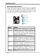
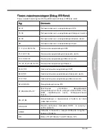
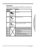
Панель индикаторов загрузки (Debug LED Panel)

Коды  индикатора загрузки (Debug LED) перечислены в таблице ниже.

Код

Состояние

02,07

Питание включено - инициализация CPU

03,08

Питание включено - инициализация Северного моста

04,09

Питание включено - инициализация Южного моста

0B

Питание включено - инициализация Кэша

11~14,32~36,56~5A

Начальная инициализация CPU

15~18,37~3A

Начальная инициализация Северного моста

19~1C,3B~3E

Начальная инициализация Южного моста

1D~2F,31,3F~4E,50~55 Начальная инициализация Памяти

63~67,D0

Заключительная инициализация CPU

69~6F,D1

Заключительная инициализация Северного моста

70~77,D2

Заключительная инициализация Южного моста

92~96,B5,D4

Инициализация шины PCI

97,98,99,B2,D5~D7

Консольные 

устройства 

Ввода/Вывода/ 

Инициализация консоли и загрузка Opton ROM (VGA, 

RAID,  параллельные  порты,  последовательные 

порты……)

9A~A7,B4

Инициализация  и  определения  устройств  на  плате 

(USB/ SATA/ SCSI……)

A8,A9,AB

Начало  настройки.  Настройка  BIOS    по  запросу  /

необходимости.

AD/AE

Событие  готовности  к  загрузке/Событие  загрузки  с 

Legacy устройств

AA

Вход в ОС (Wndows

®

 7 или Wndows

®

 XP).

Summary of Contents for X79A-GD45 series

Page 1: ...X79A GD65 8D series MS 7760 v1 x Mainboard G52 77601X2 Europe version...

Page 2: ...istered trademarks of AMD Corporation Intel is registered trademarks of Intel Corporation Windows is registered trademarks of Microsoft Corporation AMI is registered trademark of American Megatrends I...

Page 3: ...ment from overheating DO NOT COVER THE OPENINGS Make sure the voltage of the power source is at 110 220V before connecting the equipment to the power inlet Place the power cord such a way that people...

Page 4: ...ct the interference by one or more of the measures listed below Reorient or relocate the receiving antenna Increase the separation between the equipment and receiver Connect the equipment into an outl...

Page 5: ...rotection waste batteries should be collected separately for recycling or special disposal European Union Batteries battery packs and accumulators should not be disposed of as unsorted household waste...

Page 6: ...ronik Altger te nicht mehr als kommunale Abf lle entsorgt werden MSI hat europaweit verschiedene Sammel und Recyclingunternehmen beauftragt die in die Europ ische Union in Verkehr gebrachten Produkte...

Page 7: ...n voor de producten die de merknaam MSI dragen en verkocht zijn in de EU Deze goederen kunnen geretourneerd worden op lokale inzamelingspunten SRPSKI Da bi za titili prirodnu sredinu i kao preduze e k...

Page 8: ...ch sb rn ch MAGYAR Annak rdek ben hogy k rnyezet nket megv dj k illetve k rnyezetv d k nt fell pve az MSI eml kezteti nt hogy Az Eur pai Uni EU 2005 augusztus 13 n hat lyba l p az elektromos s elek tr...

Page 9: ...tions En 2 Connectors Quick Guide En 4 Back Panel Quick Guide En 6 CPU Central Processing Unit En 8 Mounting Screw Holes En 12 Power Supply En 13 Memory En 14 Expansion Slots En 18 Internal Connectors...

Page 10: ...u panneau arri re Fr 6 Processeur CPU Fr 8 Trous Taraud s de Montage Fr 12 Connecteurs d alimentation Fr 13 M moire Fr 14 Emplacements d extension Fr 18 Connecteurs internes Fr 19 Boutons Fr 27 Cavali...

Page 11: ...English X79A GD65 8D Series...

Page 12: ...AN Supports LAN 10 100 1000 Fast Ethernet by Intel 82579 IEEE 1394 Integrated chip by VIA VT6315N Supports 1x IEEE 1394 port back panel 1x IEEE 1394 connector Audio Integrated HD audio codec by Realte...

Page 13: ...s On Board 2x USB 2 0 connectors 1x USB 3 0 connector 1x IEEE 1394 connector 1x Front Panel Audio connector 1x Chassis Intrusion connector 1x Power button 1x OC Genie button 2x Direct OC buttons 1x Mu...

Page 14: ...IMM1 4 JPWR2 JPWR1 SYSFAN4 SATA1 2 JFP1 JUSB1 JAUD1 JCI1 POWER1 PCI_E1 SYSFAN2 JBAT1 JDLED3 SYSFAN3 Minus PCI_E2 PCI_E3 PCI_E4 PCI_E5 OC Genie JFP2 SYSFAN1 JTURBO1 BATT DIMM5 8 PCI_E6 JPWR3 J1394_1 Pl...

Page 15: ...tors SATA3 6 En 19 CPU Fan Power Connector CPUFAN1 En 20 System Fan Power Connectors SYSFAN1 4 En 20 Front Panel Connectors JFP1 JFP2 En 21 USB 2 0 Expansion Connectors JUSB2 JUSB3 En 22 USB 3 0 Expan...

Page 16: ...terconnect Format connector is provided for digital audio transmission to external speakers through a coaxial cable Optical S PDIF Out This S PDIF Sony Philips Digital Interconnect Format connector is...

Page 17: ...computer is communicating with another computer on the network Right Green Off 10 Mbits sec data rate On 100 Mbits sec data rate Orange On 1000 Mbits sec data rate Audio Ports These connectors are us...

Page 18: ...cord to ensure the safety of the CPU Overclocking This mainboard is designed to support overclocking Before attempting to overclock please make sure that all other system components can tolerate overc...

Page 19: ...remember to install a CPU cooler A CPU cooler is necessary to prevent overheating and maintain system stability Follow the steps below to ensure correct CPU and CPU cooler installation Wrong installat...

Page 20: ...uniform motion and latch to the socket 5 Line up the CPU to fit the CPU socket Be sure to hold the CPU by the base with the metal contacts facing downward The alignment keys on the CPU will line up wi...

Page 21: ...0 Locate the CPU fan connector on the mainboard 11 Place the heatsink on the mainboard with the fan s wires facing towards the fan connector and the screws matching the holes on the socket 12 Using a...

Page 22: ...e the mainboard with the screws provided with your computer case The locations of the screw holes on the mainboard are shown below For more information please refer to the manual that came with the co...

Page 23: ...7 G r o u n d 5 G r o u n d 1 8 G r o u n d 6 5 V 1 9 G r o u n d 7 G r o u n d 2 2 5 V 1 0 1 2 V 2 0 R e s 8 P W R O K 2 3 5 V 1 1 1 2 V 2 1 5 V 9 5 V S B 2 4 G r o u n d 1 2 3 3 V BATT ATX 8 pin Po...

Page 24: ...ata bus channels simultaneously to enhance system performance Please refer the following tables for more details Defined Channel list Channel DIMM Slot Channel A DIMM1 DIMM2 Channel B DIMM3 DIMM4 Chan...

Page 25: ...enter notch on the bottom that will only allow it to fit one way into the DIMM slot Push the memory module deep into the DIMM slot The plastic clip at one side of the DIMM slot will automatically clos...

Page 26: ...lled DIMMs 3 memory modules Diagram DIMM1 DIMM3 DIMM5 or DIMM1 DIMM5 DIMM7 or DIMM1 DIMM3 DIMM7 DIMM1 DIMM2 DIMM3 DIMM4 DIMM8 DIMM7 DIMM6 DIMM5 or DIMM1 DIMM2 DIMM3 DIMM4 DIMM8 DIMM7 DIMM6 DIMM5 or DI...

Page 27: ...s Diagram DIMM1 DIMM2 DIMM3 DIMM4 DIMM5 DIMM6 DIMM7 DIMM8 DIMM1 DIMM2 DIMM3 DIMM4 DIMM8 DIMM7 DIMM6 DIMM5 Important To ensure system stability for multi channel mode Dual Triple Quad channel mode memo...

Page 28: ...the power supply and unplug the power supply power cable from the power outlet Read the expansion card s documentation to check for any necessary additional hardware or software changes Graphics Card...

Page 29: ...rom the power supply Such devices include disk drives HDD solid state drives SSD and optical drives CD DVD Blu Ray Please refer to the device s manual for further information Many computer cases also...

Page 30: ...BATT 1 G r o u n d 2 1 2 V 3 S e n s o r 4 C o n t r o l CPUFAN1 SYSFAN1 SYSFAN2 SYSFAN3 4 BATT 1 G r o u n d 2 1 2 V 3 S e n s o r 4 N C Important Please refer to your processor s official website or...

Page 31: ...g the mConnectors into the mainboard BATT 1 3 1 0 N o P i n 5 R e s e t S w i t c h H D D L E D P o w e r S w i t c h P o w e r L E D 7 9 R e s e r v e d 8 6 4 2 JFP1 1 G r o u n d 3 S u s p e n d L E...

Page 32: ...onvert data channels to extra power channels to quickly charge your connected device Please note that when the SuperCharger application is turned on data transmission and synchronization over the JUSB...

Page 33: ...U S B 3 _ T X _ C _ D P 1 3 G r o u n d 1 2 U S B 2 0 1 1 U S B 2 0 The MB layout in this figure is for reference only USB 3 0 Bracket optional Important Note that the VCC and GND pins must be connec...

Page 34: ...e warning you must enter the BIOS utility and clear the record BATT 1 C I N T R U 2 G r o u n d Front Panel Audio Connector JAUD1 This connector allows you to connect the front audio panel located on...

Page 35: ...V C C 3 4 C o n t r o l p i n 2 C o n t r o l p i n 1 5 V S B 3 C o n t r o l p i n 5 C o n t r o l p i n 7 C o n t r o l p i n 9 G r o u n d 1 1 R e s e r v e d p i n 1 3 G r o u n d MultiConnect Pa...

Page 36: ...ry channel C and D voltage The DDR memory voltage is the voltage supplied to the DDR memory modules on the mainboard Lower memory timings may require higher voltages to maintain system stability DDR_A...

Page 37: ...ormance values To disable OC Genie power off the system and press the OC Genie button again The button will depress and the CPU configuration settings will return to normal values BATT Important Pleas...

Page 38: ...tton once to turn on or turn off the system BATT Direct OC Buttons Plus Minus These buttons are used to increase or decrease the Base clock frequency Pressing the Plus Minus button once will increase...

Page 39: ...1 1 Important You can clear the CMOS RAM by shorting this jumper while the system is off Afterwards open the jumper Do not clear the CMOS RAM while the system is on because it will damage the mainboa...

Page 40: ...ed A and B default BIOS ROM is A If one is crashed you can shift to the other for booting by sliding the switch In addition these two BIOS ROMs do not have the Auto Recovery feature you need to mainta...

Page 41: ...En 31 English LED Status Indicators BATT CPU_PHASE CPU_IO_PHASE HDD_LED Debug LED Panel CPU_SA_PHASE DDR_PHASE DrMOS_ALARM CHD_DIMM_WARNING CHB_DIMM_WARNING...

Page 42: ...ent power phase mode CPU_IO_PHASE These LEDs indicate the current CPU I O power phase mode DrMOS_ALARM This LED will light when DrMOS overheat DDR_PHASE These LEDs indicate the current memory power ph...

Page 43: ...9 1C 3B 3E Early South Bridge Initialization 1D 2F 31 3F 4E 50 55 Early Memory Initialization 63 67 D0 Late CPU Initialization 69 6F D1 Late North Bridge Initialization 70 77 D2 Late South Bridge Init...

Page 44: ...f Test process When the message below appears on the screen press DEL key to enter Setup Press DEL key to enter Setup Menu F11 to enter Boot Menu If the message disappears before you respond and you s...

Page 45: ...t recommend general users to overclock ECO This menu is related to energy saving settings BROWSER This feature is used to enter the MSI Winki web browser UTILITIES This menu contains utilities for bac...

Page 46: ...Z F6 Load optimized defaults F10 Save Change and Reset F12 Save a screenshot to a FAT FAT32 USB drive Sub Menu An arrow symbol appears to the left of certain fields that means it contains a sub menu A...

Page 47: ...current clocks of CPU and Memory speed Read only Internal PLL Overvoltage This item is used to adjust the PLL voltage CPU Base Clock MHz This item allows you to set the CPU Base clock in MHz You may o...

Page 48: ...the adjusted DRAM frequency Read only DRAM Timing Mode Select whether DRAM timing is controlled by the SPD Serial Presence Detect EEPROM on the DRAM module Setting to Auto enables DRAM timings and the...

Page 49: ...elay of different banks tRTP Time interval between a read and a precharge command tFAW This item is used to set the tFAW four activate window delay timing tWCL This item is used to set the tWCL Write...

Page 50: ...to the CPU Auto Automatically sets values for maximum stability Low VDroop Provides less fluctuation better for overclocking CPU Core Voltage System Agent Voltage SA CPU I O Voltage CPU PLL Voltage DD...

Page 51: ...is information at any time by pressing F5 Press Enter to enter the sub men DIMM1 4 Memory SPD Press Enter to enter the sub menu The sub menu displays the informations of installed memory CPU Features...

Page 52: ...in level the processor automatically reduces its clock speed For overclocking it is recommended this feature is disabled Intel C State C state is a power management state that detects when the system...

Page 53: ...Internet To update the BIOS with the Live Update utility Click Live Update button on the BIOS UTILITIES menu The Winki must be installed 1 Setup the connection by click the setting button if necessary...

Page 54: ...e Product info menu It shows the newly information of MSI product Security menu It provides the useful antivirus program Important Please visit the MSI officially website to get the latest drivers and...

Page 55: ...Deutsch X79A GD65 8D Serie...

Page 56: ...t Ethernet ber Intel 82579 IEEE 1394 Onboard Chip ber VIA VT6315N Unters tzt 2x IEEE 1394 1x onboard und 1x I O Anschluss Audio Integrierter Realtek ALC892 HD Audiocodec 8 Kanal Audio Ausgang mit Ansc...

Page 57: ...94 Stiftleiste x1 Audio Stiftleiste f r Geh use Audio Ein Ausg nge x1 Geh usekontaktschalter x1 Ein Ausschalter x1 OC Genie Taste x1 Direct OC Tasten x2 Multi BIOS Schalter x1 MultiConnect Paneelverbi...

Page 58: ...1 4 JPWR2 JPWR1 SYSFAN4 SATA1 2 JFP1 JUSB1 JAUD1 JCI1 POWER1 PCI_E1 SYSFAN2 JBAT1 JDLED3 SYSFAN3 Minus PCI_E2 PCI_E3 PCI_E4 PCI_E5 OC Genie JFP2 SYSFAN1 JTURBO1 BATT DIMM5 8 PCI_E6 JPWR3 J1394_1 Plus...

Page 59: ...TA 3Gb s Anschl sse SATA3 6 De 19 CPU L fteranschluss CPUFAN1 De 20 Stromanschl sse f r L fter SYSFAN1 4 De 20 Frontpanel Anschl sse JFP1 JFP2 De 21 USB 2 0 Erweiterungsanschl sse JUSB2 JUSB3 De 22 US...

Page 60: ...igital Interconnect Format dient als digitale Schnittstelle zur Audioausgabe zur den externen Lautsprechern durch ein Koaxialka bel Optischer S PDIF Ausgang Dieser S PDIF Ausgang Sony Philips Digital...

Page 61: ...0 MBit s An Datenrate 100 MBit s Orange An Datenrate 1000 MBit s Audioanschl sse Diese Audioanschl sse dienen zur Verbindung mit Audioger ten Durch die Farben erkennen Sie die unterschiedlichen Funkti...

Page 62: ...Motherboard wurde so entworfen dass es bertakten unterst tzt Stellen Sie jedoch bitte sicher dass die betroffenen Komponenten mit den abweichenden Einstel lungen w hrend des bertaktens zurecht kommen...

Page 63: ...aran einen CPU K hler zu installieren Ein CPU K hler ist notwendig um eine berhitzung zu vermeiden und die Systemsta bilit t beizubehalten Befolgen Sie die nachstehenden Schritte um die richtige CPU u...

Page 64: ...ierhebel und rasten Sie ihn ein 5 Positionieren Sie die CPU so dass sie auf den Sockel passt Die CPU muss dabei mit der Pin_seite nach unten zeigen Vergewissern Sie sich anhand der Justiermar kierunge...

Page 65: ...e den CPU L fteranschluss auf dem Motherboard ausfindig 11 Setzen Sie den Prozessork hler auf die K hlerhalterung des Motherboards und beachten Sie die bereinstimmung der L fterverankerungen mit den d...

Page 66: ...nboard mit den dem Geh use beiliegenden Schrauben fest Die Positionen der Befestigungsl cher sehen Sie in der Zeichnung unten Weitere Informationen erfahren Sie ber Ihr Geh usehandbuch Wichtig Install...

Page 67: ...u n d 5 G r o u n d 1 8 G r o u n d 6 5 V 1 9 G r o u n d 7 G r o u n d 2 2 5 V 1 0 1 2 V 2 0 R e s 8 P W R O K 2 3 5 V 1 1 1 2 V 2 1 5 V 9 5 V S B 2 4 G r o u n d 1 2 3 3 V BATT ATX 8 poliger Stroman...

Page 68: ...pfangen um die Systemleistung zu verbessern Ausf hrlichere Informationen entnehmen Sie bitte den folgenden Tabellen Definierte Kanalliste Kanal DIMM Steckplatz Kanal A DIMM1 DIMM2 Kanal B DIMM3 DIMM4...

Page 69: ...eine Kerbe an der Unterseite so dass es nur in einer Richtung eingesetzt werden kann Dr cken Sie die Speichermodule tief in den DIMM Steckplatz hinein Der Kunstst offb gel an jedem Ende des DIMM Steck...

Page 70: ...erten DIMMs 3 Speichermodule Abbildung DIMM1 DIMM3 DIMM5 oder DIMM1 DIMM5 DIMM7 oder DIMM1 DIMM3 DIMM7 DIMM1 DIMM2 DIMM3 DIMM4 DIMM8 DIMM7 DIMM6 DIMM5 oder DIMM1 DIMM2 DIMM3 DIMM4 DIMM8 DIMM7 DIMM6 DI...

Page 71: ...DIMM5 DIMM6 DIMM7 DIMM8 DIMM1 DIMM2 DIMM3 DIMM4 DIMM8 DIMM7 DIMM6 DIMM5 Wichtig Stellen Sie im Multi Kanal Modus Dual Triple Quad Kanal Modus bitte sicher dass Sie Module des gleichen Typs und identis...

Page 72: ...aus der Steck dose herausziehen bevor Sie eine Erweiterungskarte installieren oder entfernen Lesen Sie bitte auch die Dokumentation der Erweiterungskarte um notwendige zus tzliche Hardware oder Softw...

Page 73: ...TA4 SATA3 SATA6 SATA5 SATA8 SATA7 SATA2 SATA1 SATA7 8 6Gb s ber ASM1061 Wichtig Viele Serial ATA Ger te ben tigen eine zus tzliche Stromversorgung ber das PC Netzteil Dazu geh ren Festplatten SSD und...

Page 74: ...angeschlossen werden BATT 1 G r o u n d 2 1 2 V 3 S e n s o r 4 C o n t r o l CPUFAN1 SYSFAN1 SYSFAN2 SYSFAN3 4 BATT 1 G r o u n d 2 1 2 V 3 S e n s o r 4 N C Wichtig Informieren Sie sich vor dem K hl...

Page 75: ...ken Sie das mConnec tors in dem Mainboard BATT 1 3 1 0 N o P i n 5 R e s e t S w i t c h H D D L E D P o w e r S w i t c h P o w e r L E D 7 9 R e s e r v e d 8 6 4 2 JFP1 1 G r o u n d 3 S u s p e n...

Page 76: ...setzen um die angeschlossenen Ger te besonders schnell aufzu laden Bitte beachten Sie dass wenn die Super Charger Anwendung aktiviert ist die Daten bertragung und Synchronisation ber den JUSB3 Anschlu...

Page 77: ...out dieser Abbildung dient lediglich Illustrationszwecken USB 3 0 Slotblech optional Wichtig Bitte beachten Sie dass Sie die mit VCC Stromf hrende Leitung und GND Erdlei tung bezeichneten Pins korrekt...

Page 78: ...uf gerufen und die Aufzeichnung gel scht werden BATT 1 C I N T R U 2 G r o u n d Audioanschluss des Frontpanels JAUD1 Dieser Anschluss erm glicht den Anschluss von Audio Ein und Ausg ngen eines Frontp...

Page 79: ...V C C 3 4 C o n t r o l p i n 2 C o n t r o l p i n 1 5 V S B 3 C o n t r o l p i n 5 C o n t r o l p i n 7 C o n t r o l p i n 9 G r o u n d 1 1 R e s e r v e d p i n 1 3 G r o u n d MultiConnect Fr...

Page 80: ...nnung ist die Spannung die bei den installierten DDR Speichermodulen anliegt Niedrige DDR Timings k nnen h here Spannungen erfordern um einen stabilen Betrieb zu gew hrleisten DDR_A B Spannung des Spe...

Page 81: ...U automatisch is zu den optimalen Werten bertakten Um OC Genie zu deaktivieren dr cken Sie erneut die OC Genie Taste Die CPU Einstellungen werden dann auf die Defaultwerte zur ckgesetzt BATT Wichtig B...

Page 82: ...se Taste um das System ein bzw auszuschalten BATT Direct OC Tasten Plus Minus Diese Tasten werden benutzt um die Haupt Taktfrequenz zu erh hen oder zu verrin gern Dr cken Sie die Plus Minus Tasten ein...

Page 83: ...altet ist k nnen Sie die Steckbr cke stecken um die Daten im CMOS zu l schen Danach entfernen Sie die Steckbr cke Versuchen Sie niemals die Daten im CMOS zu l schen wenn das System eingeschaltet ist D...

Page 84: ...S ROM A Falls ein BIOS abgest rzt ist k nnen Sie durch verschieben des Schalters zum zweiten BIOS umschalten um zu starten Die beiden BIOS ROMs unterst tzen keine automatische Wiederherstellungsfunkti...

Page 85: ...De 31 Deutsch LED Statusanzeige BATT CPU_PHASE CPU_IO_PHASE HDD_LED Debug LED Panel CPU_SA_PHASE DDR_PHASE DrMOS_ALARM CHD_DIMM_WARNING CHB_DIMM_WARNING...

Page 86: ...CPU_IO_PHASE Diese LEDs zeigen die aktuelle CPU I O Leistungsphasenmodus DrMOS_ALARM Diese LED leuchtet wenn DrMOS berhitzen DDR_PHASE Diese LEDs zeigen die aktuellen Speicher Leistungsphasenmodus HDD...

Page 87: ...F 4E 50 55 Fr he Speicherinitialisierung 63 67 D0 Sp te CPU Initialisierung 69 6F D1 Sp te Northbridge Initialisierung 70 77 D2 Sp te Southbridge Initialisierung 92 96 B5 D4 PCI Bus Initialisierung 97...

Page 88: ...st Selbst berpr fung nach Anschalten Sobald die Meldung unten erscheint dr cken Sie die Taste Entf DEL um das Setup aufzurufen Press DEL key to enter Setup Menu F11 to enter Boot Menu ENTF dr cken um...

Page 89: ...Datum CPU Name CPU Frequenz DRAM Frequenz DRAM Kapazit t und die BIOS Version BIOS Men Auswahl Diese Men punkte k nnen die Men s des BIOS ausw hlen Die folgenden Optionen stehen zur Verf gung SETTINGS...

Page 90: ...ufrufen Klicken Sie auf den Eintrag um das System von dem Ger t sofort zu starten Auswahl des Modus Mit dieser Funktion k nnen Sie Voreinstellungen des Energiesparens oder bertaktung laden Men anzeige...

Page 91: ...e mit der linken Maustaste Auswahl eines Symbols Feldes Esc Klicken Sie mit der rechten Maustaste Aufruf Exit Men oder zur ck zum Hauptmen von Untermen Hochz hlen oder ndern eines Wertes Herunterz hle...

Page 92: ...ter oder doppelklicken mit der linken Maustaste in das Untermen gelangen Dort k nnen Sie mit den Steuertasten Werte eingeben und navigieren Um in das vorherige Men zu gelangen dr cken Sie Esc oder kli...

Page 93: ...ber takten die OC genie Funktion Current CPU DRAM Frequency Zeigt den derzeitigen Takt der CPU und die Geschwindigkeit des Speichers an Nur Anzeige keine nderung m glich Internal PLL Overvoltage Diese...

Page 94: ...e in offizielle Website des Intel Adjusted DRAM Frequency Zeigt die Speicherfrequenz an Nur Anzeige keine nderung m glich DRAM Timing Mode W hlen Sie aus wie das DRAM Timing durch das SPD Serial Prese...

Page 95: ...nn eines Spaltenlesebefehls Es gestattet den I O Ansteuerungssignalen die Datenwieder herstellung der Zelle vor dem Lesebefehl zu berschreiben tRRD Legt die Aktiv zu Aktiv Verz gerung f r unterschiedl...

Page 96: ...Taktsteigerung erzeugen kann die gerade ausreichen mag um Ihren bertakteten Prozessor zum einfrieren zu brin gen Vdroop Control Ladelinie Droop steuert den Stromfluss an die CPU Auto Automatisch setz...

Page 97: ...zeigt die Technologien des verwendeten Prozessors an Nur Anzeige MEMORY Z Dr cken Sie die Eingabetaste Enter um das Untermen aufzurufen Das Untermen markiert alle Einstellungen und Timings von Ihren...

Page 98: ...lle Prozessor unterst tzt Enhanced Halt Stand C1E OverSpeed Protection Die Funktion kann den aktuellen CPU Status sowie seine Leistungsaufnahme berwachen Wenn es ein bestimmtes Niveau bersteigt verrin...

Page 99: ...date Programm zu aktualisieren f hren Sie bitte folgende Schritte aus Klicken Sie auf die Taste Live Update im Men f r BIOS Dienstprogramme Die Winki muss installiert sein 1 Wenn n tig bauen Sie die V...

Page 100: ...its Men Es bietet die n tzliche Antivirenprogramm Wichtig Besuchen Sie bitte die offizielle Website des MSI um die neuesten Treiber und BIOS f r bessere System Leistung zu erhalten Installation von MS...

Page 101: ...Fran ais X79A GD65 8D S ries...

Page 102: ...e LAN 10 100 1000 Fast Ethernet par Intel 82579 IEEE 1394 Puces int gr es par VIA VT6315N Supporte 1x port IEEE 1394 panneau arri re et 1x connecteur IEEE 1394 Audio HD audio codec int gr par Realtek...

Page 103: ...2x connecteurs USB 2 0 1x connecteur USB 3 0 1x connecteur IEEE 1394 1x connecteur audio avant 1x connecteur Ch ssis Intrusion 1x bouton d alimentation 1x bouton OC Genie 2x boutons OC directs 1x inte...

Page 104: ...R2 JPWR1 SYSFAN4 SATA1 2 JFP1 JUSB1 JAUD1 JCI1 POWER1 PCI_E1 SYSFAN2 JBAT1 JDLED3 SYSFAN3 Minus PCI_E2 PCI_E3 PCI_E4 PCI_E5 OC Genie JFP2 SYSFAN1 JTURBO1 BATT DIMM5 8 PCI_E6 JPWR3 J1394_1 Plus JUSB2 J...

Page 105: ...SATA3 6 Fr 19 Connecteur d alimentation du ventilateur CPU CPUFAN1 Fr 20 Connecteurs d alimentation du ventilateur syst me SYSFAN1 4 Fr 20 Connecteurs panneau avant JFP1 JFP2 Fr 21 Connecteurs d exten...

Page 106: ...lier l interface S PDIF Sony et Philips Digital Intercon nect Format de la transmission audio num rique un haut parleur externe via un c ble coaxial S PDIF Out optique Ce connecteur est utilis pour re...

Page 107: ...lum e Clignotante L ordinateur communique avec un autre ordinateur sur le r seau local LAN Droite Vert Eteinte Un d bit de 10 Mbits sec est s lectionn Allum e Un d bit de 100 Mbits sec est s lectionn...

Page 108: ...r ou par d brancher le cordon d alimentation de la prise pour garantir la s curit du processeur Overclocking Cette carte m re supporte l overclocking N anmoins veuillez vous assurer que vos composants...

Page 109: ...ous que le CPU soit quip d un ventilateur qui est n cessaire pour viter la surchauffe et maintenir la stabilit Suivez les instruction suivantes pour installer le CPU et son ventilateur correctement Un...

Page 110: ...fermement et verrouillez le au socket 5 Alignez le CPU sur le socket CPU Assurez vous de tenir le CPU par le base avec les contacts m taux vers le bas La cl d alignement du CPU s aligne sur les bords...

Page 111: ...sez le connecteur du ventilateur de CPU sur la carte m re 11 Placez le ventilateur sur la carte m re avec les fils vers le connecteur et les vis correspondant aux trous sur le socket 12 Servez vous d...

Page 112: ...carte m re et s curisez la carte m re avec les vis fournies avec le boitier de l ordinateur L emplacement des trous taraud s de la carte est montr e ci dessous Pour plus d information veuillez vous r...

Page 113: ...G r o u n d 5 G r o u n d 1 8 G r o u n d 6 5 V 1 9 G r o u n d 7 G r o u n d 2 2 5 V 1 0 1 2 V 2 0 R e s 8 P W R O K 2 3 5 V 1 1 1 2 V 2 1 5 V 9 5 V S B 2 4 G r o u n d 1 2 3 3 V BATT Connecteur d al...

Page 114: ...x de bus donn es simultan ment pour am liorer la performance du syst me Veuillez vous r f rer au tableau suivant pour plus de d tails Liste de canal d fini Canal Emplacement DIMM Canal A DIMM1 DIMM2 C...

Page 115: ...ur le bas et ne s adaptera que s il est orient de la mani re convenable l emplacement DIMM Poussez le module de m moire profond ment dans l emplacement DIMM Les pinces plastiques de chaque c t de l em...

Page 116: ...s install s 3 modules de m moire Diagramme DIMM1 DIMM3 DIMM5 ou DIMM1 DIMM5 DIMM7 ou DIMM1 DIMM3 DIMM7 DIMM1 DIMM2 DIMM3 DIMM4 DIMM8 DIMM7 DIMM6 DIMM5 ou DIMM1 DIMM2 DIMM3 DIMM4 DIMM8 DIMM7 DIMM6 DIMM...

Page 117: ...M1 DIMM2 DIMM3 DIMM4 DIMM5 DIMM6 DIMM7 DIMM8 DIMM1 DIMM2 DIMM3 DIMM4 DIMM8 DIMM7 DIMM6 DIMM5 Important Pour assurer la stabilit du syst me au mode multi canal Mode Double Triple Quatre canal les modul...

Page 118: ...rez une carte d extension assurez vous que le PC n est pas reli au secteur Lisez la documentation pour faire les configurations n cessaires du mat riel ou logiciel ajout s Tableau d installation de ca...

Page 119: ...n Ce type de p riph riques comprend les disques durs HDD les lecteurs d tat solid SSD et les p riph riques optiques CD DVD Blu Ray Veuillez vous r f rer au manuel des p riph riques pour plus d informa...

Page 120: ...r o u n d 2 1 2 V 3 S e n s o r 4 C o n t r o l CPUFAN1 SYSFAN1 SYSFAN2 SYSFAN3 4 BATT 1 G r o u n d 2 1 2 V 3 S e n s o r 4 N C Important Veuillez vous r f rer au site officiel de votre processeur ou...

Page 121: ...nnectez les mConnectors la carte m re BATT 1 3 1 0 N o P i n 5 R e s e t S w i t c h H D D L E D P o w e r S w i t c h P o w e r L E D 7 9 R e s e r v e d 8 6 4 2 JFP1 1 G r o u n d 3 S u s p e n d L...

Page 122: ...eur Lorsque la application Super Charger est activ e le connecteur JUSB3 permettra la charge rapide Veuillez remarquer qu ce moment la transmission et synchronisation des donn es du connecteur JUSB3 s...

Page 123: ...U S B 3 _ T X _ C _ D P 1 3 G r o u n d 1 2 U S B 2 0 1 1 U S B 2 0 Le sch ma de carte m re dans la figure n est qu titre de r f rence Support USB 3 0 en option Important Notez que les pins de VCC et...

Page 124: ...s devez entrer dans le BIOS et d sactiver l alerte BATT 1 C I N T R U 2 G r o u n d Connecteur audio panneau avant JAUD1 Ce connecteur vous permet de connecter un audio sur le panneau avant Il est con...

Page 125: ...i n 6 V C C 3 4 C o n t r o l p i n 2 C o n t r o l p i n 1 5 V S B 3 C o n t r o l p i n 5 C o n t r o l p i n 7 C o n t r o l p i n 9 G r o u n d 1 1 R e s e r v e d p i n 1 3 G r o u n d Connecteur...

Page 126: ...Hub DDR_C D Tension M moire canal C et D La tension de m moire DDR est celle fournie aux modules de m moire DDR sur la carte m re Un bas timing m moire exige une haute tension pour maintenir la stabil...

Page 127: ...e teignez le syst me et appuyez encore le bouton OC Genie Le bouton n est plus enfonc et les r glages de configuration CPU retournent aux valeurs par d faut BATT Important Veuillez installer une m moi...

Page 128: ...ur allumer ou teindre le syst me BATT Boutons OC directs Plus Minus Ces boutons servent augmenter ou diminuer la fr quence d horloge de base Appuyez sur le bouton Plus Minus une fois pour augmenter di...

Page 129: ...st me est teint Ensuite ouvriez le cavalier Evitez d effacer le CMOS pendant que le syst me est allum cela endommagerait la carte m re Cavalier de d marrage de basse temperature JCOLD1 JCOLD2 Ces cava...

Page 130: ...par d faut est A Si un des deux est cass vous pouvez r gler l autre pour d marrage par le glissement de l interrupteur En plus ces deux BIOS ROMs ne supportent pas la fonction Auto R cup ration Vous d...

Page 131: ...Fr 31 Fran ais Indicateurs de Statut LED BATT CPU_PHASE CPU_IO_PHASE HDD_LED Debug LED Panel CPU_SA_PHASE DDR_PHASE DrMOS_ALARM CHD_DIMM_WARNING CHB_DIMM_WARNING...

Page 132: ...System Agent CPU_IO_PHASE Ces LEDs indiquent le mode de phase actuel d alimentation du CPU I O DrMOS_ALARM Ce LED s allume lorsque DrMOS est surchauff DDR_PHASE Ces LEDs indiquent le mode de phase act...

Page 133: ...isation South Bridge 1D 2F 31 3F 4E 50 55 Ant rieur initialisation de m moire 63 67 D0 Post rieur initialisation du CPU 69 6F D1 Post rieur initialisation North Bridge 70 77 D2 Post rieur initialisati...

Page 134: ...lumage Lorsque le message ci dessous appara t l cran appuyez sur la touche DEL pour entrer dans le R glage Press DEL key to enter Setup Menu F11 to enter Boot Menu Appuyez DEL pour entrer dans le Menu...

Page 135: ...non initi s overclocker ECO Ce menu est reli aux r glages d conomie d nergie BROWSER Cette fonction sert entrer dans le navigateur MSI Winki UTILITIES Ce menu contient les utilitaires pour la sauvega...

Page 136: ...ger les r glages optimaux par d faut F10 Conserver les changement et r initialiser F12 Conserver une capture d cran au lecteur USB FAT FAT32 Sous Menu Si vous avez un symbole de fl che gauche de certa...

Page 137: ...us montrent la fr quence du CPU et de la m moire Lecture uniquement Internal PLL Overvoltage Ce menu sert ajuster la tension PLL CPU Base Clock MHz Cette fonction vous permet de r gler l horloge de ba...

Page 138: ...M Timing Mode Le type de timing DRAM est contr l par l EEPROM SPD Serial Presence Detect du module DRAM La mise en Auto active le DRAM timings et le sousmenu suivant Ad vance DRAM Configuration est d...

Page 139: ...de lecture commence tRRD Sp cifie le d lai actif actif des diff rentes banques tRTP L intervalle de temps entre un ordre de lecture et un ordre de pr charge tFAW Ce menu sert r gler le d lai FAW d la...

Page 140: ...de ligne du contr le de flux de donn s vers le CPU Auto Met automatiquement les valeurs pour la stabilit maximum Low VDroop Fournit moins de fluctuation mieux pour l overclocking CPU Core Voltage Syst...

Page 141: ...t varier selon le mod le et n est qu titre de r f rence Vous pouvez aussi acc der cette information tout moment en appuyant sur F5 Appuyez sur Enter pour entrer dans le sous menu DIMM1 4 Memory SPD Ap...

Page 142: ...que sa consommation d nergie Si elle surpasse un certain niveau le processeur r duira automatiquement sa fr quence Si vous voulez overclocker votre CPU mettez le en d sactiv Intel C State C state est...

Page 143: ...l Internet Pour mettre jour le BIOS avec l utilitaire Live Update Cliquez le bouton Live Update sur le menu BIOS UTILITIES Winki doit tre install 1 R glez la connexion en cliquant le bouton s il est b...

Page 144: ...le produit MSI Menu de s curit Il fournit la programme d antivirus Important Veuillez consulter le site Web de MSI pour obtenir les derniers pilotes et BIOS pour une meilleure performance du syst me I...

Page 145: ...X79A GD65 8D...

Page 146: ...100 1000 Fast Ethernet Intel 82579 IEEE 1394 VIA VT6315N 1x IEEE 1394 1x IEEE 1394 HD Realtek ALC892 8 SATA 2x SATA 6 SATA1 2 Intel X79 4x SATA 3 SATA3 6 Intel X79 2x SATA 6 SATA7 8 ASMedia ASM1061 RA...

Page 147: ...3 0 1x LAN 6x 2x USB 2 0 1x USB 3 0 1x IEEE 1394 1x 1x 1x Power 1x OC Genie 2x Direct OC 1x Multi BIOS 1x MultiConnect Panel 1x Voice Genie 3x PCIe 3 0 x16 PCI_E1 PCI_E4 PCI_E6 PCI_E1 PCI_E4 PCIe 3 0...

Page 148: ...FAN4 SATA1 2 JFP1 JUSB1 JAUD1 JCI1 POWER1 PCI_E1 SYSFAN2 JBAT1 JDLED3 SYSFAN3 Minus PCI_E2 PCI_E3 PCI_E4 PCI_E5 OC Genie JFP2 SYSFAN1 JTURBO1 BATT DIMM5 8 PCI_E6 JPWR3 J1394_1 Plus JUSB2 JUSB3 SATA3 4...

Page 149: ...18 SATA 6 SATA1 2 7 8 Ru 19 SATA 3 SATA3 6 Ru 19 CPU CPUFAN1 Ru 20 SYSFAN1 4 Ru 20 JFP1 JFP2 Ru 21 USB 2 0 JUSB2 JUSB3 Ru 22 USB 3 0 JUSB1 Ru 23 IEEE1394 J1394_1 Ru 23 JCI1 Ru 24 JAUD1 Ru 24 Voice Gen...

Page 150: ...PDIF Out S PDIF Sony Philips Digital Interconnect Format S PDIF Out S PDIF Sony Philips Digital Interconnect Format IEEE 1394 IEEE 1394 IEEE 1394 USB 2 0 USB 2 0 USB 2 0 USB 2 0 RS CS SS USB 2 0 USB...

Page 151: ...Ru 7 USB 3 0 USB 3 0 USB 2 0 5 SuperSpeed USB 3 0 USB 3 0 USB USB 3 0 RJ 45 LAN LAN 10 100 1000 RS Out 4 5 1 7 1 CS Out 5 1 7 1 SS Out 7 1...

Page 152: ...Ru 8 MS 7760 CPU CPU CPU CPU Overclocking Overclocking LGA2011 CPU LGA2011 CPU 1 1...

Page 153: ...Ru 9 3 4 CPU CPU CPU CPU 1 2...

Page 154: ...Ru 10 MS 7760 7 8 5 6...

Page 155: ...Ru 11 9 CPU CPU 10 CPU CPUFAN1 11 CPU 12 9 13 CPU CPUFAN1 BATT CPUFAN1...

Page 156: ...Ru 12 MS 7760 BATT...

Page 157: ...n d 1 8 G r o u n d 6 5 V 1 9 G r o u n d 7 G r o u n d 2 2 5 V 1 0 1 2 V 2 0 R e s 8 P W R O K 2 3 5 V 1 1 1 2 V 2 1 5 V 9 5 V S B 2 4 G r o u n d 1 2 3 3 V BATT 8 ATX JPWR2 12 7 1 2 V 3 G r o u n d...

Page 158: ...7760 DIMM http www msi com service test report BATT DIMM1 DIMM2 DIMM3 DIMM4 DIMM8 DIMM7 DIMM6 DIMM5 DIMM DIMM A DIMM1 DIMM2 B DIMM3 DIMM4 C DIMM5 DIMM6 D DIMM7 DIMM8 DDR3 DDR2 DDR3 DDR3 DDR3 DIMM DIMM...

Page 159: ...Ru 15 DIMM DIMM DIMM DIMM DIMM 1 2 3...

Page 160: ...DIMM5 DIMM7 DIMM1 DIMM3 DIMM7 DIMM1 DIMM2 DIMM3 DIMM4 DIMM8 DIMM7 DIMM6 DIMM5 DIMM1 DIMM2 DIMM3 DIMM4 DIMM8 DIMM7 DIMM6 DIMM5 DIMM1 DIMM2 DIMM3 DIMM4 DIMM8 DIMM7 DIMM6 DIMM5 DIMM 6 DIMM1 DIMM2 DIMM3 D...

Page 161: ...Ru 17 DIMM 4 DIMM1 DIMM3 DIMM5 DIMM7 DIMM1 DIMM2 DIMM3 DIMM4 DIMM8 DIMM7 DIMM6 DIMM5 DIMM 8 DIMM1 DIMM2 DIMM3 DIMM4 DIMM5 DIMM6 DIMM7 DIMM8 DIMM1 DIMM2 DIMM3 DIMM4 DIMM8 DIMM7 DIMM6 DIMM5 DIMM DIMM1...

Page 162: ...Ru 18 MS 7760 PCIe Peripheral Component Interconnect Express PCIe PCIe PCIe 2 0 x16 PCIe 2 0 x1 PCIe 3 0 x16 BIOS PCIe PCI_E1 PCI_E4 PCI_E6 1 WAY 2 WAY 3 WAY POST...

Page 163: ...8 SATA SATA SATA SATA HDD SSD CD DVD Blu Ray SATA1 2 6 Intel X79 SATA3 6 3 Intel X79 BATT SATA4 SATA3 SATA6 SATA5 SATA8 SATA7 SATA2 SATA1 SATA7 8 6 ASM1061 SATA HDD SSD CD DVD Blu Ray SATA HDD SSD SA...

Page 164: ...7760 CPUFAN1 SYSFAN1 4 12 BATT 1 G r o u n d 2 1 2 V 3 S e n s o r 4 C o n t r o l CPUFAN1 SYSFAN1 SYSFAN2 SYSFAN3 4 BATT 1 G r o u n d 2 1 2 V 3 S e n s o r 4 N C CPU CPUFAN1 SYSFAN1 SYSFAN2 Control...

Page 165: ...tivity Design M M BATT 1 3 1 0 N o P i n 5 R e s e t S w i t c h H D D L E D P o w e r S w i t c h P o w e r L E D 7 9 R e s e r v e d 8 6 4 2 JFP1 1 G r o u n d 3 S u s p e n d L E D 5 P o w e r L E...

Page 166: ...V C C 3 U S B 0 5 U S B 0 7 G r o u n d 9 N o P i n The MB layout in this figure is for reference only USB 2 0 Bracket optional JUSB3 MSI SuperCharger USB USB MSI SuperCharger SuperCharger JUSB3 Supe...

Page 167: ...B 3 _ T X _ C _ D P 2 0 N o P i n 1 9 P o w e r 1 8 U S B 3 _ R X _ D N 1 7 U S B 3 _ R X _ D P 1 6 G r o u n d 1 5 U S B 3 _ T X _ C _ D N 1 4 U S B 3 _ T X _ C _ D P 1 3 G r o u n d 1 2 U S B 2 0 1...

Page 168: ...u n d JAUD1 Intel Front Panel I O Connectivity Design Guide BATT 1 M I C L 3 M I C R 1 0 H e a d P h o n e D e t e c t i o n 5 H e a d P h o n e R 7 S E N S E _ S E N D 9 H e a d P h o n e L 8 N o P...

Page 169: ...o n t r o l p i n 6 V C C 3 4 C o n t r o l p i n 2 C o n t r o l p i n 1 5 V S B 3 C o n t r o l p i n 5 C o n t r o l p i n 7 C o n t r o l p i n 9 G r o u n d 1 1 R e s e r v e d p i n 1 3 G r o u...

Page 170: ...CH_1P1V DDR_C D GND PCH_1P1V PCH 1 1 PCH PCH Platform Controller Hub DDR_C D C D DDR DDR DDR DDR_A B A B DDR_C D CPU_SA CPU iMC CPU SA IMC Integrated Memory Controller CPU CPU SA CPU_IO CPU IO Uncore...

Page 171: ...Ru 27 OC Genie OC Genie OCGenie OC Genie BATT OC Genie DDR3 1333 OC Genie OC Genie BIOS OC Genie BIOS BIOS OC Genie MSI OC Genie MSI...

Page 172: ...Ru 28 MS 7760 POWER1 BATT Direct OC Plus Minus BATT...

Page 173: ...Ru 29 CMOS JBAT1 CMOS CMOS CMOS BATT 1 1 CMOS CMOS CMOS JCOLD1 JCOLD2 BATT CPU...

Page 174: ...Ru 30 MS 7760 Multi BIOS MULTI_BIOS_SWITCH BIOS ROM A B BIOS ROM A BIOS ROM BIOS A B BATT BIOS...

Page 175: ...Ru 31 BATT CPU_PHASE CPU_IO_PHASE HDD_LED Debug LED Panel CPU_SA_PHASE DDR_PHASE DrMOS_ALARM CHD_DIMM_WARNING CHB_DIMM_WARNING...

Page 176: ...u 32 MS 7760 CPU CPU_PHASE CPU CPU_SA CPU_SA_PHASE CPU CPU_IO CPU_IO_PHASE CPU I O DrMOS_ALARM DrMOS_ALARM DrMOS DDR DDR_PHASE HDD LED HDD CHB CHD_DIMM CHB CHD_ DIMM_WARNING B DIMM3 DIMM4 D DIMM7 DIMM...

Page 177: ...03 08 04 09 0B 11 14 32 36 56 5A CPU 15 18 37 3A 19 1C 3B 3E 1D 2F 31 3F 4E 50 55 63 67 D0 CPU 69 6F D1 70 77 D2 92 96 B5 D4 PCI 97 98 99 B2 D5 D7 Option ROM VGA RAID 9A A7 B4 USB SATA SCSI A8 A9 AB...

Page 178: ...760 BIOS CLICK BIOS II MSI BIOS the CLICK BIOS II BIOS CPU CPU DRAM OS BIOS Live Update POST Power On Self Test DEL Setup Press DEL to enter Setup Menu F11 to enter Boot Menu DEL F11 RESET Ctrl Alt De...

Page 179: ...Ru 35 CLICK BIOS II BIOS BIOS Temperature monitor System information CPU CPU DRAM DRAM BIOS BIOS menu selection BIOS BIOS SETTINGS OC ECO BROWSER MSI Winki...

Page 180: ...Ru 36 MS 7760 UTILITIES SECURITY Boot device priority bar Boot menu Mode selection Menu display BIOS...

Page 181: ...Ru 37 CLICK BIOS II BIOS Enter Esc Exit F1 F4 CPU F5 Memory Z F6 F10 F12 USB FAT FAT32...

Page 182: ...Ru 38 MS 7760 Enter Esc CLICK BIOS II F1 HELP BIOS setting...

Page 183: ...enie Current CPU DRAM Frequency CPU Internal PLL Overvoltage PLL CPU Base Clock MHz Base clock CPU CPU CPU Base Clock Ratio Base Clock CPU Adjust CPU Base Clock Ratio Base clock CPU Adjust CPU Ratio A...

Page 184: ...Extreme Memory Profile X M P Intel Extreme Memory Profile XMP Intel Adjusted DRAM Frequency DRAM DRAM Timing Mode DRAM SPD Serial Presence Detect EEPROM DRAM Auto DRAM BIOS SPD Link Unlink DRAM Advanc...

Page 185: ...TR tRRD tRTP tFAW tFAW tWCL tWCL CAS tCKE DRAM tRTL tXP DLL DLL tRRDR Read Read Different Rank same DIMM DIMM tRRDD Read Read Different Rank tWWDR Write Write Different Rank same DIMM DIMM tWWDD Write...

Page 186: ...e System Agent Voltage SA CPU I O Voltage CPU PLL Voltage DDR CH_A B Voltage DDR CH_C D Voltage DDR CH_A CA Vref Voltage DDR CH_B CA Vref Voltage DDR CH_C CA Vref Voltage DDR CH_D CA Vref Voltage DDR...

Page 187: ...file 1 2 3 4 5 6 Overclocking Profile Save USB Overclocking Profile Load USB OC Retry Count 3 5 3 5 CPU Specifications Enter CPU F4 CPU Technology Support Enter MEMORY Z Enter DIMM F5 DIMM1 4 Memory S...

Page 188: ...nology Intel Dynamic Power C1E Support CPU Enhanced Halt 1 OverSpeed Protection Intel C State C state Package C State limit C state Long duration power limit W TDP Long duration maintained s Short dur...

Page 189: ...Ru 45 BIOS Live Update BIOS Live Update Live Update BIOS BIOS Live Update Live Update BIOS UTILITIES BIOS Winki 1 Live Update BIOS 2 3 4 BIOS 5 BIOS...

Page 190: ...river Utility Disc Driver menu Utility Menu Service base menu MSI Product info menu MSI Security Menu BIOS MSI Winki BIOS BROWSER BIOS UTILITIES Winki OS Windows MSI Winki Windows MSI Driver OTHERS Wi...

Reviews: