background image

日本語

Jp-21

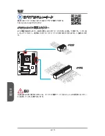
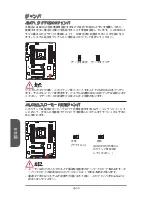
SATA_EX1: SATA Expressコネクター 

SATA Expressは新たな高性能のストレージインターフェースであり、1基のSATA 

Expressデバイスの接続を最大10 Gb/sまでの転送速度をサポートします。SATA 

ExpressケーブルでSATA Expressデバイスをこの3-in-1コネクターに接続します。

B

A

T

1

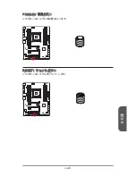
M2_1: M.2ポート

M.2ポートはM.2 SATA 6Gb/sモジュールあるいはM.2 PCIeモジュールのいずれかを

サポートします。

B

A

T

1

 ビデオデモンストレーション

M.2モジュールの取り付け方法をビデオで確認できます。

http://youtu.be/JCTFABytrYA

 注意

• 

M.2 ポートにM.2 SATAインターフェースモジュールを取り付けると、 SATA 

Expressポートまたは5~6ポートが無効になります。

• 

Intel RSTはレガシーROM付きのPCIe M.2 SSDをサポートしません。

• 

M.2 PCIeインターフェースはRAID 0、RAID1、RAID 5とRAID 10をサポートしま

せん。

• 

M.2デバイスの脱着の際には、必ず電源をオフにし、電源ケーブルを抜いてから行

ってください。

Summary of Contents for X99A GAMING 7

Page 1: ...X99A GAMING 7 Motherboard G52 78851XM Preface...

Page 2: ...tel is registered trademarks of Intel Corporation Windows is registered trademarks of Microsoft Corporation AMI is registered trademark of American Megatrends Inc Award is a registered trademark of Ph...

Page 3: ...als within minutes Better yet the power calculator provides accurate estimates of power unit capacity for DIY users Technical Support If a problem arises with your system and no solution can be obtain...

Page 4: ...Do not place anything over the power cord Always Unplug the Power Cord before inserting any add on card or module All cautions and warnings on the equipment should be noted Never pour any liquid into...

Page 5: ...which can be determined by turning the equipment off and on the user is encouraged to try to correct the interference by one or more of the measures listed below Reorient or relocate the receiving ant...

Page 6: ...ent and its antenna must not be co located or operating in conjunction with any other antenna or transmitter European Community Compliance Statement The equipment complies with the RF Exposure Require...

Page 7: ...ld not be disposed of as unsorted household waste Please use the public collection system to return recycle or treat them in compliance with the local regulations Battery Information Chemical Substanc...

Page 8: ...ronik Altger te nicht mehr als kommunale Abf lle entsorgt werden MSI hat europaweit verschiedene Sammel und Recyclingunternehmen beauftragt die in die Europ ische Union in Verkehr gebrachten Produkte...

Page 9: ...de producten die de merknaam MSI dragen en verkocht zijn in de EU Deze goederen kunnen geretourneerd worden op lokale inzamelingspunten SRPSKI Da bi za titili prirodnu sredinu i kao preduze e koje vo...

Page 10: ...h sb rn ch MAGYAR Annak rdek ben hogy k rnyezet nket megv dj k illetve k rnyezetv d k nt fell pve az MSI eml kezteti nt hogy Az Eur pai Uni EU 2005 augusztus 13 n hat lyba l p az elektromos s elektron...

Page 11: ...mium polybrominated biphenyls or polybrominated diphenyl ethers in concentrations exceeding 0 1 weight and 0 01 weight for cadmium except for the exemptions set in Schedule 2 of the Rule T rkiye EEE y...

Page 12: ...tral Processing Unit En 10 Memory En 14 Mounting Screw Holes En 17 Power Supply En 18 Expansion Slots En 19 Internal Connectors En 20 Buttons En 28 Jumper En 30 Switch En 31 LED Status Indicators En 3...

Page 13: ...Jp 2 Jp 5 Jp 6 I O Jp 8 CPU Jp 10 Jp 14 Jp 17 Jp 18 Jp 19 Jp 20 Jp 28 Jp 30 Jp 31 LED Jp 33 Jp 35 BIOS Jp 36 Tc 1 Tc 2 Tc 5 Tc 6 Tc 7 Tc 8 CPU Tc 10 Tc 14 Tc 17 Tc 18 Tc 19 Tc 20 Tc 28 Tc 30 Tc 31 LE...

Page 14: ...10 Sc 14 Sc 17 Sc 18 Sc 19 Sc 20 Sc 28 Sc 30 Sc 31 LED Sc 33 Sc 35 BIOS Sc 36 Installation A 1 CPU A 2 Memory A 4 Motherboard A 5 Power Connector A 7 SATA HDD A 9 M 2 KILLER A 10 Front Panel Connecto...

Page 15: ...motherboard The X99A GAMING 7 Series motherboards are based on Intel X99 chipset for optimal system efficiency Designed to fit the advanced Intel LGA2011 3 processor the X99A GAMING 7 Series motherboa...

Page 16: ...only support IDE mode and AHCI mode Supports Intel Smart Response Technology Windows 7 8 8 1 1x SATA Express port 1x M 2 port supports up to 32Gb s speed M 2 port supports 4 2cm 6cm 8cm length module...

Page 17: ...io connector 2x System panel connectors 1x TPM module connector 1x Chassis Intrusion connector 1x Clear CMOS jumper 1x Power button 1x Reset button 1x OC Genie button 1x Multi BIOS switch 1x Audio pow...

Page 18: ...Split Gamecaster Sound Blaster Cinema2 Intel Extreme Tuning Utility Norton Internet Security Solution Form Factor ATX Form Factor 12 in x 9 6 in 30 5 cm x 24 4 cm For the latest information about CPU...

Page 19: ...us PCI Express Bus PCI Express Bus PS 2 Mouse Keyboard Killer E2205 Gigabit LAN DMI 2 0 PCI Express 3 0 PCI Express 3 0 PCI Express 3 0 PCI Express 3 0 PCI Express Bus Switch X99 PCH Haswell E Process...

Page 20: ...PCI_E5 JPWR1 JUSB2 SATA1_2 SATA3_4 SATA5 JPWR2 CPU Back Panel JUSB1 M2_1 JTPM1 DIMM1 DIMM2 DIMM3 DIMM4 CPUFAN2 SYSFAN3 JSLOW1 OC1 POWER1 RESET1 SATA9_10 JCI1 JFP1 JFP2 BIOS1 JUSB3 JUSB4 SYSFAN2 SYSFA...

Page 21: ...nnector En 26 JBAT1 Clear CMOS Jumper En 30 JCI1 Chassis Intrusion Connector En 25 JFP1 JFP2 System Panel Connectors En 23 JPWR1 2 ATX Power Connectors En 18 JSLOW1 Slow Mode Booting Jumper En 30 JTPM...

Page 22: ...0 devices such as keyboard mouse or other USB 2 0 compatible devices USB 3 0 Port USB 3 0 port is backward compatible with USB 2 0 devices It supports data transfer rate up to 5 Gbit s SuperSpeed USB...

Page 23: ...s Digital Interconnect Format connector is provided for digital audio transmission to external speakers through an optical fiber cable Audio Ports These connectors are used for audio devices Line In S...

Page 24: ...o ensure the safety of the CPU Overclocking This motherboard is designed to support overclocking Before attempting to overclock please make sure that all other system components can tolerate overclock...

Page 25: ...other end 2 Open active lever Active lever Hinge lever Interlock CPU Heatsink Installation When installing a CPU always remember to install a CPU heatsink A CPU heatsink is necessary to prevent overhe...

Page 26: ...rm motion and latch to the socket 5 Line up the CPU to fit the CPU socket Be sure to hold the CPU by the base with the metal contacts facing downward The alignment keys on the CPU will line up with th...

Page 27: ...ocate the CPU fan connector on the motherboard 11 Place the heatsink on the motherboard with the fan s wires facing towards the fan connector and the screws matching the holes on the socket 12 Using a...

Page 28: ...s channels simultaneously to enhance system performance Please refer the following tables for more details Defined Channel list Channel DIMM Slot Channel A DIMM1 DIMM2 Channel B DIMM3 DIMM4 Channel C...

Page 29: ...am DIMM1 DIMM5 DIMM1 DIMM2 DIMM3 DIMM4 DIMM8 DIMM7 DIMM6 DIMM5 Triple Channel mode Installed DIMMs 3 memory modules Diagram DIMM1 DIMM3 DIMM5 DIMM1 DIMM2 DIMM3 DIMM4 DIMM8 DIMM7 DIMM6 DIMM5 Quad Chann...

Page 30: ...6 DIMM5 Installed DIMMs 8 memory modules Diagram DIMM1 DIMM2 DIMM3 DIMM4 DIMM5 DIMM6 DIMM7 DIMM8 DIMM1 DIMM2 DIMM3 DIMM4 DIMM8 DIMM7 DIMM6 DIMM5 Important To ensure system stability for Dual Triple Qu...

Page 31: ...therboard with the screws provided with your computer case The locations of the screw holes on the motherboard are shown below For more information please refer to the manual that came with the comput...

Page 32: ...power cable should be hooked on the motherboard s power connector BAT1 1 3 3 3 V 1 3 3 V 1 4 1 2 V 2 3 3 V 1 5 G r o u n d 3 G r o u n d 1 6 P S O N 4 5 V 1 7 G r o u n d 5 G r o u n d 1 8 G r o u n...

Page 33: ...x16 3 0 x16 3 0 x8 PCI_E3 3 0 x16 3 0 x8 3 0 x16 3 0 x8 PCI_E5 3 0 x8 PCI_E6 3 0 x8 M 2 3 0 x4 3 0 x4 3 0 x4 3 0 x4 2 0 x2 3 0 x4 SATA Express 2 0 x2 2 0 x2 2 0 x2 2 0 x2 2 0 x2 2 0 x2 When installin...

Page 34: ...nterface module in the M 2 port SATA7 10 do not support RAID mode Many SATA devices also need a power cable from the power supply Such devices include disk drives HDD solid state drives SSD and optica...

Page 35: ...ATA 6Gb s module or M 2 PCIe module BAT1 Video Demonstration Watch the video to learn how to install M 2 module http youtu be JCTFABytrYA Important The SATA Express port or SATA5 6 ports will be unava...

Page 36: ...1 G r o u n d 2 S p e e d C o n t r o l 3 S e n s e 4 N C 1 G r o u n d 2 1 2 V 3 S e n s e 4 S p e e d C o n t r o l BAT1 CPUFAN1 CPUFAN2 SYSFAN1 SYSFAN2 SYSFAN3 Important Please refer to your proce...

Page 37: ...atch the video to learn how to Install front panel connectors http youtu be DPELIdVNZUI BAT1 1 3 1 0 N o P i n 5 R e s e t S w i t c h H D D L E D P o w e r S w i t c h P o w e r L E D 7 9 R e s e r v...

Page 38: ...tor will convert data channels to extra power channels to quickly charge your connected device Please note that when the Super Charger application is turned on data transmission and synchronization ov...

Page 39: ...G r o u n d 9 N o P i n Important Note that the VCC and GND pins must be connected correctly to avoid possible damage JCI1 Chassis Intrusion Connector This connector connects to the chassis intrusion...

Page 40: ...e a d P h o n e L 8 N o P i n 6 M I C D e t e c t i o n 4 N C 2 G r o u n d AUDPWR1 Direct Audio Power Connector This connector is used to provide direct power to back panel audio ports The direct aud...

Page 41: ...ils and usages BAT1 1 0 N o P i n 1 4 G r o u n d 8 5 V P o w e r 1 2 G r o u n d 6 S e r i a l I R Q 4 3 3 V P o w e r 2 3 V S t a n d b y p o w e r 1 L P C C l o c k 3 L P C R e s e t 5 L P C a d d...

Page 42: ...nie button http youtu be nIpRvWkUazg BAT1 OC GENIE OC GENIE On Off Important This motherboard provides two ways to enable OC Genie press the physical OC Genie button on the motherboard or click the vi...

Page 43: ...n This button is used to turn on and turn off the system Press the button once to turn on or turn off the system BAT1 RESET1 Reset Button This reset button is used to reset the system Press the button...

Page 44: ...while the system is off Afterwards open the jumper Do not clear the CMOS RAM while the system is on because it will damage the motherboard JSLOW1 Slow Mode Booting Jumper This jumper is used for LN2 c...

Page 45: ...atest BIOS file from the MSI official website at www msi com and then decompress the file 3 Copy the AFUDE238 exe and the BIOS file to the bootable USB flash drive BIOS recovery steps 1 Power off the...

Page 46: ...ports Direct Power mode Onboard Power mode Default BAT1 Important Before switching to Direct Power mode please make sure the Direct Audio Power Connector AUDPWR1 has been connected to the power suppl...

Page 47: ...rs BAT1 BIOS B LED Debug LED BIOS A LED LED Status Table The following table describes the status of LED indicators LED LED Status Description BIOS B Green BIOS B in operation BIOS A Blue BIOS A in op...

Page 48: ...lization 19 1C 3B 3E Early South Bridge Initialization 1D 2F 31 3F 4E 50 55 Early Memory Initialization 63 67 D0 Late CPU Initialization 69 6F D1 Late North Bridge Initialization 70 77 D2 Late South B...

Page 49: ...ram The bundle also includes a variety of powerful and creative utilities Driver Utilities Installation Please follow the steps below to install drivers and utilities for your new computer 1 Insert MS...

Page 50: ...he message disappears before you respond and you still need to enter BIOS restart the system by turning the computer OFF then back ON or pressing the RESET button You may also restart the system by si...

Page 51: ...ipset and boot devices OC This menu contains the frequency and voltage adjustments Increasing the frequency can get better performance however high frequency and heat can cause instability we do not r...

Page 52: ...evice priority bar You can move the device icons to change the boot priority High priority Low priority System information Shows the time date CPU name CPU frequency DRAM frequency DRAM capacity and t...

Page 53: ...Select Icon Field Esc Click the right button Jump to the Exit menu or return to the previous from a submenu Increase the numeric value or make changes Decrease the numeric value or make changes F1 Ge...

Page 54: ...re in BIOS setup Note We use as the symbol for the OC settings of Advanced mode CPU Setting CPU Ratio Apply Mode All Core Sets the applying mode for adjusted CPU ratio This item only appears when a CP...

Page 55: ...U cores to boost CPU performance This item appears when the installed CPU supports this function Auto This setting will be configured automatically by BIOS Enabled All CPU cores would be increased to...

Page 56: ...t X M P technology Disabled Disables this function Profile 1 Uses profile1 over clocking settings of installed XMP memory module Profile 2 Uses profile2 over clocking settings of installed XMP memory...

Page 57: ...ffective power saving capability Optimized Sets the optimum power phase profile for CPU it could provide the system with an optimum power saving capability Disabled Disables the PWM power phase switch...

Page 58: ...this setting automatically Higher voltage provides less protection and may damage the system DRAM CH_A B CH_C D Over Current Protection Auto Sets the current limit for DRAM over current protection Au...

Page 59: ...fset the voltage by positive value mode Allows you to offset the voltage by negative value mode CPU Core Ring Voltage Offset Auto Sets the offset value for CPU Core Ring voltage If set to Auto BIOS wi...

Page 60: ...by pressing F5 DIMMX Memory SPD Press Enter to enter the sub menu The sub menu displays the information of installed memory Read only CPU Features Press Enter to enter the sub menu Hyper Threading Ena...

Page 61: ...le systems virtually Disabled Disables this function Hardware Prefetcher Enabled Enables or disables the hardware prefetcher MLC Streamer prefetcher Enabled Allows the hardware prefetcher to automatic...

Page 62: ...p Technology This item will appear when Simple Advanced Mode is set to Simple Enabled Enables the EIST to adjust CPU voltage and core frequency dynamically It can decrease average power consumption an...

Page 63: ...rotection Disabled Disables this function for overclocking Internal VR Efficiency Management Auto Enables or disables the CPU internal VR efficiency management Auto This setting will be configured aut...

Page 64: ......

Page 65: ...X99A GAMING 7 MS 7885 v3 X ATX X99A GAMING 7 Intel X99 Intel LGA2011 3 X99A GAMING 7...

Page 66: ...Technology 3 Way NVIDIA SLI Technology Windows 7 Windows 8 8 1 Intel X99 SATA 6Gb s 10 SATA 2 SATA1 6 RAID 0 RAID 1 RAID 5 RAID 10 SATA7 10 IDE AHCI Intel Smart Response Technology Windows 7 8 8 1 SAT...

Page 67: ...CPU 2 4 3 1 2 TPM 1 1 CMOS 1 1 1 OC Genie 1 BIOS 1 1 1 2 Digit LED 1 I O NUVOTON NCT6792 CPU CPU CPU BIOS 128 Mb 2 UEFI AMI BIOS ACPI 5 0 PnP 1 0a SM BIOS 2 7 DMI 2 0 Audio Boost 2 Military Class 4 OC...

Page 68: ...s Super Charger Fast Boot MSI Gaming APP ECO Center XSplit Gamecaster Sound Blaster Cinema2 Intel Extreme Tuning Utility Norton Internet Security Solution ATX 12 in x 9 6 in 30 5 cm x 24 4 cm CPU http...

Page 69: ...e Keyboard Killer E2205 Gigabit LAN DMI 2 0 PCI Express 3 0 PCI Express 3 0 PCI Express 3 0 PCI Express 3 0 PCI Express Bus Switch X99 PCH Haswell E Processor LGA2011 3 CPU NV6792 Super I O Realtek AL...

Page 70: ...PWR1 JUSB2 SATA1_2 SATA3_4 SATA5 JPWR2 CPU JUSB1 M2_1 JTPM1 DIMM1 DIMM2 DIMM3 DIMM4 CPUFAN2 SYSFAN3 JSLOW1 OC1 POWER1 RESET1 SATA9_10 JCI1 JFP1 JFP2 BIOS1 JUSB3 JUSB4 SYSFAN2 SYSFAN1 JAUD1 JBAT1 DIMM8...

Page 71: ...3 CPU Kr 11 DIMM1 8 Kr 14 JAUD1 Kr 26 JBAT1 CMOS Kr 30 JCI1 Kr 25 JFP1 JFP2 Kr 23 JPWR1 2 ATX Kr 18 JSLOW1 Kr 30 JTPM1 TPM Kr 27 JUSB1 2 USB 3 0 Kr 24 JUSB3 4 USB 2 0 Kr 25 M2_1 M 2 Kr 21 OC1 OC Geni...

Page 72: ...OS a USB 2 0 USB 2 0 USB 2 0 USB 2 0 USB 3 0 USB 3 0 USB 2 0 5 Gbit s superspeed USB 3 1 USB 3 1 USB 3 0 2 0 10 Gb s superspeed 10 Gbp s USB 3 0 3 1 USB 3 0 3 1 USB USB 3 0 3 1 S PDIF SS RS CS USB 3...

Page 73: ...AN LAN Local Area Network LINK ACT LED SPEED LED LED LED Link Activity LED LED LAN LAN LAN Speed LED LED 10 Mbps 100 Mbps 1 Gbps S PDIF S PDIF Sony Philips Digital Interconnect Format SS SS 7 1 RS 4 5...

Page 74: ...Kr 10 CPU CPU CPU CPU CPU CPU CPU LGA2011 3 CPU CPU LGA2011 3 CPU 4 1 1...

Page 75: ...Kr 11 3 4 1 2 CPU CPU CPU CPU CPU CPU CPU http youtu be WPhyn2C5mgs...

Page 76: ...Kr 12 7 8 5 CPU CPU 6...

Page 77: ...Kr 13 9 CPU CPU 10 CPU 11 12 4 9 inch pounds 13 CPU CPU BAT1 CPUFAN1...

Page 78: ...BAT1 DIMM1 DIMM2 DIMM3 DIMM4 DIMM8 DIMM7 DIMM6 DIMM5 http youtu be T03aDrJPyQs 4 2 DIMM 4 DIMM A DIMM1 DIMM2 B DIMM3 DIMM4 C DIMM5 DIMM6 D DIMM7 DIMM8 DDR4 DDR3 DDR4 DDR4 DIMM DDR4 DIMM1 DIMM 16GB 12...

Page 79: ...DIMM1 DIMM5 DIMM1 DIMM2 DIMM3 DIMM4 DIMM8 DIMM7 DIMM6 DIMM5 DIMMs 3 DIMM1 DIMM3 DIMM5 DIMM1 DIMM2 DIMM3 DIMM4 DIMM8 DIMM7 DIMM6 DIMM5 DIMMs 4 DIMM1 DIMM3 DIMM5 DIMM7 DIMM1 DIMM2 DIMM3 DIMM4 DIMM8 DIM...

Page 80: ...16 DIMMs 6 DIMM1 DIMM2 DIMM3 DIMM5 DIMM6 DIMM7 DIMM1 DIMM2 DIMM3 DIMM4 DIMM8 DIMM7 DIMM6 DIMM5 DIMMs 8 DIMM1 DIMM2 DIMM3 DIMM4 DIMM5 DIMM6 DIMM7 DIMM8 DIMM1 DIMM2 DIMM3 DIMM4 DIMM8 DIMM7 DIMM6 DIMM5 D...

Page 81: ...Kr 17 I O I O I O I O I O BAT1...

Page 82: ...o u n d 1 6 P S O N 4 5 V 1 7 G r o u n d 5 G r o u n d 1 8 G r o u n d 6 5 V 1 9 G r o u n d 7 G r o u n d 2 2 5 V 1 0 1 2 V 2 0 R e s 8 P W R O K 2 3 5 V 1 1 1 2 V 2 1 5 V 9 5 V S B 2 4 G r o u n d...

Page 83: ...nes 1 Way 2 Way 3 Way CPU 40 28 40 28 40 28 PCI_E1 3 0 x16 3 0 x16 3 0 x16 3 0 x16 3 0 x16 3 0 x8 PCI_E3 3 0 x16 3 0 x8 3 0 x16 3 0 x8 PCI_E5 3 0 x8 PCI_E6 3 0 x8 M 2 3 0 x4 3 0 x4 3 0 x4 3 0 x4 2 0 x...

Page 84: ...VD SATA HDD http youtu be RZsMpqxythc SATA2 SATA1 SATA5 SATA4 SATA3 SATA8 SATA7 SATA10 SATA9 SATA6 SATA1 6 RAID 0 RAID 1 RAID 5 RAID 10 SATA7 10 IDE AHCI BAT1 M 2 SATA M 2 SATA5 SATA6 SATA7 10 RAID HD...

Page 85: ...SATA SATA 10 Gb s SATA SATA SATA 3 in 1 BAT1 M2_1 M 2 M 2 M 2 SATA 6Gb s M 2 PCIe BAT1 M 2 http youtu be JCTFABytrYA M 2 M 2 SATA SATA SATA5 6 Intel RST ROM PCIe M 2 SSD M 2 PCIe RAID 0 RAID1 RAID 5...

Page 86: ...FAN1 2 SYSFAN1 3 12V CPU 1 G r o u n d 2 S p e e d C o n t r o l 3 S e n s e 4 N C 1 G r o u n d 2 1 2 V 3 S e n s e 4 S p e e d C o n t r o l BAT1 CPUFAN1 CPUFAN2 SYSFAN1 SYSFAN2 SYSFAN3 CPU CPU Comm...

Page 87: ...Guide M M M http youtu be DPELIdVNZUI BAT1 1 3 1 0 N o P i n 5 R e s e t S w i t c h H D D L E D P o w e r S w i t c h P o w e r L E D 7 9 R e s e r v e d 8 6 4 2 JFP1 1 G r o u n d 3 S u s p e n d L...

Page 88: ...X _ C _ D P 2 0 N o P i n 1 9 P o w e r 1 8 U S B 3 _ R X _ D N 1 7 U S B 3 _ R X _ D P 1 6 G r o u n d 1 5 U S B 3 _ T X _ C _ D N 1 4 U S B 3 _ T X _ C _ D P 1 3 G r o u n d 1 2 U S B 2 0 1 1 U S B...

Page 89: ...Kr 25 JUSB3 4 USB 2 0 USB HDD MP3 USB BAT1 1 0 N C 8 G r o u n d 6 U S B 1 4 U S B 1 2 V C C 1 V C C 3 U S B 0 5 U S B 0 7 G r o u n d 9 N o P i n VCC GND JCI1 BIOS BAT1 2 C I N T R U 1 G r o u n d...

Page 90: ...M I C L 3 M I C R 1 0 H e a d P h o n e D e t e c t i o n 5 H e a d P h o n e R 7 S E N S E _ S E N D 9 H e a d P h o n e L 8 N o P i n 6 M I C D e t e c t i o n 4 N C 2 G r o u n d AUDPWR1 BAT1 1 G...

Page 91: ...r 1 2 G r o u n d 6 S e r i a l I R Q 4 3 3 V P o w e r 2 3 V S t a n d b y p o w e r 1 L P C C l o c k 3 L P C R e s e t 5 L P C a d d r e s s d a t a p i n 0 7 L P C a d d r e s s d a t a p i n 1 9...

Page 92: ...OC Genie OC Genie OC Genie CPU OC Genie http youtu be nIpRvWkUazg BAT1 OC GENIE OC GENIE OC Genie OC Genie BIOS OC Genie BIOS OC Genie Function Control OC Genie OC Genie DDR4 2133 OC Genie BIOS OC Gen...

Page 93: ...Kr 29 POWER1 BAT1 RESET1 BAT1 Reset...

Page 94: ...Kr 30 JBAT1 CMOS CMOS RAM CMOS RAM OS CMOS RAM BAT1 CMOS RAM CMOS RAM JSLOW1 LN2 BAT1 BIOS POST CPU...

Page 95: ...S ROM Labeled A B BIOS ROM A B A LED LED BAT1 AFUDOS BIOS BIOS BIOS 1 USB 2 MSI www msi com BIOS 3 USB AFUDE238 exe BIOS BIOS 1 2 BIOS BIOS ROM 3 USB USB 4 USB 5 BIOS failed BIOS ROM 6 BIOS AFUDE238 E...

Page 96: ...Kr 32 AUD_SW1 BAT1 Direct Power mode Direct Audio Power Connector AUDPWR1...

Page 97: ...Kr 33 LED BAT1 BIOS B LED Debug LED BIOS A LED LED LED LED LED BIOS B BIOS B BIOS A BIOS A MSI LED MSI LED...

Page 98: ...e LED LED 02 07 CPU 03 08 04 09 0B 11 14 32 36 56 5A CPU 15 18 37 3A 19 1C 3B 3E 1D 2F 31 3F 4E 50 55 63 67 D0 CPU 69 6F D1 70 77 D2 92 96 B5 D4 PCI 97 98 99 B2 D5 D7 ROM VGA RAID 9A A7 B4 USB SATA SC...

Page 99: ...Kr 35 MSI 1 MSI OS 2 3 4 5 OK 6...

Page 100: ...BIOS CPU CPU DRAM OS BIOS POST Power On Self Test DEL Press Del to run BIOS setup or F11 to run boot menu DEL BIOS F11 BIOS RESET Ctrl Alt Delete MSI BIOS MSI Fast Boot GO2BIOS GO2BIOS BIOS MSI Fast...

Page 101: ...Kr 37 BIOS BIOS BIOS Virtual OC Genie BIOS SETTINGS OC M FLASH USB BIOS OC PROFILE HARDWARE MONITOR BOARD EXPLORER...

Page 102: ...Kr 38 Virtual OC Genie OC Genie MSI OC Genie OC BIOS CPU CPU DRAM DRAM BIOS BIOS BIOS BIOS Default HomePage BIOS OC BIOS Favorite1 5 BIOS...

Page 103: ...Kr 39 BIOS Enter Esc F1 F2 F3 F4 CPU F5 Memory Z F6 F8 OC Profile F9 OC Profile F10 F12 FAT FAT32 USB...

Page 104: ...Simple OC Simple OC Advanced OC BIOS OC CPU CPU Ratio Apply Mode All Core CPU Turbo Boost CPU All Core CPU Ratio CPU Adjust CPU Ratio Per Core X Core Ratio Limit X Core Ratio Limit CPU CPU Ratio Auto...

Page 105: ...d CPU Disabled Intel Turbo Boost Enabled Intel Turbo Boost CPU Enabled CPU Disabled Enhanced Turbo Auto CPU Enhanced Turbo CPU Auto BIOS Enabled CPU Disabled OC Genie Function Control By Onboard Butto...

Page 106: ...DRAM Frequency Auto DRAM Adjusted DRAM Frequency DRAM Extreme Memory Profile X M P Disabled XMP Extreme Memory Profile XMP Disabled Profile 1 XMP 1 Profile 2 XMP 2 Memory Try It Disabled Memory Try It...

Page 107: ...e Control Auto CPU PWM Auto BIOS CPU PWM Auto BIOS Normal CPU Optimized CPU Disabled PWM CPU Vdroop Offset Control Auto CPU vdroop Auto BIOS CPU Over Voltage Protection Auto CPU Auto BIOS CPU Under Vo...

Page 108: ..._C D Under Voltage Protection Auto DRAM Auto BIOS DRAM CH_A B CH_C D Over Current Protection Auto DRAM Auto BIOS Enhanced DRAM CH_A B CH_C D Switching Frequency Auto PWM DRAM Auto BIOS DRAM CH_A B CH_...

Page 109: ...ore Ring CPU Core Ring Offset Mode Adaptive Offset Override Offset Auto BIOS positive value negative value CPU Core Ring Voltage Offset Auto CPU Core Ring Auto BIOS CPU Core Ring Offset Mode Adaptive...

Page 110: ...Support Enter CPU MEMORY Z Enter F5 DIMM X Memory SPD Enter CPU Features Enter Hyper Threading Enabled Hyper Threading CPU Enable Intel Hyper Threading Disabled HT Active Processor Cores Control Disa...

Page 111: ...tualization for Direct I O Enabled Disabled Hardware Prefetcher Enabled MLC Streamer prefetcher Enabled L2 CPU Disabled Adjacent Cache Line Prefetch Enabled CPU MLC Spatial prefetcher Enabled Disabled...

Page 112: ...C State Auto BIOS C0 C6 C6 C2 C0 EIST Enabled Enhanced Intel SpeedStep Technology Simple Advanced Mode Simple Enabled CPU Disabled Intel Turbo Boost Enabled Intel Turbo Boost CPU Enabled CPU Disabled...

Page 113: ...ection Auto CPU VR Voltage Regulator Auto BIOS Enabled CPU VR Disabled Internal VR Efficiency Management Auto Auto BIOS Enabled Disabled DMI Gen 2 Enabled DMI Direct Media Interface GEN 2 DMI De empha...

Page 114: ......

Page 115: ...X99A GAMING 7 Series MS 7885 v3 X ATX X99A GAMING 7 X99 LGA2011 3...

Page 116: ...LI Windows 7 Windows 8 8 1 X99 Express SATA 6Gb s x10 SATA Express 2 SATA1 6 RAID 0 RAID1 RAID 5 RAID 10 SATA7 10 IDE AHCI Intel Smart Response Technology Windows 7 8 8 1 SATA Express x1 M 2 x1 32Gb s...

Page 117: ...PU x2 4 x3 x1 x2 TPM x1 x1 CMOS x1 x1 x1 OC Genie x1 BIOS x1 x1 x1 2 Digit Debug Code LED x1 I O NUVOTON NCT6792 CPU CPU CPU BIOS 2x 128 Mb UEFI AMI BIOS ACPI 5 0 PnP 1 0a SM BIOS 2 7 DMI 2 0 Audio Bo...

Page 118: ...s Super Charger Fast Boot MSI Gaming APP ECO Center XSplit Gamecaster Sound Blaster Cinema2 Intel Extreme Tuning Norton Internet Security Solution ATX 12 in x 9 6 in 30 5 cm x 24 4 cm CPU Web http www...

Page 119: ...e Keyboard Killer E2205 Gigabit LAN DMI 2 0 PCI Express 3 0 PCI Express 3 0 PCI Express 3 0 PCI Express 3 0 PCI Express Bus Switch X99 PCH Haswell E Processor LGA2011 3 CPU NV6792 Super I O Realtek AL...

Page 120: ...R1 JUSB2 SATA1_2 SATA3_4 SATA5 JPWR2 CPU I O JUSB1 M2_1 JTPM1 DIMM1 DIMM2 DIMM3 DIMM4 CPUFAN2 SYSFAN3 JSLOW1 OC1 POWER1 RESET1 SATA9_10 JCI1 JFP1 JFP2 BIOS1 JUSB3 JUSB4 SYSFAN2 SYSFAN1 JAUD1 JBAT1 DIM...

Page 121: ...CPU Socket Jp 11 DIMM1 8 Jp 14 JAUD1 Jp 26 JBAT1 CMOS Jp 30 JCI1 Jp 25 JFP1 JFP2 Jp 23 JPWR1 2 ATX Jp 18 JSLOW1 Jp 30 JTPM1 TPM Jp 27 JUSB1 2 USB 3 0 Jp 24 JUSB3 4 USB 2 0 Jp 25 M2_1 M 2 Jp 21 OC1 OC...

Page 122: ...MOS OS USB 2 0 USB 2 0 USB 3 0 USB 3 0 USB 2 0 5 Gbit s USB 3 1 USB 3 1 USB 3 0 2 0 10 Gbit s USB 10 Gbps USB 3 0 3 1 USB 3 0 3 1 USB 3 0 3 1 S PDIF Line In SS Out Line Out RS Out CS Out USB 3 0 CMOS...

Page 123: ...D SPEED LED LED LED Link Activity LED LED Off Speed LED LED Off 10 Mbpss 100 Mbpss 1 Gbpss S PDIF S PDIF Sony Philips Digital Interconnect Format Line In SS Out Line In SS Out 7 1 Line out Mic RS Out...

Page 124: ...Jp 10 CPU CPU CPU CPU CPU CPU CPU ATX CPU CPU LGA2011 3 CPU CPU LGA2011 3 CPU 2 1 1...

Page 125: ...Jp 11 3 4 1 2 CPU CPU CPU CPU CPU CPU CPU http youtu be WPhyn2C5mgs...

Page 126: ...Jp 12 7 8 5 CPU CPU CPU CPU 6...

Page 127: ...Jp 13 9 CPU CPU 10 CPU 11 12 9 13 CPU BAT1 CPUFAN1...

Page 128: ...4 DIMM BAT1 DIMM1 DIMM2 DIMM3 DIMM4 DIMM8 DIMM7 DIMM6 DIMM5 http youtu be T03aDrJPyQs 4 DIMM 2 4 DIMM A DIMM1 DIMM2 B DIMM3 DIMM4 C DIMM5 DIMM6 D DIMM7 DIMM8 DDR4 DDR3 DDR4 DDR4 DDR3 DIMM1 DIMM 16GB 1...

Page 129: ...DIMM1 DIMM5 DIMM1 DIMM2 DIMM3 DIMM4 DIMM8 DIMM7 DIMM6 DIMM5 DIMM 3 DIMM1 DIMM3 DIMM5 DIMM1 DIMM2 DIMM3 DIMM4 DIMM8 DIMM7 DIMM6 DIMM5 DIMM 4 DIMM1 DIMM3 DIMM5 DIMM7 DIMM1 DIMM2 DIMM3 DIMM4 DIMM8 DIMM7...

Page 130: ...16 DIMM 6 DIMM1 DIMM2 DIMM3 DIMM5 DIMM6 DIMM7 DIMM1 DIMM2 DIMM3 DIMM4 DIMM8 DIMM7 DIMM6 DIMM5 DIMM 8 DIMM1 DIMM2 DIMM3 DIMM4 DIMM5 DIMM6 DIMM7 DIMM8 DIMM1 DIMM2 DIMM3 DIMM4 DIMM8 DIMM7 DIMM6 DIMM5 DI...

Page 131: ...Jp 17 I O I O I O I O I O BAT1...

Page 132: ...u n d 1 6 P S O N 4 5 V 1 7 G r o u n d 5 G r o u n d 1 8 G r o u n d 6 5 V 1 9 G r o u n d 7 G r o u n d 2 2 5 V 1 0 1 2 V 2 0 R e s 8 P W R O K 2 3 5 V 1 1 1 2 V 2 1 5 V 9 5 V S B 2 4 G r o u n d 1...

Page 133: ...3 Way CPU 40 28 40 28 40 28 PCI_E1 3 0 x16 3 0 x16 3 0 x16 3 0 x16 3 0 x16 3 0 x8 PCI_E3 3 0 x16 3 0 x8 3 0 x16 3 0 x8 PCI_E5 3 0 x8 PCI_E6 3 0 x8 M 2 3 0 x4 3 0 x4 3 0 x4 3 0 x4 2 0 x2 3 0 x4 SATA Ex...

Page 134: ...ay SATA HDD http youtu be RZsMpqxythc SATA2 SATA1 SATA5 SATA4 SATA3 SATA8 SATA7 SATA10 SATA9 SATA6 SATA1 6 RAID 0 RAID 1 RAID 5 RAID 10 SATA7 10 IDE AHCI BAT1 M 2 M 2 SATA SATA5 SATA6 SATA7 10 RAID SA...

Page 135: ...press 1 SATA Express 10 Gb s SATA Express SATA Express 3 in 1 BAT1 M2_1 M 2 M 2 M 2 SATA 6Gb s M 2 PCIe BAT1 M 2 http youtu be JCTFABytrYA M 2 M 2 SATA SATA Express 5 6 Intel RST ROM PCIe M 2 SSD M 2...

Page 136: ...FAN1 2 SYSFAN1 3 12V CPU 1 G r o u n d 2 S p e e d C o n t r o l 3 S e n s e 4 N C 1 G r o u n d 2 1 2 V 3 S e n s e 4 S p e e d C o n t r o l BAT1 CPUFAN1 CPUFAN2 SYSFAN1 SYSFAN2 SYSFAN3 CPU Command...

Page 137: ...tu be DPELIdVNZUI BAT1 1 3 1 0 N o P i n 5 R e s e t S w i t c h H D D L E D P o w e r S w i t c h P o w e r L E D 7 9 R e s e r v e d 8 6 4 2 JFP1 1 G r o u n d 3 S u s p e n d L E D 5 P o w e r L E...

Page 138: ...d 6 U S B 3 _ T X _ C _ D P 2 0 N o P i n 1 9 P o w e r 1 8 U S B 3 _ R X _ D N 1 7 U S B 3 _ R X _ D P 1 6 G r o u n d 1 5 U S B 3 _ T X _ C _ D N 1 4 U S B 3 _ T X _ C _ D P 1 3 G r o u n d 1 2 U S...

Page 139: ...Jp 25 JUSB3 4 USB 2 0 USB USB HDD MP3 BAT1 1 0 N C 8 G r o u n d 6 U S B 1 4 U S B 1 2 V C C 1 V C C 3 U S B 0 5 U S B 0 7 G r o u n d 9 N o P i n VCC GND JCI1 2 BIOS BAT1 2 C I N T R U 1 G r o u n d...

Page 140: ...e a d P h o n e D e t e c t i o n 5 H e a d P h o n e R 7 S E N S E _ S E N D 9 H e a d P h o n e L 8 N o P i n 6 M I C D e t e c t i o n 4 N C 2 G r o u n d AUDPWR1 BAT1 1 G r o u n d 2 1 2 V _ A U...

Page 141: ...r 1 2 G r o u n d 6 S e r i a l I R Q 4 3 3 V P o w e r 2 3 V S t a n d b y p o w e r 1 L P C C l o c k 3 L P C R e s e t 5 L P C a d d r e s s d a t a p i n 0 7 L P C a d d r e s s d a t a p i n 1 9...

Page 142: ...e OC Genie OC Genie http youtu be nIpRvWkUazg BAT1 OC GENIE OC GENIE OC Genie OC Genie BIOS Virtual OC Genie BIOS OC Genie Function Control OC Genie OC Genie DDR4 2133 OC Genie BIOS OC Genie OC Genie...

Page 143: ...Jp 29 POWER1 BAT1 RESET1 BAT1 Reset...

Page 144: ...Jp 30 JBAT1 CMOS BIOS CMOS CMOS OS BAT1 CMOS RAM CMOS JSLOW1 LN2 BAT1 BIOS POST CPU Enabled...

Page 145: ...IOS ROM A B BIOS ROM A ROM B A LED LED BAT1 AFUDOS BIOS BIOS BIOS 1 USB 2 MSI WEB www msi com BIOS 3 AFUDE238 exe BIOS USB BIOS 1 2 BIOS BIOS ROM 3 USB USB 4 USB 5 BIOS BIOS ROM 6 BIOS AFUDE238 EXXXXI...

Page 146: ...Jp 32 AUD_SW1 I O BAT1 AUDPWR1...

Page 147: ...Jp 33 LED BAT1 BIOS B LED Debug LED BIOS A LED LED LED LED LED BIOS B BIOS B BIOS A BIOS BA MSI LED MSI LED...

Page 148: ...D LED 02 07 CPU 03 08 04 09 0B 11 14 32 36 56 5A CPU 15 18 37 3A 19 1C 3B 3E 1D 2F 31 3F 4E 50 55 63 67 D0 CPU 69 6F D1 70 77 D2 92 96 B5 D4 PCI 97 98 99 B2 D5 D7 Option ROM VGA RAID 9A A7 B4 USB SATA...

Page 149: ...Jp 35 OS MSI 1 MSI OS autorun 2 3 Install 4 5 OK 6...

Page 150: ...IOS CPU CPU DRAM OS BIOS BIOS POST Power On Self Test DEL BIOS Press Del to run BIOS setup or F11 to run boot menu DEL F11 DEL RESET Ctrl Alt Delete MSI BIOS 2 MSI Fast Boot GO2BIOS GO2BIOS PC BIOS MS...

Page 151: ...Jp 37 BIOS BIOS BIOS Virtual OC Genie BIOS SETTINGS OC M FLASH USB BIOS OC PROFILE HARDWARE MONITOR BOARD EXPLORER...

Page 152: ...Jp 38 Virtual OC Genie OC Genie OC Genie MSI OC Genie OC BIOS CPU DRAM DRAM BIOS BIOS BIOS BIOS Default HomePage BIOS OC BIOS Favorite1 5 BIOS 1...

Page 153: ...Jp 39 BIOS Enter Esc F1 F2 F3 My Favorites F4 CPU F5 Memory Z F6 Optimized defaults F8 OC F9 OC F10 F12 FAT FAT32 USB...

Page 154: ...e BIOS OC Simple BIOS OC Advanced BIOS OC OC CPU CPU Ratio Apply Mode All Core CPU CPU Turbo Boost All Core CPU Ratio CPU Adjust CPU Ratio CPU Per Core X Core Ratio Limit X Core Ratio Limit CPU CPU Ra...

Page 155: ...urbo Boost Enabled CPU Enabled CPU CPU Disabled Enhanced Turbo Auto CPU Enhanced Turbo CPU Auto BIOS Enabled CPU Disabled OC Genie Function Control By Onboard Button BIOS Virtual OC Genie OC Genie MSI...

Page 156: ...cy Auto DRAM Adjusted DRAM Frequency DRAM Extreme Memory Profile X M P Disabled X M P Extreme Memory Profile X M P Disabled Profile 1 XMP 1 Profile 2 XMP 2 Memory Try It Disabled Memory Try It DRAM Ti...

Page 157: ...ontrol Auto CPU PWM Auto BIOS CPU PWM Auto BIOS Normal CPU Optimized CPU Disabled PWM CPU Vdroop Offset Control Auto CPU vdroop offset Auto BIOS CPU Over Voltage Protection Auto CPU Auto BIOS CPU Unde...

Page 158: ..._C D Under Voltage Protection Auto DRAM Auto BIOS DRAM CH_A B CH_C D Over Current Protection Auto DRAM Auto BIOS Enhanced DRAM CH_A B CH_C D Switching Frequency Auto PWM DRAM Auto BIOS DRAM CH_A B CH_...

Page 159: ...CPU Core Ring CPU Core Ring Voltage Mode Offset Mode Adaptive Offset Override Offset Auto BIOS CPU Core Ring Voltage Offset Auto CPU Core Ring Auto BIOS CPU Core Ring Voltage Mode Offset Mode Adaptiv...

Page 160: ...F4 CPU Technology Support Enter CPU MEMORY Z Enter F5 DIMMX Memory SPD Enter CPU Features Enter Hyper Threading Enabled CPU CPU CPU Enable Disabled HT Active Processor Cores Control Disabled Core0 X C...

Page 161: ...I O Enabled VT D OS Disabled Hardware Prefetcher Enabled MLC Enabled CPU L2 Disabled Adjacent Cache Line Prefetch Enabled CPU MLC Spatial prefetcher Enabled Disabled CPU AES Instructions Enabled CPU...

Page 162: ...state Intel C State Auto BIOS C0 C6 C6 C2 C0 EIST Enabled Enhanced Intel SpeedStep Simple Advanced Mode Simple Enabled EIST CPU Disabled EIST Intel Turbo Boost Enabled Simple CPU Enabled CPU CPU Disa...

Page 163: ...nternal VR OVP OCP Protection Auto CPU VR Auto BIOS Enabled CPU VR Disabled Internal VR Efficiency Management Auto CPU VR Auto BIOS Enabled VR Disabled DMI Gen 2 Enabled DMI 2 DMI De emphasis Control...

Page 164: ......

Page 165: ...X99A GAMING 7 MS 7885 v3 X ATX Intel X99 Intel LGA2011 3 X99A GAMING 7...

Page 166: ...SLI Windows 7 Windows 8 8 1 Intel X99 Express 10 SATA 6Gb s 2 SATA Express SATA1 6 RAID 0 RAID 1 RAID 5 RAID 10 SATA7 10 IDE AHCI Intel Intel Smart Response Technology Windows 7 8 8 1 1 SATA Express 1...

Page 167: ...0 4 USB 2 0 2 USB 3 0 4 USB 3 0 2 4 pin CPU 3 4 pin 1 2 1 TPM 1 1 CMOS 1 1 1 OC Genie 1 BIOS 1 1 Slow mode 1 LED I O NUVOTON NCT6792 CPU CPU CPU BIOS 2x 128 Mb flash UEFI AMI BIOS ACPI 5 0 PnP 1 0a SM...

Page 168: ...6 Smart Utilities Super Charger Fast Boot MSI Gaming APP ECO Center XSplit Gamecaster Intel Extreme Tuning Utility Norton Internet Security Solution ATX 12 x 9 6 30 4 x 24 4 CPU http www msi com cpu s...

Page 169: ...Keyboard Killer E2205 Gigabit LAN DMI 2 0 PCI Express 3 0 PCI Express 3 0 PCI Express 3 0 PCI Express 3 0 PCI Express Bus Switch X99 PCH Haswell E Processor LGA2011 3 CPU NV6792 Super I O Realtek ALC...

Page 170: ...WR1 JUSB2 SATA1_2 SATA3_4 SATA5 JPWR2 CPU JUSB1 M2_1 JTPM1 DIMM1 DIMM2 DIMM3 DIMM4 CPUFAN2 SYSFAN3 JSLOW1 OC1 POWER1 RESET1 SATA9_10 JCI1 JFP1 JFP2 BIOS1 JUSB3 JUSB4 SYSFAN2 SYSFAN1 JAUD1 JBAT1 DIMM8...

Page 171: ...11 DIMM1 8 Tc 14 JAUD1 Tc 26 JBAT1 CMOS Tc 30 JCI1 Tc 25 JFP1 JFP2 Tc 23 JPWR1 2 ATX Tc 18 JSLOW1 Slow Mode Tc 30 JTPM1 TPM Tc 27 JUSB1 2 USB 3 0 Tc 24 JUSB3 4 USB 2 0 Tc 25 M2_1 M 2 Tc 21 OC1 OC Geni...

Page 172: ...AM CMOS RAM USB 2 0 USB USB USB 3 0 USB 3 0 USB 2 0 5 Gbit SuperSpeed USB 3 1 USB 3 1 USB 3 0 2 0 10 Gbit SuperSpeed USB 10 Gbps USB 3 0 3 1 USB 3 0 3 1 USB 3 0 3 1 USB SS RS CS PS 2 USB 2 0 CMOS USB...

Page 173: ...Tc 9 RJ 45 LINK ACT LED SPEED LED LED LED Link Activity LED Off Speed LED Off 10 Mbps 100 Mbps 1 Gbps S PDIF S PDIF Sony Philips Digital Interconnect Format SS SS 7 1 RS 4 5 1 7 1 CS 5 1 7 1...

Page 174: ...Tc 10 CPU CPU CPU CPU CPU CPU CPU LGA2011 3 CPU LGA2011 3 CPU 4 1 CPU 1 1...

Page 175: ...Tc 11 3 4 1 2 CPU CPU CPU CPU CPU http youtu be WPhyn2C5mgs...

Page 176: ...Tc 12 7 8 5 CPU CPU CPU 6...

Page 177: ...Tc 13 9 CPU CPU 10 CPU 11 12 4 9 13 CPU CPU BAT1 CPUFAN1...

Page 178: ...MM BAT1 DIMM1 DIMM2 DIMM3 DIMM4 DIMM8 DIMM7 DIMM6 DIMM5 http youtu be T03aDrJPyQs 4 4 2 DIMM DIMM A DIMM1 DIMM2 B DIMM3 DIMM4 C DIMM5 DIMM6 D DIMM7 DIMM8 DDR4 DDR3 DDR4 DDR4 DDR4 DIMM1 DIMM 16GB 127 G...

Page 179: ...IMM1 DIMM5 DIMM1 DIMM2 DIMM3 DIMM4 DIMM8 DIMM7 DIMM6 DIMM5 3 DIMM 3 DIMM1 DIMM3 DIMM5 DIMM1 DIMM2 DIMM3 DIMM4 DIMM8 DIMM7 DIMM6 DIMM5 4 DIMM 4 DIMM1 DIMM3 DIMM5 DIMM7 DIMM1 DIMM2 DIMM3 DIMM4 DIMM8 DIM...

Page 180: ...4 DIMM 6 DIMM1 DIMM2 DIMM3 DIMM5 DIMM6 DIMM7 DIMM1 DIMM2 DIMM3 DIMM4 DIMM8 DIMM7 DIMM6 DIMM5 DIMM 8 DIMM1 DIMM2 DIMM3 DIMM4 DIMM5 DIMM6 DIMM7 DIMM8 DIMM1 DIMM2 DIMM3 DIMM4 DIMM8 DIMM7 DIMM6 DIMM5 3 4...

Page 181: ...Tc 17 I O I O BAT1...

Page 182: ...u n d 1 6 P S O N 4 5 V 1 7 G r o u n d 5 G r o u n d 1 8 G r o u n d 6 5 V 1 9 G r o u n d 7 G r o u n d 2 2 5 V 1 0 1 2 V 2 0 R e s 8 P W R O K 2 3 5 V 1 1 1 2 V 2 1 5 V 9 5 V S B 2 4 G r o u n d 1...

Page 183: ...Way CPU 40 28 40 28 40 28 PCI_E1 3 0 x16 3 0 x16 3 0 x16 3 0 x16 3 0 x16 3 0 x8 PCI_E3 3 0 x16 3 0 x8 3 0 x16 3 0 x8 PCI_E5 3 0 x8 PCI_E6 3 0 x8 M 2 3 0 x4 3 0 x4 3 0 x4 3 0 x4 2 0 x2 3 0 x4 SATA Exp...

Page 184: ...Blu Ray SATA http youtu be RZsMpqxythc SATA2 SATA1 SATA5 SATA4 SATA3 SATA8 SATA7 SATA10 SATA9 SATA6 SATA1 6 RAID 0 RAID 1 RAID 5 RAID 10 SATA7 10 SATA7 10 IDE AHCI BAT1 M 2 M 2 SATA SATA5 SATA6 SATA7...

Page 185: ...ress 1 SATA Express 10Gb s SATA Express SATA Express BAT1 M2_1 M 2 M 2 M 2 SATA 6Gb s M 2 PCIe BAT1 M 2 http youtu be JCTFABytrYA M 2 M 2 SATA SATA Express SATA5 6 Intel RST legacy ROM PCIe M 2 M 2 PC...

Page 186: ...1 2 SYSFAN1 3 12V CPU 1 G r o u n d 2 S p e e d C o n t r o l 3 S e n s e 4 N C 1 G r o u n d 2 1 2 V 3 S e n s e 4 S p e e d C o n t r o l BAT1 CPUFAN1 CPUFAN2 SYSFAN1 SYSFAN2 SYSFAN3 CPU CPU Command...

Page 187: ...http youtu be DPELIdVNZUI BAT1 1 3 1 0 N o P i n 5 R e s e t S w i t c h H D D L E D P o w e r S w i t c h P o w e r L E D 7 9 R e s e r v e d 8 6 4 2 JFP1 1 G r o u n d 3 S u s p e n d L E D 5 P o w...

Page 188: ...S B 2 0 7 G r o u n d 6 U S B 3 _ T X _ C _ D P 2 0 N o P i n 1 9 P o w e r 1 8 U S B 3 _ R X _ D N 1 7 U S B 3 _ R X _ D P 1 6 G r o u n d 1 5 U S B 3 _ T X _ C _ D N 1 4 U S B 3 _ T X _ C _ D P 1 3...

Page 189: ...c 25 JUSB3 4 USB 2 0 USB 2 0 USB USB MP3 BAT1 1 0 N C 8 G r o u n d 6 U S B 1 4 U S B 1 2 V C C 1 V C C 3 U S B 0 5 U S B 0 7 G r o u n d 9 N o P i n VCC GND JCI1 BIOS BAT1 2 C I N T R U 1 G r o u n d...

Page 190: ...I C R 1 0 H e a d P h o n e D e t e c t i o n 5 H e a d P h o n e R 7 S E N S E _ S E N D 9 H e a d P h o n e L 8 N o P i n 6 M I C D e t e c t i o n 4 N C 2 G r o u n d AUDPWR1 BAT1 1 G r o u n d 2...

Page 191: ...n d 6 S e r i a l I R Q 4 3 3 V P o w e r 2 3 V S t a n d b y p o w e r 1 L P C C l o c k 3 L P C R e s e t 5 L P C a d d r e s s d a t a p i n 0 7 L P C a d d r e s s d a t a p i n 1 9 L P C a d d r...

Page 192: ...ie CPU CPU OC Genie http youtu be nIpRvWkUazg BAT1 OC GENIE OC GENIE On Off OC Genie OC Genie BIOS OC Genie BIOS OC Genie Function Control OC Genie DDR4 2133 OC Genie OC Genie BIOS OC Genie BIOS OC Ge...

Page 193: ...Tc 29 POWER1 BAT1 RESET1 BAT1 Reset...

Page 194: ...Tc 30 JBAT1 CMOS CMOS RAM CMOS RAM CMOS RAM BAT1 CMOS RAM CMOS RAM JSLOW1 Slow Mode LN2 BAT1 BIOS POST CPU Enabled...

Page 195: ...Tc 31 BIOS1 BIOS 2 BIOS ROM A B A 1 B A BAT1 AFUDOS BIOS BIOS BIOS 1 USB 2 www msi com BIOS 3 AFUDE238 exe BIOS USB BIOS 1 2 BIOS BIOS ROM 3 USB 4 5 BIOS BIOS ROM 6 BIOS AFUDE238 EXXXXIMS XXX 7 BIOS...

Page 196: ...Tc 32 AUD_SW1 BAT1 AUDPWR1...

Page 197: ...Tc 33 LED BAT1 BIOS B LED LED BIOS A LED LED LED BIOS B BIOS B BIOS A BIOS A MSI LED MSI LED...

Page 198: ...e 02 07 CPU 03 08 04 09 0B 11 14 32 36 56 5A CPU 15 18 37 3A 19 1C 3B 3E 1D 2F 31 3F 4E 50 55 63 67 D0 CPU 69 6F D1 70 77 D2 92 96 B5 D4 PCI 97 98 99 B2 D5 D7 Option ROM VGA RAID 9A A7 B4 USB SATA SCS...

Page 199: ...Tc 35 1 MSI 2 3 Install 4 5 OK 6...

Page 200: ...CLICK BIOS BIOS CPU BIOS CPU BIOS POST DEL Press Del to run BIOS setup or F11 to run boot menu DEL BIOS F11 DEL BIOS RESET Ctrl Alt Delete BIOS MSI Fast Boot GO2BIOS GO2BIOS BIOS MSI Fast Boot GO2BIO...

Page 201: ...Tc 37 BIOS BIOS BIOS OC Genie BIOS SETTINGS OC M FLASH USB BIOS OC PROFILE HARDWARE MONITOR BOARD EXPLORER...

Page 202: ...Tc 38 OC Genie OC Genie OC Genie BIOS CPU CPU BIOS BIOS BIOS BIOS Default HomePage BIOS Settings OC BIOS Favorite1 5 BIOS Favorite1 5...

Page 203: ...Tc 39 BIOS Enter Esc Exit F1 F2 F3 F4 CPU F5 Memory Z F6 F8 F9 F10 F12 FAT FAT32 USB...

Page 204: ...imple BIOS Simple BIOS Advanced BIOS CPU CPU Ratio Apply Mode All Core CPU CPU Turbo Boos All Core CPU CPU Adjust CPU Ratio CPU Per Core X Core Ratio Limit X Core Ratio Limit CPU CPU Ratio Auto CPU CP...

Page 205: ...urbo Boost CPU Enabled CPU Disabled Enhanced Turbo Auto CPU Turbo CPU Auto BIOS Enabled CPU Disabled OC Genie Function Control By Onboard Button BIOS OC Genie By BIOS Options BIOS OC Genie By Onboard...

Page 206: ...le Disabled Profile 1 XMP profile1 Profile 2 XMP profile2 Memory Try It Disabled DRAM Timing Mode Auto Auto SPD Serial Presence Detect Link UnLink Advanced DRAM Configuration Enter DRAM Timing Mode Li...

Page 207: ...ion Auto CPU Auto BIOS CPU Switching Frequency Auto PWM CPU PWM MOSFET PWM Auto BIOS CPU VRM Over Temperature Protection Enabled CPU VRM Enabled CPU VRM Disabled DRAM CH_A B CH_C D Phase Control Auto...

Page 208: ...e Ring Auto BIOS Adaptive Mode Override Mode Offset Mode Adaptive Offset Override Offset CPU Core Voltage CPU Ring Voltage Auto CPU Core Ring Auto BIOS CPU Core Ring Voltage Mode Auto Adaptive Mode Ov...

Page 209: ...SA Voltage Mode Manual Mode XXX Voltage Auto PCH Auto BIOS CPU Memory Changed Detect Enabled CPU Enabled Disabled BIOS CPU Specifications Enter CPU F4 CPU Technology Support Enter CPU MEMORY Z Enter F...

Page 210: ...ed Intel VT D Tech Enabled Intel VT D Intel Virtualization for Direct I O Enabled Intel VT D t Disabled Hardware Prefetcher Enabled MLC Streamer prefetcher Enabled L2 CPU Disabled Adjacent Cache Line...

Page 211: ...6 C6 C2 C0 EIST Enabled Enhanced Intel SpeedStep Simple Advanced Mode Simple Enabled EIST CPU Disabled EIST Intel Turbo Boost Enabled Intel Turbo Boost Simple Advanced Mode Simple CPU Enabled CPU Disa...

Page 212: ...OVP OCP Protection Auto CPU Auto BIOS Enabled CPU Disabled Internal VR Efficiency Management Auto CPU Auto BIOS Enabled Disabled DMI Gen 2 Enabled DMI Direct Media Interface DMI De emphasis Control 6d...

Page 213: ...X99A GAMING 7 MS 7885 v3 X ATX X99A GAMING 7 Intel X99 Intel LGA2011 3 X99A GAMING 7...

Page 214: ...IDIA SLI Windows 7 Windows 8 8 1 Intel X99 Express 10 SATA 6Gb s SATA 2 SATA1 6 RAID 0 RAID 1 RAID 5 RAID 10 SATA7 10 IDE AHCI Intel Smart Response Windows 7 8 8 1 1 SATA Express 1 Killer 32Gb s Kille...

Page 215: ...ess 1 Killer 2 USB 2 0 4 USB 2 0 2 USB 3 0 4 USB 3 0 2 4 pin CPU 3 4 pin 1 2 1 TPM 1 1 CMOS 1 1 1 1 BIOS 1 1 Slow Mode 1 2 LED I O NUVOTON NCT6792 CPU CPU CPU BIOS 2x 128 Mb flash UEFI AMI BIOS ACPI 5...

Page 216: ...lities Super Charger MSI Gaming APP ECO Center XSplit Gamecaster Sound Blaster Cinema2 Intel Extreme Tuning Utility Norton Internet Security Solution ATX 12 in x 9 6 in 30 5 cm x 24 4 cm CPU http www...

Page 217: ...e Keyboard Killer E2205 Gigabit LAN DMI 2 0 PCI Express 3 0 PCI Express 3 0 PCI Express 3 0 PCI Express 3 0 PCI Express Bus Switch X99 PCH Haswell E Processor LGA2011 3 CPU NV6792 Super I O Realtek AL...

Page 218: ...PWR1 JUSB2 SATA1_2 SATA3_4 SATA5 JPWR2 CPU JUSB1 M2_1 JTPM1 DIMM1 DIMM2 DIMM3 DIMM4 CPUFAN2 SYSFAN3 JSLOW1 OC1 POWER1 RESET1 SATA9_10 JCI1 JFP1 JFP2 BIOS1 JUSB3 JUSB4 SYSFAN2 SYSFAN1 JAUD1 JBAT1 DIMM8...

Page 219: ...Sc 11 DIMM1 8 Sc 14 JAUD1 Sc 26 JBAT1 CMOS Sc 30 JCI1 Sc 25 JFP1 JFP2 Sc 23 JPWR1 2 ATX Sc 18 JSLOW1 Slow Mode Sc 30 JTPM1 TPM Sc 27 JUSB1 2 USB 3 0 Sc 24 JUSB3 4 USB 2 0 Sc 25 M2_1 Killer Sc 21 OC1...

Page 220: ...RAM CMOS USB 2 0 USB 2 0 USB 2 0 USB 2 0 USB 3 0 USB 3 0 USB 2 0 5 Gbit s USB 3 1 USB 3 1 USB 3 0 2 0 10 Gbit s 10 Gbit s USB 3 0 3 1 USB 3 0 3 1 USB USB 3 0 3 1 S PDIF SS Out RS Out CS Out USB 3 0 CM...

Page 221: ...Sc 9 LAN RJ 45 LINK ACT LED SPEED LED LED LED Link Activity LED Speed LED 10 Mbps 100 Mbps 1 Gbps S PDIF S PDIF Sony Philips SS Out SS Out 7 1 RS Out 4 5 1 7 1 CS Out 5 1 7 1...

Page 222: ...Sc 10 CPU CPU CPU CPU CPU CPU ATX CPU LGA2011 3 CPU CPU LGA2011 3 CPU 4 Pin 1 Pin1...

Page 223: ...Sc 11 3 4 1 2 CPU CPU CPU CPU CPU CPU CPU http v youku com v_show id_XNzUyMTQwMDUy html...

Page 224: ...Sc 12 7 8 5 CPU CPU CPU CPU CPU 6...

Page 225: ...Sc 13 9 CPU CPU 10 CPU 11 12 9 13 CPU CPU BAT1 CPU...

Page 226: ...MM3 DIMM4 DIMM8 DIMM7 DIMM6 DIMM5 http v youku com v_show id_XNzUyMTI5ODI4 html DIMM DIMM Channel A DIMM1 DIMM2 Channel B DIMM3 DIMM4 Channel C DIMM5 DIMM6 Channel D DIMM7 DIMM8 DDR4 DDR3 DDR4 DDR4 DD...

Page 227: ...DIMM1 DIMM5 DIMM1 DIMM2 DIMM3 DIMM4 DIMM8 DIMM7 DIMM6 DIMM5 DIMMs 3 DIMM1 DIMM3 DIMM5 DIMM1 DIMM2 DIMM3 DIMM4 DIMM8 DIMM7 DIMM6 DIMM5 DIMMs 4 DIMM1 DIMM3 DIMM5 DIMM7 DIMM1 DIMM2 DIMM3 DIMM4 DIMM8 DIM...

Page 228: ...16 DIMMs 6 DIMM1 DIMM2 DIMM3 DIMM5 DIMM6 DIMM7 DIMM1 DIMM2 DIMM3 DIMM4 DIMM8 DIMM7 DIMM6 DIMM5 DIMMs 8 DIMM1 DIMM2 DIMM3 DIMM4 DIMM5 DIMM6 DIMM7 DIMM8 DIMM1 DIMM2 DIMM3 DIMM4 DIMM8 DIMM7 DIMM6 DIMM5 D...

Page 229: ...Sc 17 I O I O I O I O BAT1...

Page 230: ...n d 3 G r o u n d 1 6 P S O N 4 5 V 1 7 G r o u n d 5 G r o u n d 1 8 G r o u n d 6 5 V 1 9 G r o u n d 7 G r o u n d 2 2 5 V 1 0 1 2 V 2 0 R e s 8 P W R O K 2 3 5 V 1 1 1 2 V 2 1 5 V 9 5 V S B 2 4 G...

Page 231: ...y CPU 40 28 40 28 40 28 PCI_E1 3 0 x16 3 0 x16 3 0 x16 3 0 x16 3 0 x16 3 0 x8 PCI_E3 3 0 x16 3 0 x8 3 0 x16 3 0 x8 PCI_E5 3 0 x8 PCI_E6 3 0 x8 Killer 3 0 x4 3 0 x4 3 0 x4 3 0 x4 2 0 x2 3 0 x4 SATA Exp...

Page 232: ...DD http v youku com v_show id_XNDkzODU5MTky html SATA2 SATA1 SATA5 SATA4 SATA3 SATA8 SATA7 SATA10 SATA9 SATA6 SATA1 6 RAID 0 RAID 1 RAID 5 RAID 10 SATA7 10 IDE AHCI BAT1 Killer SATA Killer SATA5 SATA6...

Page 233: ...b s SATA Express 3 1 SATA Express BAT1 M2_1 Killer Killer M 2 M 2 SATA 6Gb s M 2 PCIe BAT1 Killer http v youku com v_show id_XNzUyMTY3MjY4 html Killer SATA Killer SATA Express SATA5 6 Intel RST Legacy...

Page 234: ...N1 2 SYSFAN1 3 12V CPU 1 G r o u n d 2 S p e e d C o n t r o l 3 S e n s e 4 N C 1 G r o u n d 2 1 2 V 3 S e n s e 4 S p e e d C o n t r o l BAT1 CPUFAN1 CPUFAN2 SYSFAN1 SYSFAN2 SYSFAN3 CPU CPU Comman...

Page 235: ...show id_XNjcyMTczMzM2 html BAT1 1 3 1 0 N o P i n 5 R e s e t S w i t c h H D D L E D P o w e r S w i t c h P o w e r L E D 7 9 R e s e r v e d 8 6 4 2 JFP1 1 G r o u n d 3 S u s p e n d L E D 5 P o w...

Page 236: ...P 2 0 N o P i n 1 9 P o w e r 1 8 U S B 3 _ R X _ D N 1 7 U S B 3 _ R X _ D P 1 6 G r o u n d 1 5 U S B 3 _ T X _ C _ D N 1 4 U S B 3 _ T X _ C _ D P 1 3 G r o u n d 1 2 U S B 2 0 1 1 U S B 2 0 JUSB1...

Page 237: ...Sc 25 JUSB3 4 USB 2 0 USB USB HDD MP3 BAT1 1 0 N C 8 G r o u n d 6 U S B 1 4 U S B 1 2 V C C 1 V C C 3 U S B 0 5 U S B 0 7 G r o u n d 9 N o P i n VCC GND JCI1 BIOS BAT1 2 C I N T R U 1 G r o u n d...

Page 238: ...1 0 H e a d P h o n e D e t e c t i o n 5 H e a d P h o n e R 7 S E N S E _ S E N D 9 H e a d P h o n e L 8 N o P i n 6 M I C D e t e c t i o n 4 N C 2 G r o u n d AUDPWR1 BAT1 1 G r o u n d 2 1 2 V _...

Page 239: ...u n d 6 S e r i a l I R Q 4 3 3 V P o w e r 2 3 V S t a n d b y p o w e r 1 L P C C l o c k 3 L P C R e s e t 5 L P C a d d r e s s d a t a p i n 0 7 L P C a d d r e s s d a t a p i n 1 9 L P C a d d...

Page 240: ...Sc 28 OC1 http v youku com v_show id_XNjQ3NTU4NjQw html BAT1 OC GENIE OC GENIE BIOS BIOS OC Genie Function Control OC Genie DDR4 2133 BIOS BIOS BIOS...

Page 241: ...Sc 29 POWER1 BAT1 RESET1 BAT1 Reset...

Page 242: ...Sc 30 JBAT1 CMOS CMOS RAM CMOS RAM CMOS RAM BAT1 CMOS RAM CMOS JSLOW1 Slow Mode LN2 BAT1 BIOS POST CPU Enabled...

Page 243: ...OS BIOS ROM A B BIOS ROM A B A LED LED BAT1 AFUDOS BIOS BIOS BIOS 1 USB 2 www msi com MSI BIOS 3 AFUDE238 exe BIOS USB BIOS 1 2 BIOS BIOS ROM 3 USB usb 4 USB 5 BIOS BIOS ROM 6 BIOS AFUDE238 EXXXXIMS X...

Page 244: ...Sc 32 AUD_SW1 BAT1 Direct Power mode Direct Audio Power Connector AUDPWR1...

Page 245: ...Sc 33 LED BAT1 BIOS B LED LED BIOS A LED LED LED LED LED BIOS B BIOS B BIOS A BIOS A MSI LED MSI LED...

Page 246: ...2 07 CPU 03 08 04 09 0B 11 14 32 36 56 5A CPU 15 18 37 3A 19 1C 3B 3E 1D 2F 31 3F 4E 50 55 63 67 D0 CPU 69 6F D1 70 77 D2 92 96 B5 D4 PCI 97 98 99 B2 D5 D7 ROM VGA RAID 9A A7 B4 USB SATA SCSI A8 A9 AB...

Page 247: ...Sc 35 MSI 1 MSI 2 3 4 5 OK 6...

Page 248: ...ICK BIOS BIOS CPU CPU DRAM BIOS BIOS POST DEL BIOS Press Del to run BIOS setup or F11 to run boot menu Del BIOS F11 Setup Reset Ctrl Alt Delete MSI BIOS MSI Fast Boot GO2BIOS GO2BIOS BIOS MSI Fast Boo...

Page 249: ...Sc 37 BIOS BIOS BIOS BIOS SETTINGS OC M FLASH USB BIOS OC PROFILE HARDWARE MONITOR BOARD EXPLORER...

Page 250: ...Sc 38 BIOS CPU CPU DRAM DRAM BIOS BIOS My Favorites BIOS BIOS Default HomePage BIOS BIOS Favorite1 5 1 5 BIOS...

Page 251: ...Sc 39 BIOS Enter Esc F1 F2 F3 F4 CPU F5 Memory Z F6 F8 USB F9 USB F10 F12 FAT FAT32 USB...

Page 252: ...S Simple BIOS Advanced BIOS CPU CPU Ratio Apply Mode All Core CPU CPU Turbo Boost All Core CPU Ratio Adjust CPU Ratio CPU CPU Per Core X Core Ratio Limit X Core Ratio Limit CPU CPU Ratio Auto X Core R...

Page 253: ...ced Turbo Auto CPU Turbo CPU CPU Auto BIOS Enabled CPU Disabled OC Genie Function Control By Onboard Button BIOS By BIOS Options BIOS By Onboard Button Ring Ratio Auto ring ratio CPU Adjusted Ring Fre...

Page 254: ...RAM Timing Mode Auto Auto SPD Serial Presence Detect Link UnLink Advanced DRAM Configuration Enter DRAM Timing Mode Link Unlink CMOS CMOS CMOS BIOS Memory Fast Boot Auto Auto BIOS Enabled Disabled Vol...

Page 255: ...ture Protection Enabled CPU VRM Enabled CPU VRM CPU CPU Disabled DRAM CH_A B CH_C D Phase Control Auto PWM Auto BIOS PWM Auto BIOS Optimized Disabled PWM DRAM CH_A B CH_C D Over Voltage Protection Aut...

Page 256: ...tage Auto CPU Core Ring Auto BIOS CPU Core Ring Voltage Mode Auto Adaptive Mode Override Mode CPU Core Ring Voltage Offset Mode Auto CPU Core Ring CPU Core Ring Voltage Mode Offset Mode Adaptive Offse...

Page 257: ...ter CPU F4 CPU Technology Support Enter CPU MEMORY Z Enter F5 DIMMX Memory SPD Enter CPU Features Enter Hyper Threading Enabled Enable Intel Hyper Threading Disabled HT Active Processor Cores Control...

Page 258: ...Prefetch Enabled CPU MLC Spatial prefetcher Enabled Disabled CPU CPU AES Instructions Enabled CPU AES Advanced Encryption Standard New Instructions CPU Enabled Intel AES Disabled Intel AES Intel Adap...

Page 259: ...st TDP Long Duration Maintained s Default Long duration power Limit W TDP Short Duration Power Limit W Auto CPU Turbo Boost TDP CPU Current Limit A Auto CPU Turbo Boost CPU Internal VR OVP OCP Protect...

Page 260: ......

Page 261: ...ions also provide video demonstrations Please link to the URL to watch it with the web browser on your phone or tablet You may have even link to the URL by scanning the QR code URL QR URL PC URL QR UR...

Page 262: ...Installation A 2 CPU Youtube 1 2 3 4 5 6 http youtu be WPhyn2C5mgs http v youku com v_show id_XNzUyMTQwMDUy html...

Page 263: ...Installation A 3 7 8 9 10 11 12...

Page 264: ...Installation A 4 Youtube Memory 1 2 3 http youtu be T03aDrJPyQs http v youku com v_show id_XNzUyMTI5ODI4 html...

Page 265: ...Installation A 5 Motherboard 1 2...

Page 266: ...Installation A 6 3...

Page 267: ...Installation A 7 Power Connector E688 MSI MC4 E688 MSI MC4 E688 MSI MC4 1 http youtu be gkDYyR_83I4 Youtube http v youku com v_show id_XNDkzODU0MDQw html...

Page 268: ...Installation A 8 E688 MSI MC4 E688 MSI MC4 E688 MSI MC4 E688 MSI MC4 E688 MSI MC4 E688 MSI MC4 or 2...

Page 269: ...5MTky html Youtube SATA HDD 1 2 E6 88 MSI MC4 E68 8 MS I MC 4 E68 8 MS I MC 4 E68 8 MS I MC 4 E68 8 MS I MC 4 E6 88 MSI MC4 E6 88 MSI MC4 E6 88 MSI MC4 E6 88 MSI MC4 E68 8 MS I MC 4 E68 8 MS I MC 4 E6...

Page 270: ...Installation A 10 M 2 KILLER 30 1 2 3 http youtu be JCTFABytrYA Youtube http v youku com v_show id_XNzUyMTY3MjY4 html...

Page 271: ...I MC 4 E6 88 MS I MC 4 E6 88 MS I MC 4 E6 88 MS I MC 4 E6 88 MSI MC4 E6 88 MSI MC4 E6 88 MSI MC4 HD_LED HD_LED RST_SW RST_SW RSVD_DNU HD_LED HD_LED RST_SW RST_SW RSVD_DNU PWR_SW PWR_SW FP PWR SLP FP P...

Page 272: ...6 88 MS I MC 4 E688 MSI MC4 USB E688 MSI MC4 E6 88 MS I MC 4 E6 88 MS I MC 4 E6 88 MS I MC 4 E6 88 MS I MC 4 E6 88 MS I MC 4 E6 88 MS I MC 4 E6 88 MS I MC 4 E6 88 MS I MC 4 E688 MSI MC4 USB E688 MSI M...

Page 273: ...Installation A 13 http youtu be mG0GZpr9w_A Youtube Graphics Card 1 2 http v youku com v_show id_XNDkyOTc3MzQ4 html...

Page 274: ...Installation A 14 3 4 5...

Page 275: ...Pb Hg Cd Cr6 PBB PBDE X O O O O O X O O O O O X O O O O O X O O O O O SJ T 11364 O GB T 26572 X GB T 26572 RoHS...

Reviews: