background image

54

BIOS Setup


f

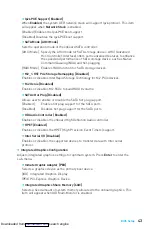
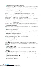
CPU GT Loadline Calibration Control [Auto]   


The voltage of the GPU embeeded in CPU will decrease proportionally according 

to GPU loading. Higher load-line calibration could get higher voltage and good 

overclocking performance, but increase the temperature of the CPU and VRM. 


f

CPU Core/ GT Voltage Mode [Auto]*

Selects the control mode for CPU Core/ GT voltages. 
[Auto]  


This setting will be configured automatically by BIOS.

[Adaptive Mode]  

Sets the adaptive voltage automatically for optimizing the system    

 performance. 

[Override Mode]  

Allows you to set the voltage manually.

[Offset Mode]   

Allows you to set the offset voltage and select the voltage offset  

 mode. 

[Ad Offset ]   Sets the adaptive voltage automatically and allows you to set the    


offset voltage.

[Ov Offset ]   Allows you to set the voltage and the offset voltage manually.


f

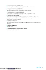
CPU Voltages control [Auto] 

These options allows you to set the voltages related to CPU. If set to 

Auto

,  BIOS will 

set these voltages automatically or you can set it manually. 


f

DRAM Voltages control [Auto] 

These options allows you to set the voltages related to memory. If set to 

Auto

,  BIOS 

will set these voltages automatically or you can set it manually. 


f

PCH Voltages control [Auto] (optional)

These options allows you to set the voltages related to PCH. If set to 

Auto

,  BIOS will 

set these voltages automatically or you can set it manually. 


f

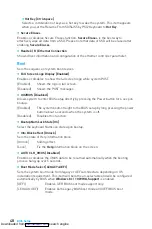
OC Quick View Timer [3 Sec]* 

Sets the duration of OC setting values showed on the screen.


f

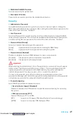
CPU Specifications

Press 

Enter

 to enter the sub-menu. This sub-menu displays the information of 

installed CPU. You can also access this information menu at any time by pressing [F4]. 

Read only.


f

CPU Technology Support

Press 

Enter 

to enter the sub-menu. The sub-menu shows the key features of 

installed CPU. Read only.


f

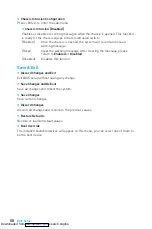
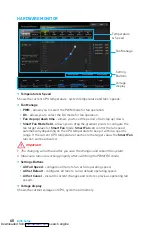
MEMORY-Z

Press 

Enter

 to enter the sub-menu. This sub-menu displays all the settings and 

timings of installed memory. You can also access this information menu at any time by 

pressing [F5]. 


f

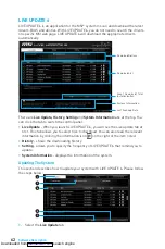
DIMMA1/A2/B1/B2 Memory SPD

Press 

Enter

 to enter the sub-menu. The sub-menu displays the information of 

installed memory. Read only.

Downloaded from 

ManualsNet.com

 search engine

Summary of Contents for Z270-A PRO

Page 1: ...rboard Check to make sure your motherboard box contains the following items If something is missing contact your dealer as soon as possible SATA Cable x2 Drivers Utilities Disc Motherboard User Guide...

Page 2: ...ation is completed This could cause permanent damage to the components as well as injury to the user y If you need help during any installation step please consult a certified computer technician y Al...

Page 3: ...4 Memory Graphics Card SATA Hard Disk Drive SATA DVD Drive A Package of Screws Phillips Screwdriver Chassis Power Supply Unit CPU Fan Thermal Paste Quick Start Preparing Tools and Components Downloade...

Page 4: ...4 Quick Start http youtu be bf5La099urI Installing a Processor 1 2 3 6 4 5 7 8 9 Downloaded from ManualsNet com search engine...

Page 5: ...5 Quick Start 1 1 2 2 3 3 Installing DDR4 memory http youtu be T03aDrJPyQs DIMMB2 DIMMB2 DIMMB1 DIMMA2 DIMMA2 DIMMA2 DIMMA1 Downloaded from ManualsNet com search engine...

Page 6: ...er LED 3 HDD LED 4 Power LED 5 Reset Switch 6 Power Switch 7 Reset Switch 8 Power Switch 9 Reserved 10 No Pin R E S E T S W P O W E R S W P O W E R L E D P O W E R L E D H D D L E D HDD LED RESET SW J...

Page 7: ...7 Quick Start BAT1 Installing the Motherboard 1 2 Downloaded from ManualsNet com search engine...

Page 8: ...8 Quick Start Installing SATA Drives http youtu be RZsMpqxythc 1 2 3 4 5 Downloaded from ManualsNet com search engine...

Page 9: ...9 Quick Start 1 Installing a Graphics Card http youtu be mG0GZpr9w_A 2 3 4 5 6 Downloaded from ManualsNet com search engine...

Page 10: ...10 Quick Start Connecting Peripheral Devices Downloaded from ManualsNet com search engine...

Page 11: ...11 Quick Start Connecting the Power Connectors http youtu be gkDYyR_83I4 ATX_PWR1 CPU_PWR1 Downloaded from ManualsNet com search engine...

Page 12: ...12 Quick Start Power On 1 4 2 3 Downloaded from ManualsNet com search engine...

Page 13: ...Audio Ports Configuration 20 Realtek HD Audio Manager 21 Overview of Components 23 CPU Socket 25 DIMM Slots 26 PCI_E1 6 PCIe Expansion Slots 27 M2_1 M 2 Slot Key M 28 SATA1 6 SATA 6Gb s Connectors 29...

Page 14: ...Software Description 61 Installing Windows 7 8 1 10 61 Installing Drivers 61 Installing Utilities 61 LIVE UPDATE 6 62 COMMAND CENTER 64 MSI SMART TOOL 68 MYSTIC LIGHT 70 RAMDISK 71 X BOOST 72 NETWORK...

Page 15: ...D port supports a maximum resolution of 1920x1200 60Hz y 1x DisplayPort supports a maximum resolution of 4096x2304 24Hz 2560x1600 60Hz 3840x2160 60Hz 1920x1200 60Hz Multi GPU y Supports 2 Way AMD Cro...

Page 16: ...3 1 Gen1 Type A ports y 1x VGA port y 1x DVI D port y 1x DisplayPort y 1x LAN RJ45 port y 2x USB 2 0 ports y 6x audio jacks Internal Connectors y 1x 24 pin ATX main power connector y 1x 8 pin ATX 12V...

Page 17: ...tures y 1x 128 Mb flash y UEFI AMI BIOS y ACPI 5 0 PnP 1 0a SM BIOS 2 8 y Multi language Software y Drivers y SUPER CHARGER y FAST BOOT y COMMAND CENTER y LIVE UPDATE 6 y MSI SMART TOOL y X BOOST y MY...

Page 18: ...twork Manager y Intel OptaneTM Memory Ready y Turbo M 2 y M 2 Genie y Pump Fan y Smart Fan Control y PCI E Steel Armor y Muitl GPU CrossFire Technology y DDR4 Boost y OC Genie 4 y X Boost y Military C...

Page 19: ...1 x M 2 6 x USB 2 0 PCI Express Bus P S2 Mouse Keyboard Audio Jacks DMI 3 0 Z270 CPU NV6795 Super I O Realtek ALC892 x1 x1 x1 PCI Express Bus VGA DisplayPort DVI D x1 PCIe x1 slot PCIe x1 slot PCIe x1...

Page 20: ...ked Blinking Data activity Speed LED Status Description Off 10 Mbps connection Green 100 Mbps connection Orange 1 Gbps connection LAN Port LED Status Table Audio Ports Configuration Audio Ports Channe...

Page 21: ...of anticipated sound effect for both output and input device y Main Volume controls the volume or balance the right left side of the speakers that you plugged in front or rear panel by adjust the bar...

Page 22: ...NPUT Rear Front Side Center Subwoofer Audio jacks to headphone and microphone diagram Audio jacks to stereo speakers diagram Audio jacks to 7 1 channel speakers diagram AUDIO INPUT Downloaded from Man...

Page 23: ...1 PCI_E6 CPU Socket CPU_PWR1 ATX_PWR1 JUSB3 SYS_FAN1 JUSB1 JBAT1 JUSB4 SATA 3 4 SATA2 SATA1 SATA 5 6 M2_1 DIMMA1 DIMMA2 DIMMB1 DIMMB2 SYS_FAN4 SYS_FAN2 EZ Debug LED JCI1 JFP1 JFP2 CPU_FAN1 PUMP_FAN1 J...

Page 24: ...ront Audio Connector 33 JBAT1 Clear CMOS Reset BIOS Jumper 34 JCI1 Chassis Intrusion Connector 33 JCOM1 Serial Port Connector 30 JFP1 JFP2 Front Panel Connectors 29 JLPT1 Parallel Port Connector 35 JT...

Page 25: ...with the CPU before booting your system y Overheating can seriously damage the CPU and motherboard Always make sure the cooling fans work properly to protect the CPU from overheating Be sure to apply...

Page 26: ...the maximum capacity of addressable memory is 4GB or less for 32 bit Windows OS due to the memory address limitation Therefore we recommended that you to install 64 bit Windows OS if you want to insta...

Page 27: ...rformance using the PCI_E1 slot is recommended y When adding or removing expansion cards always turn off the power supply and unplug the power supply power cable from the power outlet Read the expansi...

Page 28: ...Slot Key M Installing M 2 module 1 2 3 30 3 Tighten the base screw into the hole of the distance to the M 2 slot as the length your M 2 module 4 Insert your M 2 module into the M 2 slot at a 30 degre...

Page 29: ...Data loss may result during transmission otherwise y SATA cables have identical plugs on either sides of the cable However it is recommended that the flat connector be connected to the motherboard for...

Page 30: ...und 7 12V 4 Ground 8 12V Important Make sure that all the power cables are securely connected to a proper ATX power supply to ensure stable operation of the motherboard CPU_PWR1 ATX_PWR1 Power Connect...

Page 31: ...wer 10 NC 20 No Pin Important Note that the Power and Ground pins must be connected correctly to avoid possible damage JUSB1 2 USB 2 0 Connectors These connectors allow you to connect USB 2 0 ports on...

Page 32: ...nnector to PWM or DC Mode Switching fan mode and adjusting fan speed You can switch between PWM mode and DC mode and adjust fan speed in BIOS HARDWARE MONITOR Select PWM mode or DC mode Important Make...

Page 33: ...nnect the JCI1 connector to the chassis intrusion switch sensor on the chassis 2 Close the chassis cover 3 Go to BIOS SETTINGS Security Chassis Intrusion Configuration 4 Set Chassis Intrusion to Enabl...

Page 34: ...more details and usages JBAT1 Clear CMOS Reset BIOS Jumper There is CMOS memory onboard that is external powered from a battery located on the motherboard to save system configuration data If you wan...

Page 35: ...ector This connector allows you to connect the optional parallel port with bracket EZ Debug LED These LEDs indicate the status of key components during booting process When an error is occurred the co...

Page 36: ...ds to enter BIOS setup y Press Delete key when the Press DEL key to enter Setup Menu F11 to enter Boot Menu message appears on the screen during the boot process y Use MSI FAST BOOT application Click...

Page 37: ...g POST 2 Insert the USB flash drive that contains the update file into the computer 3 Select the M FLASH tab and click on Yes to reboot the system and enter the flash mode 4 Select a BIOS file to perf...

Page 38: ...P Extreme Memory Profile Switch the outer circle to select the X M P profile This switch will only be available if the X M P supported memory module is installed y Setup Mode switch press this tab or...

Page 39: ...Monitor menu that allows you to manually control the fan speed by percentage y Favorites press the F3 key to enter Favorites menu It allows you to create personal BIOS menu where you can save and acce...

Page 40: ...Overview section y BIOS menu selection the following options are available SETTINGS allows you to specify the parameters for chipset and boot devices OC allows you to adjust the frequency and voltage...

Page 41: ...ime format is hour minute second f SATA PortX M2_X Shows the information of connected SATA M 2 devices Important If the connected SATA device is not displayed turn off computer and re check SATA cable...

Page 42: ...to another color to indicate the S3 state Blinking The power LED blinks to indicate the S3 state f Integrated Peripherals Sets integrated peripherals parameters such as LAN HDD USB and audio Press Ent...

Page 43: ...to build RAID 0 volume fSATAx Hot Plug Disabled Allows user to enable or disable the SATA hot plug support Enabled Enables hot plug support for the SATA ports Disabled Disables hot plug support for t...

Page 44: ...ble the legacy USB support Enabled Enable the USB support under legacy mode Disabled The USB devices will be unavailable under legacy mode f Super IO Con guration Sets system Super I O chip parameters...

Page 45: ...s while encountering the AC power loss Power Off Leaves the system in power off state after restoring AC power Power On Boot up the system after restoring AC power Last State Restores the system to th...

Page 46: ...Manages the onboard Graphics Output Protocol GOP Press Enter to enter the sub menu This sub menu will appear when Windows 8 1 10 WHQL Support is enabled fSecure Boot Sets the Windows secure boot to p...

Page 47: ...r USB devices which are supported by third party integrated chips Enabled Enables the system to be awakened from the power saving modes when activity or input signal of PCIe device is detected Disable...

Page 48: ...by pressing the Power button for 4 sec pon bootup Enabled The system boots straight to the BIOS setup by long pressing the power button about 4 seconds when the system is off Disabled Disables this fu...

Page 49: ...Enables or disables the clear CMOS behavior to clear a set password Enabled The password will be erased after clear CMOS Disabled The password will always be kept Important When selecting the Administ...

Page 50: ...After clearing the message please return to Enabled or Disabled Disabled Disables this funcion Save Exit f Discard Changes and Exit Exit BIOS setup without saving any change f Save Changes and Reboot...

Page 51: ...of Expert mode f CPU Ratio Apply Mode All Core Sets applied mode for CPU ratio This item only appears when a CPU that supports Turbo Boost is installed All Core Activate the CPU Ratio field All CPU co...

Page 52: ...ed GT Frequency Shows the adjusted integrated graphics frequency Read only f Misc Setting Press Enter or key to open or close the following 3 items related to CPU features fEIST Enabled Enables or dis...

Page 53: ...timized memory preset f Advanced DRAM Con guration Press Enter to enter the sub menu User can set the memory timing for each all memory channel The system may become un stable or un bootable after cha...

Page 54: ...s automatically or you can set it manually f DRAM Voltages control Auto These options allows you to set the voltages related to memory If set to Auto BIOS will set these voltages automatically or you...

Page 55: ...ion technology Enabled Enables Intel Virtualization technology and allows a platform to run multiple operating systems in independent partitions The system can function as multiple systems virtually D...

Page 56: ...this function fPackage C State limit Auto This item allows you to select a CPU C state level for power saving when system is idle The options of C state depend on the installed CPU This item appears w...

Page 57: ...Turbo Boost mode fCPU Current Limit A Auto Sets maximum current limit of CPU package in Turbo Boost mode When the current is over the speci ed value the CPU will automatically reduce the core frequen...

Page 58: ...BIOS 1 Insert the USB flash drive that contains the update file into the computer 2 Click on M FLASH tab a demand message will be prompted Click on Yes to reboot and enter the flash mode 3 The system...

Page 59: ...le fLoad Overclocking Profile 1 2 3 4 5 6 Load the current overclocking pro le fClear Overclocking Profile 1 2 3 4 5 6 Clear the current overclocking profile f OC Pro le Load from ROM Load OC profile...

Page 60: ...l the fan speed automatically depending on the CPU temperature to keep it with in a specific range If the current CPU temperature reaches to the target value the Smart Fan function will be activated I...

Page 61: ...ct your optical drive from the Boot Menu 7 Press any key when screen shows Press any key to boot from CD or DVD message 8 Follow the instructions on the screen to install Windows 7 8 1 10 Installing D...

Page 62: ...u can click the tab to switch the control panel y Live Update When you launch LIVE UPDATE 6 you will see the Live update tab at first This tab allows you to select files to download You can also read...

Page 63: ...can specify a download directory 7 When downloading you will see the screen below It may take several moments to complete the process 8 To install the applications simply unpack the packages and insta...

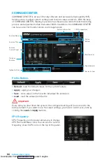
Page 64: ...ture Next Feature Profile Buttons Option Buttons Page Indicator Resize Corner Profile Buttons y Default load the default values for the current feature y Apply apply your changes y Save store values i...

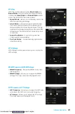
Page 65: ...ot will create strip chart in real time y System Fan Button to open the system fan control panel in new window y Fan Tune Button to automatically optimize the smart fan setting IGP Frequency GT Voltag...

Page 66: ...rning and Mobile Control icons will appear y Record allows you to monitor the status of voltage fan speed and temperature in real time To filter record charts select the check box next to the items Wh...

Page 67: ...le device and connect to SoftAP with the SSID 6 Run MSI COMMAND CENTER APP on your mobile device 7 Find the IP address on the SoftAP Management Setting area and enter the IP address on your MSI COMMAN...

Page 68: ...rive Step1 Choose source folder y In the Source folder box type the name and path of your Windows ISO file or click Browse button and select the file from the dialog box This option will copy all Wind...

Page 69: ...o create a software RAID 1 Use checkboxs to select the disks you want included in your RAID 2 Choose Speed Up or Backup for RAID type y Speed Up RAID0 y Backup RAID1 3 Click Start 4 When prompt Finish...

Page 70: ...OFF the LED function y LED Area Selection separately controls each segment of LEDs on your motherboard graphics cards and extend LED strip y LED effects switches LEDs on or off y Styles select the LED...

Page 71: ...rmat of the RAM disk y Option select browser temporary files to save load on the RAM disk You can also add software files to improve reading speed y Backup specify backup and restore settings to preve...

Page 72: ...ormance mode to meet the current system environment Setting Performance information Performance mode y Performance mode moves over the mouse to any one of performance mode and click on the ON button t...

Page 73: ...windows starts y USB SPEED UP supports faster data transfer rates of the USB storage devices y STORAGE BOOST supports faster access speed to storage device Important y Please note that you can only se...

Page 74: ...f c allows you to monitor network bandwidth usage y Network Test allows you to setup bandwidth control y Advanced Setting allows you to expand RWIN to accelerate download speed You can also block IP a...

Page 75: ...w 1 1 Click the Network Test block in NETWORK MANAGER 2 3 4 2 Click Test Network Speed button The test takes several minutes to test your network speed 3 Enter the testing results into Upload Speed an...

Page 76: ...ts the stability of your system Benchmarking analyzes and compares your system s performance against other system profiles Profiles manages sets of system settings y Tuning Controls displays the contr...

Page 77: ...e chipset BIOS version and graphic interface y Memory Tab shows memory type memory size channels memory frequency y SPD Tab shows specifications relating to each memory module connected to the motherb...

Page 78: ...nt OK Good OK Write performance Excellent Good OK Good Capacity utilization 100 50 67 1 1 n 50 Using Intel Rapid Storage Technology Option ROM First you need to set the SATA mode to RAID in BIOS to cr...

Page 79: ...r down arrow keys to scroll through the available values and pressing the Enter key to select and advance to the next field The available values range from 4KB to 128 KB in power of 2 increments The s...

Page 80: ...isks to Non RAID Select option Reset Disks to Non RAID from the main menu screen and press Enter to delete the RAID volume and remove any RAID structures from the drives Use the Space key to select th...

Page 81: ...covery Disk 2 Enable Only Master Disk Recovery mode will change from Continuous Update to On Request after you enable Only Recovery Disk or Only Master Disk Degraded RAID Array A RAID 1 RAID 5 or RAID...

Page 82: ...GB Non RAID Disk Select ESC Exit ENTER Select Menu 1 Create RAID Volume 2 Delete RAID Volume Degraded volume and disk available for rebuilding detected Selecting a disk initiates a rebuild Rebuild com...

Page 83: ...ter y If 1 long 2 short beeps are heard remove and reinstall the graphics card and then restart the computer y Test with another known working graphics card The computer does not boot after updating t...

Page 84: ...Rules Operation is subject to the following two conditions 1 This device may not cause harmful interference and 2 this device must accept any interference received including interference that may caus...

Page 85: ...o pueden ser depositados en los contenedores habituales de su municipio los fabricantes de equipos electr nicos est n obligados a hacerse cargo de dichos productos al termino de su per odo de vida MSI...

Page 86: ...keket a legk zelebbi gy jt helyre viheti ITALIANO Per proteggere l ambiente MSI da sempre amica della natura ti ricorda che In base alla Direttiva dell Unione Europea EU sullo Smaltimento dei Materia...

Page 87: ...ve the right to make changes without notice Technical Support If a problem arises with your system and no solution can be obtained from the user guide please contact your place of purchase or local di...

Reviews: