2-14
Hardware Setup
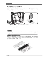
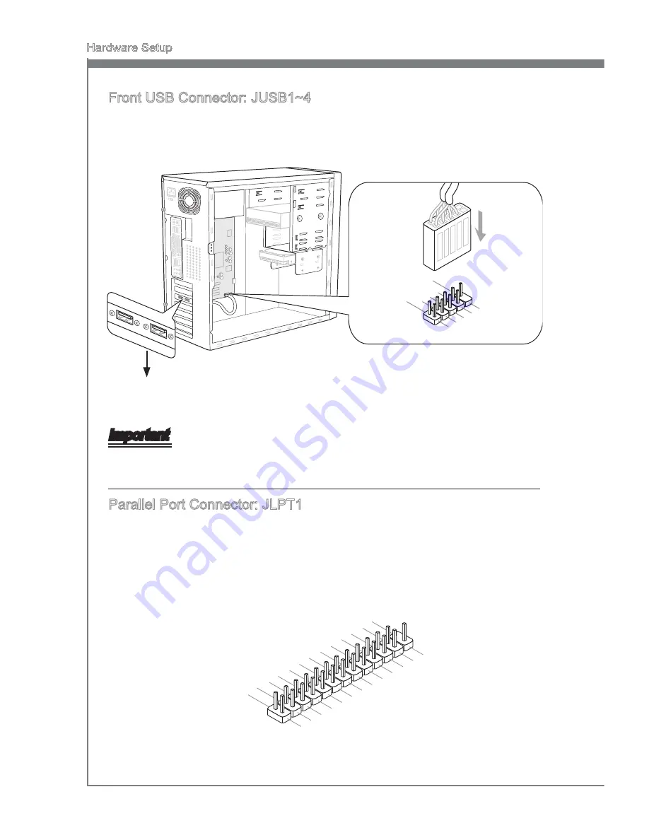
Front USB Connector: JUSB1~4
Ths connector, complant wth Intel
®
I/O Connectvty Desgn Gude, s deal for
connectng hgh-speed USB nterface perpherals such as USB HDD, dgtal cameras,
MP3 players, prnters, modems and the lke.
11
5
V
1.VC
C
3.US
B0-
10.N
C
5.US
B0+
7.Gro
und
9.No
Pin
8.Gro
und
6.US
B1+
4.US
B1-
2.VC
C
* The MB layout n ths figure s for reference only.
USB Bracket (optonal)
Important
Note that the pns of VCC and GND must be connected correctly to avod possble
damage.
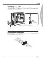
Parallel Port Connector: JLPT1
Ths connector s used to connect an optonal parallel port bracket. The parallel port
s a standard prnter port that supports Enhanced Parallel Port (EPP) and Extended
Capabltes Parallel Port (ECP) mode.
10.G
roun
d
14.G
roun
d
8.LP
T_S
LIN#
12.G
roun
d
6.PIN
IT#
4.ER
R#
2.AF
D#
24.G
roun
d
22.G
roun
d
26.N
o Pin
20.G
roun
d
18.G
roun
d
16.G
roun
d
1.RS
TB#
3.PR
ND0
5.PR
ND1
7.PR
ND2
9.PR
ND3
11.P
RND
4
13.P
RND
5
15.P
RND
6
17.P
RND
7
19.A
CK#
21.B
USY
23.P
E
25.S
LCT
Summary of Contents for Z68A-G43 (B3)
Page 1: ...H67A G43 B3 Z68A G43 B3 series MS 7750 v1 x Mainboard G52 77501X1...
Page 10: ......
Page 16: ......

