background image

Preface

MS-7750

Preface


x

Preface

MS-7750

Preface


Appendx A Realtek Audo .......................................................................... A-1

Installng the Realtek HD Audo Drver .................................................................A-2
Software Configuraton .........................................................................................A-3
Hardware Default Settng .....................................................................................A-5

Appendx B Intel RAID ................................................................................ B-1

Introducton ..........................................................................................................B-2
BIOS Configuraton ..............................................................................................B-3
Installng Drver ..................................................................................................B-10
Degraded RAID Array ........................................................................................B-12
System Acceleraton ..........................................................................................B-14
RST Synchronzaton .........................................................................................B-16

Summary of Contents for Z68A-G43 (B3)

Page 1: ...H67A G43 B3 Z68A G43 B3 series MS 7750 v1 x Mainboard G52 77501X1...

Page 2: ...tered trademark of Phoenix Technologies Ltd Sound Blaster is registered trademark of Creative Technology Ltd Realtek is registered trademark of Realtek Semiconductor Corporation JMicron is registered...

Page 3: ...ons and warnings on the equipment should be noted Never pour any liquid into the opening that can cause damage or cause electrical shock If any of the following situations arises get the equipment che...

Page 4: ...ct the interference by one or more of the measures listed below Reorient or relocate the receiving antenna Increase the separation between the equipment and receiver Connect the equipment into an outl...

Page 5: ...Elektronik Altger te nicht mehr als kommunale Abf lle entsorgt werden MSI hat europaweit verschiedene Sammel und Recyclingunternehmen beauftragt die in die Europ ische Union in Verkehr gebrachten Prod...

Page 6: ...e producten die de merknaam MSI dragen en verkocht zijn in de EU Deze goederen kunnen geretourneerd worden op lokale inzamelingspunten SRPSKI Da bi za titili prirodnu sredinu i kao preduze e koje vodi...

Page 7: ...m stn ch sb rn ch MAGYAR Annak rdek ben hogy k rnyezet nket megv dj k illetve k rnyezetv d k nt fell pve az MSI eml kezteti nt hogy Az Eur pai Uni EU 2005 augusztus 13 n hat lyba l p az elektromos s...

Page 8: ...Getting Started 1 1 Mainboard Specifications 1 2 Mainboard Layout 1 4 Packing Contents 1 5 Optional Accessories 1 5 Chapter 2 Hardware Setup 2 1 Quick Components Guide 2 2 Mounting Screw Holes 2 3 CPU...

Page 9: ...Installing the Realtek HD Audio Driver A 2 Software Configuration A 3 Hardware Default Setting A 5 Appendix B Intel RAID B 1 Introduction B 2 BIOS Configuration B 3 Installing Driver B 10 Degraded RA...

Page 10: ......

Page 11: ...1 X ATX mainboard These Series mainboards are based on Intel H67 Z68 chipsets for optimal system efficiency Designed to fit the advanced Intel LGA1155 processor the Series deliver a high performance a...

Page 12: ...onents please visit http www msi com service test report LAN Supports LAN 10 100 1000 Fast Ethernet by Realtek RTL8111E Audio HD audio codec integrated by Realtek ALC887 ALC892 optional Flexible 8 cha...

Page 13: ...rs 1 Chassis Intrusion connector 1 S PDIF Out connector 1 Front Panel Audio connector 1 TPM Module connector 1 Parallel port connector 1 Serial port connector Slots 2 PCIe 2 0 x16 slots PCI_E4 slot su...

Page 14: ...FP1 JFP2 JUSB1 JUSB2 JUSB3 JUSB4 JBAT1 DIMM1 DIMM2 DIMM3 DIMM4 Top VGA Port Bottom DVI D Port Top mouse Bottom keyboard Top LAN Jack Bottom USB2 0 ports T RS Out M CS Out B SS Out T M B Line In Line O...

Page 15: ...the model you purchased If you need to purchase the optional accessories please visit http www msi com index php to inquire the part numbers or consult the dealer Mainboard Driver Utility DVD User Gu...

Page 16: ......
Page 17: ...be careful in holding the components and follow ing the installation procedures For some components if you install in the wrong orientation the components will not work properly Use a grounded wrist...

Page 18: ...4 CPUFAN1 p 2 13 DDR3 p 2 7 JPWR2 p 2 9 JPWR1 p 2 9 SYSFAN1 p 2 13 SATA p 2 12 JFP1 JFP2 p 2 13 JUSB1 4 p 2 14 JSP1 p 2 15 JAUD1 p 2 15 JCI1 p 2 12 JTPM1 p 2 16 PCIe p 2 18 SYSFAN2 p 2 13 JBAT1 p 2 17...

Page 19: ...ations on chassis and then screw through the mainboard screw holes into the standoffs Important To prevent damage to the mainboard any contact between the mainboard circuit and chassis or unnecessary...

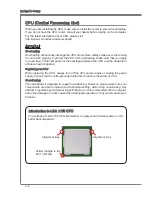
Page 20: ...e heatsink to enhance heat dissipation Replacing the CPU While replacing the CPU always turn off the ATX power supply or unplug the power supply s power cord from the grounded outlet first to ensure t...

Page 21: ...llation will cause the damage of your CPU mainboard Open the load lever 1 Lift the load lever up to fully open position 2 After confirming the CPU direction for correct mating put down the CPU in the...

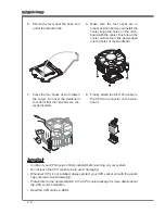
Page 22: ...rn over the mainboard to confirm that the clip ends are cor rectly inserted 7 Finally attach the CPU Fan cable to the CPU fan connector on the main board 8 Important Confirm if your CPU cooler is firm...

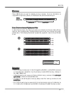
Page 23: ...e population rules for Dual Channel mode 1 DIMM1 DIMM2 DIMM3 DIMM4 2 DIMM1 DIMM2 DIMM3 DIMM4 Important DDR3 memory modules are not interchangeable with DDR2 and the DDR3 standard is not backwards comp...

Page 24: ...til the golden finger on the memory module is deeply inserted in the DIMM slot The plastic clip at each side of the DIMM slot will automatically close when the memory module is properly seated Manuall...

Page 25: ...3 3 V 1 3 3 V 1 4 1 2 V 2 3 3 V 1 5 G r o u n d 3 G r o u n d 1 6 P S O N 4 5 V 1 7 G r o u n d 5 G r o u n d 1 8 G r o u n d 6 5 V 1 9 G r o u n d 7 G r o u n d 2 2 5 V 1 0 1 2 V 2 0 R e s 8 P W R O...

Page 26: ...the USB 3 0 port VGA Port The DB15 pin female connector is provided for monitor DVI D Port The DVI D Digital Visual Interface Digital connector allows you to connect a LCD monitor It provides a high s...

Page 27: ...c data rate is selected Orange On 1000 Mbits sec data rate is selected Audio Ports These audio connectors are used for audio devices It is easy to differentiate between audio effects according to the...

Page 28: ...3 SATA4 Important Please do not fold the Serial ATA cable into 90 degree angle Otherwise data loss may occur during transmission Chassis Intrusion Connector JCI1 This connector connects to the chassis...

Page 29: ...r 4 N o u s e SYSFAN1 Important Please refer to the recommended CPU fans at processor s official website or consult the vendors for proper CPU cooling fan CPUFAN1 support Smart fan control You can ins...

Page 30: ...e pins of VCC and GND must be connected correctly to avoid possible damage Parallel Port Connector JLPT1 This connector is used to connect an optional parallel port bracket The parallel port is a stan...

Page 31: ...layout in this figure is for reference only S PDIF Out Bracket optional Front Panel Audio Connector JAUD1 This connector allows you to connect the front panel audio and is compliant with Intel Front P...

Page 32: ...I R Q 4 3 3 V P o w e r 2 3 V S t a n d b y p o w e r 1 L P C C l o c k 3 L P C R e s e t 5 L P C a d d r e s s d a t a p i n 0 7 L P C a d d r e s s d a t a p i n 1 9 L P C a d d r e s s d a t a p i...

Page 33: ...boot OS every time it is turned on If you want to clear the system configuration please temporarily short these two pins to clear data by using a metal object Important You can clear CMOS by touching...

Page 34: ...expansion cards make sure that you unplug the power sup ply first Read the documentation for the expansion card to configure any necessary hardware or software settings such as jumpers switches or BIO...

Page 35: ...you to configure the system for op timum use You may need to run the Setup program when An error message appears on the screen during the system booting up and requests you to run SETUP You want to ch...

Page 36: ...Important The items under each BIOS category described in this chapter are under continuous update for better system performance Therefore the description may be slightly dif ferent from the latest BI...

Page 37: ...ft of certain fields that means a sub menu can be launched from this field A sub menu contains additional options for a field parameter You can use arrow keys or mouse to highlight the field and press...

Page 38: ...ck Utilities icon to enter the menu This menu provides the useful utility for you to live update bios and hard disk backup Overclocking Click Overclocking icon to enter the menu Use this menu to speci...

Page 39: ...to reduce the CPU power consumption while idle Not all processors support Enhanced Halt state C1E Intel C State C state is a power management state that significantly reduces the power of the proces...

Page 40: ...consists of backing up all the partition on image files When the data is lost or problems occur you can restore the partition image to keep your system Boot Screen This item is used to select the boot...

Page 41: ...e note the overclocking behavior is not guaranteed Adjust CPU Ratio This item controls the multiplier that is used to determine the internal clock speed of the processor relative to the external or mo...

Page 42: ...OC Genie Button Operation This field is used to enable disable OC Genie function DRAM Frequency This item allows you to adjust the DRAM frequency Please note the overclocking be havior is not guarant...

Page 43: ...FC This setting determines the time RFC takes to read from and write to a memory cell tWR Minimum time interval between end of write data burst and the start of a precharge command Allows sense amplif...

Page 44: ...tion The greater the Spread Spectrum value is the greater the EMI is reduced and the system will become less stable For the most suitable Spread Spectrum value please consult your local EMI regulation...

Page 45: ...tem allows you to select the number of active processor cores Limit CPUID Maximum It is designed to limit the listed speed of the processor to older operating systems Execute Disable Bit Intel s Execu...

Page 46: ...essor automatically reduces its clock speed If you want to overclock your CPU set it to Disabled Intel C State C state is a power management state that significantly reduces the power of the processor...

Page 47: ...Simply click any icon to enter it and following the game rules to play it Important Before you enter to the Game menu please place the MSI Driver DVD that be included in the mainboard package into th...

Page 48: ...the date that you want usually the current date The format is day month date year day Day of the week from Sun to Sat determined by BIOS Read only month The month from Jan through Dec date The date fr...

Page 49: ...controls how long each PCI device can hold the bus before another takes over When set to higher values every PCI device can conduct transactions for a longer time and thus improve the effective PCI b...

Page 50: ...enable it and will provide you with the means to get to it via the various ACPI methods Integrated Graphics Configuration Press Enter to enter the sub menu Integrated Graphics Devices Configuration In...

Page 51: ...0 interfaced device in the operating system Super IO Configuration Press Enter to enter the sub menu Serial COM Port 0 Configuration Press Enter to enter the sub menu Serial COM Port0 This item allows...

Page 52: ...devices com ponents such as CPU temperature system temperature and all fans speeds Power Management Setup Press Enter to enter the sub menu EuP 2013 This item is designed for Energy Using Products Lot...

Page 53: ...SB device to wake up the system from S3 Sus pend to RAM sleep state Resume From S3 S4 S5 by PS 2 Mouse Keyboard These items determine whether the system will be awakened from what power sav ing modes...

Page 54: ...rt the selection and not enter a password To clear a set password just press Enter when you are prompted to enter the pass word A message will show up confirming the password will be disabled Once the...

Page 55: ...ws a still image logo on the full screen at boot Disabled Shows the POST messages at boot Boot Option Priorities Boot options You can select the boot priorities in these Boot items USB HardDisk Drive...

Page 56: ...the system Save Changes Use this item to save changes Discard Changes Use this item to abandon all changes Restore Defaults Use this item to load the optimized default values set by the BIOS vendor Bo...

Page 57: ...vides 10 channel DAC that simul taneously supports 7 1 sound playback and 2 channels of independent stereo sound output multiple streaming through the Front Out Left and Front Out Right chan nels Appe...

Page 58: ...ould look slightly different if you install the drivers in different operating systems Insert the application DVD into the DVD ROM drive The setup screen will automati cally appear Click Driver tab Cl...

Page 59: ...screen You may double click the icon and the GUI will pop up accordingly double click the icon It is also available to enable the audio driver by clicking the Realtek HD Audio Manager from the Control...

Page 60: ...just the bar Application Enhancement The array of options will provide you a complete guidance of anticipated sound effect for both output and input device Jack status panel This panel depicts all ren...

Page 61: ...S 7750 Appendix A Hardware Default Setting The following diagrams are audio back panel default setting Backpanel audio jacks to 2 channel speakers diagram Front Backpanel audio jacks to 4 channel spea...

Page 62: ...A 6 Realtek Audio Backpanel audio jacks to 6 channel speakers diagram Rear Front Center Subwoofer Backpanel audio jacks to 8 channel speakers diagram Rear Front Center Subwoofer Side Surround...

Page 63: ...This appendix will assist users in configuring and en abling RAID functionality and accelerating system on platforms Appendix B Intel RAID...

Page 64: ...byte level and also stripe error correction informa tion This results in excellent performance and good fault tolerance Level 5 is one of the most popular implementations of RAID RAID 10 Not one of th...

Page 65: ...olumes The Serial ATA RAID volume may be configured using the RAID Configuration utility stored within the Intel RAID Option ROM During the Power On Self Test POST the following message will appear fo...

Page 66: ...2 CREATE VOLUME MENU HELP Name RAID 1 Mirrors data redundancy Change TAB Next ESC Previous Menu ENTER Select RAID Level Disks Strip Size Capacity Sync Volume0 RAID1 Mirror Select Disks N A XXX X GB N...

Page 67: ...e available according to the selected RAID level Then select the capacity of the volume in the Capacity field The default value is the maximum volume capacity of the selected disks 3 4 5 CREATE VOLUME...

Page 68: ...0 RAID1 Mirror Select Disks N A XXX X GB N A Create Volume WARNING ALL DATA ON SELECTED DISKS WILL BE LOST Are you sure you want to create this volume Y N DISK VOLUME INFORMATION 4 Recovery Volume Opt...

Page 69: ...elect a RAID volume for deletion Then press Delete key to delete the selected RAID volume The following screen appears DELETE VOLUME MENU HELP Deleting a volume will reset the disks to non RAID Select...

Page 70: ...structures and revert it to a non RAID disk RESET RAID DATA WARNING Resetting a disk causes all data on the disk to be lost This does not apply to Recovery volumes Select the disks that should be rese...

Page 71: ...Disk enables recovery disk if available and disables master disk Enable Only Master Disk enables master disk if available and disables recovery disk Actions will result in change from Continuous Updat...

Page 72: ...ify Additional Device You should be prompted to insert a floppy disk containing the Intel RAID driver into the A drive Note For Windows XP you can use the USB floppy drive only For Windows Vista Windo...

Page 73: ...er tab click on Intel RAID Drivers The drivers will be automatically installed Confirming Windows Driver Installation From Windows open the Control Panel from My Computer followed by the System icon C...

Page 74: ...estination disk for rebuilding and then press ENTER 4 RAID Volumes ID Name Level Strip Size Status Bootable 0 Volume0 RAID 1 Mirror N A XXX XGB Degraded Yes Physical Disks Port Device Model Serial Siz...

Page 75: ...tem When prompted to rebuild the RAID volume click Yes The Intel Rapid Storage Technology application will be launched Right click the new hard drive and select Rebuild to this Disk The Rebuild Wizard...

Page 76: ...ugh there is only one hard drive you must set the SATA Mode to RAID in BIOS The OS must be installed in the RAID ready disk in order to use the SSD caching Follow these steps to enable system accelera...

Page 77: ...Accelerate 11 12 Click here Select the acceleration options 13 Click OK and reboot the system The page refreshes and reports the new acceleration configuration in the Acceleration View Important You c...

Page 78: ...ame Press s to synchronize data from the cache device to the Accelerated Disk Volume Press r to remove the Disk Volume Acceleration WARNING IT IS RECOMMENDED THAT YOU ERFORM A SYNCHRONIZATION BEFORE R...

Reviews: