background image

Français

Fr-35

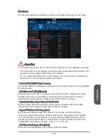
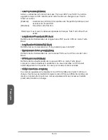
Internal VR OVP OCP Protection [Auto]

Active ou désactive la protection contre les surtensions ou la protection contre les 

surintensités pour le CPU VR (Voltage Regulator) interne.

[Auto] 

Ce réglage est configuré automatiquement par le BIOS.

[Enabled] 

Définit une limite de tension sur le CPU VR interne pour la protection 

contre les surtensions et contre les surintensités. 

[Disabled] 

Désactive cette fonction pour l'overclocking.

Internal VR Efficiency Management [Auto]

Active ou désactive la gestion d'efficacité du CPU VR interne.

[Auto] 

Ce réglage est configuré automatiquement par le BIOS.

[Enabled] 

Activer la gestion d'efficacité VR pour le contrôle d'économie d'énergie. 

[Disabled] 

Désactiver cette fonction.  

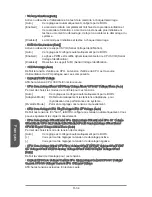
DRAM Voltage [Auto]

Définit la tension de mémoire. En "Auto", le BIOS définit automatiquement la tension 

de mémoire. Vous pouvez également la régler manuellement.

Current DRAM Voltage

Affiche la tension actuelle de la mémoire. En lecture seule.

CPU Memory Changed Detect [Enabled]

Active ou désactive le système pour l'envoi un message d'alerte au démarrage 

lorsque le CPU ou la mémoire a été remplacé.

[Enabled] 

Le système envoie un message d'alerte au démarrage. Il a ensuite 

besoin de ses réglages par défaut pour les nouveaux périphériques.

[Disabled] 

Désactive cette fonction et conserve les réglages BIOS.

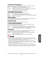
Spread Spectrum

Cette fonction réduit les interférences électromagnétiques EMI (Electromagnetic 

Interference) en réglant les impulsions du générateur d'horloge.

[Enabled] 

Active la fonction spread spectrum pour réduire le problème EMI 

(Electromagnetic Interference).

[Disabled] 

Améliore la capabilité d’overclocking de le base clock CPU.

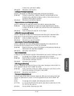
 Important

Si vous n’avez pas de problème d’EMI, laissez l’option sur [Disable], ceci vous 

permet d’avoir une stabilité du système et des performances optmales. Dans le cas 

contraire, choisissez Spread Spectrum pour réduire les EMI.
Plus la valeur Spread Spectrum est importante, plus les EMI sont réduites, et le 

système devient moins stable. Pour la valeur Spread Spectrum la plus convenable, 

veuillez consulter le reglement EMI local.
N’oubliez pas de désactiver la fonction Spread Spectrum si vous êtes en train 

d’overclocker parce que même un battement léger peut causer un accroissement 

temporaire de la vitesse de l’horloge qui verrouillera votre processeur overclocké.

Summary of Contents for Z87M-G43 Series

Page 1: ...Z87M G43 H87M G43 B85M G43 Motherboard G52 78231X3 Preface...

Page 2: ...ion Intel is registered trademarks of Intel Corporation Windows is registered trademarks of Microsoft Corporation AMI is registered trademark of American Megatrends Inc Award is a registered trademark...

Page 3: ...within minutes Better yet the power calculator provides accurate estimates of power unit capacity for DIY users Technical Support If a problem arises with your system and no solution can be obtained f...

Page 4: ...Do not place anything over the power cord Always Unplug the Power Cord before inserting any add on card or module All cautions and warnings on the equipment should be noted Never pour any liquid into...

Page 5: ...hich can be determined by turning the equipment off and on the user is encouraged to try to correct the interference by one or more of the measures listed below Reorient or relocate the receiving ante...

Page 6: ...ent and its antenna must not be co located or operating in conjunction with any other antenna or transmitter European Community Compliance Statement The equipment complies with the RF Exposure Require...

Page 7: ...ld not be disposed of as unsorted household waste Please use the public collection system to return recycle or treat them in compliance with the local regulations Battery Information Chemical Substanc...

Page 8: ...ronik Altger te nicht mehr als kommunale Abf lle entsorgt werden MSI hat europaweit verschiedene Sammel und Recyclingunternehmen beauftragt die in die Europ ische Union in Verkehr gebrachten Produkte...

Page 9: ...de producten die de merknaam MSI dragen en verkocht zijn in de EU Deze goederen kunnen geretourneerd worden op lokale inzamelingspunten SRPSKI Da bi za titili prirodnu sredinu i kao preduze e koje vo...

Page 10: ...sb rn ch MAGYAR Annak rdek ben hogy k rnyezet nket megv dj k illetve k rnyezetv d k nt fell pve az MSI eml kezteti nt hogy Az Eur pai Uni EU 2005 augusztus 13 n hat lyba l p az elektromos s elektroni...

Page 11: ...De 2 Anschluss bersicht De 5 R cktafel bersicht De 7 CPU Prozessor De 9 Speicher De 13 Schraubenl cher f r die Montage De 14 Stromversorgung De 15 Erweiterungssteckpl tze De 16 Video Grafikkarten De...

Page 12: ...llation A 1 CPU A 2 Memory Speicher M moire A 4 Motherboard Carte m re A 5 Power Connector ATX Stromanshcluss Connecteurs d alimentation P A 7 SATA HDD A 9 mSATA SSD A 10 Front Panel Connector Frontpa...

Page 13: ...Z87M G43 H87M G43 B85M G43 Series motherboards are based on Intel Z87 H87 B85 chipset for optimal system efficiency Designed to fit the advanced Intel LGA1150 processor the Z87M G43 H87M G43 B85M G43...

Page 14: ...maximum resolution of 4096x2160 24Hz 24bpp 2560x1600 60Hz 24bpp 1920x1080 60Hz 36bpp 1x DisplayPort supporting a maximum resolution of 4096x2160 24Hz 24bpp 3840x2160 60Hz 24bpp Multi GPU Support Suppo...

Page 15: ...rts for B85M G43 1x USB 3 0 connector supports additional 2 USB 3 0 ports 1x 4 pin CPU fan connector 2x 4 pin system fan connectors 1x Clear CMOS jumper 1x Front panel audio connector 2x System panel...

Page 16: ...Trend Micro SafeSync Sound Blaster Cinema for Z87M G43 Network genie Small Business Advantage for H87M G43 B85M G43 Form Factor Micro ATX Form Factor 9 6 in x 9 6 in 24 4 cm x 24 4 cm For the latest i...

Page 17: ...Quick Guide CPUFAN1 JFP1 JCI1 PCI_E1 PCI_E2 PCI_E3 PCI_E4 JFP2 JPWR1 SATA3_4 SATA5_6 JPWR2 CPU Socket Back Panel SYSFAN2 JUSB1 JUSB2 optional DIMM4 DIMM3 DIMM2 DIMM1 JUSB4 SYSFAN1 JBAT1 JTPM1 JLPT1 JC...

Page 18: ...onnector En 22 JBAT1 Clear CMOS Jumper En 25 JCI1 Chassis Intrusion Connector En 24 JCOM1 Serial Port Connector En 23 JFP1 JFP2 System Panel Connectors En 20 JLPT1 Parallel Port Connector En 24 JPWR1...

Page 19: ...a USB cable is used it must be USB 3 0 compliant LAN Port The standard RJ 45 LAN jack is for connecting to a Local Area Network LAN LINK ACT LED SPEED LED LED LED Status Description Link Activity LED...

Page 20: ...er to the monitor s manual for more information Important This platform supports dual display and triple display function Extend mode Extend the desktop to the second and third monitor Clone mode Moni...

Page 21: ...cord to ensure the safety of the CPU Overclocking This motherboard is designed to support overclocking Before attempting to overclock please make sure that all other system components can tolerate ove...

Page 22: ...ng installation can damage both the CPU and the motherboard 1 Push the load lever down to unclip it and lift to the fully open position 2 The load plate will automatically lift up as the load lever is...

Page 23: ...he retention knob Close and engage the load lever Alignment Key CPU notches Retention knob 5 When you press down the load lever the PnP cap will automatically pop up from the CPU socket Do not discard...

Page 24: ...connector on the motherboard 8 Place the heatsink on the motherboard with the fan s cable facing towards the fan connector and the fasteners matching the holes on the motherboard CPU fan connector 9 P...

Page 25: ...o data bus channels simultaneously Enabling Dual Channel mode can enhance system performance The following illustrations explain the population rules for Dual Channel mode DIMM2 DIMM4 DIMM1 DIMM2 DIMM...

Page 26: ...motherboard with the screws provided with your computer case The locations of the screw holes on the motherboard are shown below For more information please refer to the manual that came with the com...

Page 27: ...orrectly the clip on the power cable should be hooked on the motherboard s power connector 4 1 2 V 2 G r o u n d 3 1 2 V 1 G r o u n d 1 3 3 3 V 1 3 3 V 1 4 1 2 V 2 3 3 V 1 5 G r o u n d 3 G r o u n d...

Page 28: ...The PCIe slot supports the PCIe interface expansion card PCIe 2 0 x1 Slot PCIe 3 0 x16 Slot PCIe 2 0 x16 Slot Important When adding or removing expansion cards always turn off the power supply and unp...

Page 29: ...ansion slot s the video card will use Locate the expansion slot s on the motherboard Remove any protective expansion slot covers from the computer case Line up the video card on top of the expansion s...

Page 30: ...Many SATA devices also need a power cable from the power supply Such devices include disk drives HDD solid state drives SSD and optical drives CD DVD Blu Ray Please refer to the device s manual for fu...

Page 31: ...be plugged into any available system fan connector 1 G r o u n d 2 1 2 V 3 S e n s e 4 S p e e d C o n t r o l Important Please refer to your processor s official website or consult your vendor to fi...

Page 32: ...n Watch the video to learn how to Install front panel connectors http youtu be DPELIdVNZUI 1 3 1 0 N o P i n 5 R e s e t S w i t c h H D D L E D P o w e r S w i t c h P o w e r L E D 7 9 R e s e r v e...

Page 33: ...channels to quickly charge your connected device Please note that when the SuperCharger application is turned on data transmission and synchronization over the JUSB1 connector will not function To ena...

Page 34: ...U S B 3 _ T X _ C _ D P 1 3 G r o u n d 1 2 U S B 2 0 1 1 U S B 2 0 Important Note that the VCC and GND pins must be connected correctly to avoid possible damage To use a USB 3 0 device you must conne...

Page 35: ...V S t a n d b y p o w e r 1 L P C C l o c k 3 L P C R e s e t 5 L P C a d d r e s s d a t a p i n 0 7 L P C a d d r e s s d a t a p i n 1 9 L P C a d d r e s s d a t a p i n 2 1 1 L P C a d d r e s s...

Page 36: ...6 N o P i n 2 0 G r o u n d 1 8 G r o u n d 1 6 G r o u n d 1 R S T B 3 P R N D 0 5 P R N D 1 7 P R N D 2 9 P R N D 3 1 1 P R N D 4 1 3 P R N D 5 1 5 P R N D 6 1 7 P R N D 7 1 9 A C K 2 1 B U S Y 2 3...

Page 37: ...system can automatically boot into the operating system OS every time it is turned on If you want to clear the system configuration set the jumpers to clear the CMOS RAM Keep Data Clear Data 1 1 Impor...

Page 38: ...ties Total Installer Total Installer is very easy to use and does a great job of finding necessary drivers Please follow the steps below to install drivers and utilities for your new computer Insert M...

Page 39: ...f the message disappears before you respond and you still need to enter BIOS restart the system by turning the computer OFF then back ON or pressing the RESET button You may also restart the system by...

Page 40: ...OS version BIOS menu selection The following options are available SETTINGS Uses this menu to specify the parameters for chipset and boot devices OC This menu contains the frequency and voltage adjust...

Page 41: ...optimized overclocking profile Model Name Shows the model name of motherboard Sub Menu Scroll bar General Help Sub menu If you find a point symbol to the left of certain items that means a sub menu ca...

Page 42: ...ouble click the left button Select Icon Field Esc Click the right button Jump to the Exit menu or return to the previous from a submenu Increase the numeric value or make changes Decrease the numeric...

Page 43: ...e note that overclocking behavior and stability is not guaranteed This item appears when the installed processor supports this function Current CPU Base Clock Strap for Z87M G43 Shows the current CPU...

Page 44: ...performance automatically above rated specifications when system request the highest performance state Disabled Disables this function Enhanced Turbo Auto Enables or disables Enhanced Turbo function f...

Page 45: ...XMP memory module DRAM Timing Mode Auto Selects the memory timing mode Auto DRAM timings will be determined based on SPD Serial Presence Detect of installed memory modules Link Allows user to configu...

Page 46: ...age Mode CPU GT Voltage Mode Auto Selects the control modes for these voltages Auto This setting will be configured automatically by BIOS Adaptive Mode Sets adaptive voltages automatically for optimiz...

Page 47: ...e during boot when the CPU or memory has been replaced Enabled The system will issue a warning message during boot and than needs to load the default settings for new devices Disabled Disables this fu...

Page 48: ...ystem performance is highly improved Enable Enables Intel Hyper Threading technology Disabled Disables this item if the system does not support HT function Active Processor Cores All This item allows...

Page 49: ...r disables the Intel adaptive thermal monitor function to protect the CPU from overheating Enabled Throttles down the CPU core clock speed when the CPU is over the adaptive temperature Disabled Disabl...

Page 50: ...ong Duration Maintained s Auto Sets the maintaining time for Long duration power Limit W Short Duration Power Limit W Auto Sets the short duration TDP power limit for CPU in Turbo Boost mode CPU Curre...

Page 51: ...G43 B85M G43 Motherboard basiert auf dem Intel Z87 H87 B85 Chipsatz und erm glicht so ein optimales und effizientes System Entworfen um den hochentwickelten Intel LGA1150 Prozessor zu unterst tzen ste...

Page 52: ...4Hz 24bpp 2560x1600 60Hz 24bpp 1920x1080 60Hz 36bpp 1x DisplayPort Anschluss unterst tzt eine maximale Aufl sung von 4096x2160 24Hz 24bpp 3840x2160 60Hz 24bpp Multi GPU Unterst tzt AMD CrossFireTM Tec...

Page 53: ...85M G43 USB 3 0 Anschluss x1 unterst tzt zus tzliche 2 USB 3 0 Ports 4 poliger CPU L fter Anschluss x1 4 poliger System L fter Anschl sse x2 Steckbr cke zur CMOS L schung x1 Audioanschluss des Frontpa...

Page 54: ...rend Micro SafeSync Sound Blaster Cinema F r Z87M G43 Network genie Intel Small Business Advantage F r H87M G43 B85M G43 Form Faktor ATX Form Faktor 9 6 Zoll x 9 6 Zoll 24 4 cm x 24 4 cm Weitere CPU I...

Page 55: ...s bersicht CPUFAN1 JFP1 JCI1 PCI_E1 PCI_E2 PCI_E3 PCI_E4 JFP2 JPWR1 SATA3_4 SATA5_6 JPWR2 CPU Sockel R cktafel SYSFAN2 JUSB1 JUSB2 optional DIMM4 DIMM3 DIMM2 DIMM1 JUSB4 SYSFAN1 JBAT1 JTPM1 JLPT1 JCOM...

Page 56: ...ss des Frontpanels De 22 JBAT1 Steckbr cke zur CMOS L schung De 25 JCI1 Geh usekontaktanschluss De 24 JCOM1 Serieller Anschluss De 23 JFP1 JFP2 Systemtafelanschl sse De 20 JLPT1 Parallele Schnittstell...

Page 57: ...nschluss an LAN Port Die Standard RJ 45 Buchse dient zur Verbindung in einem lokalen Netzwerk LAN LINK ACT LED SPEED LED LED LED Status Bezeichnung Link Activity LED Verbindung Aktivit t LED Aus Keine...

Page 58: ...ttform unterst tzt die Ausgabe ber 2 oder 3 Displays Erweiterter Modus Erweiterung des Desktops auf einen zweiten und dritten Monitor Clone Modus Monitore zeigen das gleiche Bild HDMI DisplayPort HDMI...

Page 59: ...d wurde so entworfen dass es bertakten unterst tzt Stellen Sie jedoch bitte sicher dass die betroffenen Komponenten mit den abweichenden Einstellungen w hrend des bertaktens zurecht kommen Von jedem V...

Page 60: ...ehlerhafter Einbau f hrt zu Sch den an der CPU und dem Motherboard 1 Dr cken Sie den Verschlusshebel nach unten zum ffnen des Hebels und ffnen Sie anschlie end die Abdeckplatte 2 Die Abdeckplatte soll...

Page 61: ...Justiermarkierungen CPU Kerben R ckhalteknopf 5 Wenn Sie den Verschlusshebel herunterdr cken wird die PnP Abdeckung aus dem CPU Sockel automatisch getrennt Bitte bewahren Sie die PnP Abdeckung Setzen...

Page 62: ...luss auf dem Motherboard ausfinding 8 Setzen Sie den K hlk rper auf die CPU und beachten Sie die bereinstimmung der L fterverankerungen mit den daf r vorgsehenen L chern auf der Motherboard Platine 9...

Page 63: ...Aktivierung des Dual Kanal Modus wird die Leistung Ihres Systems verbessert Bitte beachten Sie die folgenden Abbildungen zur Veranschaulichung der Installationsvorgaben im Dual Kanal Modus DIMM2 DIMM...

Page 64: ...oard mit den dem Geh use beiliegenden Schrauben fest Die Positionen der Befestigungsl cher sehen Sie in der Zeichnung unten Weitere Informationen erfahren Sie ber Ihr Geh usehandbuch Wichtig Installie...

Page 65: ...erichtet ist Dr cken Sie dann den Anschluss des Netzteils fest nach unten um eine richtige Verbindung zu gew hrleisten 4 1 2 V 2 G r o u n d 3 1 2 V 1 G r o u n d 1 3 3 3 V 1 3 3 V 1 4 1 2 V 2 3 3 V 1...

Page 66: ...z unterst tzt PCIe Erweiterungskarten PCIe 2 0 x1 Steckplatz PCIe 3 0 x16 Steckplatz PCIe 2 0 x16 Steckplatz Wichtig Achten Sie darauf dass Sie den Strom abschalten und das Netzkabel aus der Steckdose...

Page 67: ...Suchen Sie einen entsprechenden freien Steckplatz auf Ihrem Motherboard Entfernen Sie eine eventuelle Schutzvorrichtung f r den Steckplatz im Geh use Positionieren Sie die Grafikkarte ber den gew hlt...

Page 68: ...H87M G43 SATA1 6 6Gb s ber Intel Z87 H87 F r B85M G43 SATA1 SATA2 SATA3 SATA4 6Gb s ber Intel B85 SATA5 SATA6 3Gb s ber Intel B85 Wichtig Viele Serial ATA Ger te ben tigen eine zus tzliche Stromverso...

Page 69: ...fter k nnen an jeder der onboard Systeml fteranschl sse angeschlossen werden 1 G r o u n d 2 1 2 V 3 S e n s e 4 S p e e d C o n t r o l Wichtig Informieren Sie sich vor dem K hlerkauf ber die empfoh...

Page 70: ...Anhand dieses Videos an untenstehender Adresse lernen Sie wie Sie die Frontpanel Anschl sse installieren http youtu be DPELIdVNZUI 1 3 1 0 N o P i n 5 R e s e t S w i t c h H D D L E D P o w e r S w...

Page 71: ...ers schnell aufzuladen Bitte beachten Sie dass wenn die Super Charger Anwendung aktiviert ist die Daten bertragung und Synchronisation ber den JUSB1 Anschluss nicht funktioniert Um den JUSB3 Anschluss...

Page 72: ...2 0 1 1 U S B 2 0 Wichtig Bitte beachten Sie dass Sie die mit VCC Stromf hrende Leitung und GND Erdleitung bezeichneten Pins korrekt verbinden m ssen ansonsten kann es zu Sch den kommen Zur Verwendung...

Page 73: ...S t a n d b y p o w e r 1 L P C C l o c k 3 L P C R e s e t 5 L P C a d d r e s s d a t a p i n 0 7 L P C a d d r e s s d a t a p i n 1 9 L P C a d d r e s s d a t a p i n 2 1 1 L P C a d d r e s s d...

Page 74: ...N o P i n 2 0 G r o u n d 1 8 G r o u n d 1 6 G r o u n d 1 R S T B 3 P R N D 0 5 P R N D 1 7 P R N D 2 9 P R N D 3 1 1 P R N D 4 1 3 P R N D 5 1 5 P R N D 6 1 7 P R N D 7 1 9 A C K 2 1 B U S Y 2 3 P...

Page 75: ...hochzufahren Wenn Sie die Systemkonfiguration l schen wollen m ssen Sie die Steckbr cke f r kurze Zeit umsetzen Halten Sie sich an die Anweisungen in der Grafik um die Daten zu l schen Daten beibehal...

Page 76: ...zuverl ssige Installtion aller notwendigen Treiber sowie der gew nschten Programme Befolgen Sie bitte folgende Schritte um die Treiber und Dienstprogramme auf Ihrem neuen Computer zu installieren Leng...

Page 77: ...enn die Nachricht verschwindet bevor Sie reagieren und Sie m chten immer noch ins BIOS starten Sie das System neu indem Sie es erst AUS und danach wieder ANSCHALTEN oder die RESET Taste am Geh use bet...

Page 78: ...f gung SETTINGS Mit diesem Men k nnen Sie die Parameter f r Chipsatz Boot Ger te angeben OC Dieses Men enth lt die Frequenz und Spannungsanpassungen Die Erh hung der Frequenz kann eine bessere Leistun...

Page 79: ...Modell des Motherboards an Untermen Bildlaufleiste Allgemeine Hilfe Untermen Wenn Sie an der linken Seite bestimmter Felder ein Dreieckssymbol finden bedeutet dies dass Sie ber das entsprechende Feld...

Page 80: ...Esc Klicken Sie mit der rechten Maustaste Das Men verlassen oder zur ck zum Hauptmen aus dem Untermen Hochz hlen oder ndern eines Wertes Herunterz hlen oder ndern eines Wertes F1 Allgemeine Hilfe F4 C...

Page 81: ...der installierten CPU Speicher und Ring Dies ist nur eine Anzeige keine nderung m glich CPU Base Clock MHz Default Hier k nnen Sie den CPU Grundtakt anpassen Sie k nnen die CPU bertakten indem Sie die...

Page 82: ...e Anzeige nderungen sind nicht m glich EIST Enabled Aktivieren oder deaktivieren Sie die Enhanced Intel SpeedStep Technologie Intel Turbo Boost Enabled Aktivieren oder deaktivieren Sie Intel Turbo Boo...

Page 83: ...reme Memory Profiles XMP sind von Intel eingef hrte Zertifizierungen f r DDR3 Speichermodule aus dem PC Bereich und k nnen Sie kompatiblen DDR3 Speicher bertakten Diese Option steht zur Verf gung wenn...

Page 84: ...automatisch konfiguriert Enabled PWM Phase wird dynamisch je nach CPU SVID Serial Voltage Identification ge ndert Disabled Deaktiviert die SVID Serial Voltage Identification Unterst tzung VCCIN Voltag...

Page 85: ...Auto gesetzt ist wird das BIOS die Speicher Spannung automatisch einstellen Sie k nnen die Einstellungen auch manuell vornehmen Current DRAM Voltage Zeigt die aktuelle Speicherspannung Nur Anzeige CP...

Page 86: ...y Enabled Der Prozessor verwendet die Technologie des Hyper Threadings um die Transaktionsraten zu erh hen und die Antwortzeiten des Benutzers zu verringern Die Intel Hyper Threading Technologie behan...

Page 87: ...ions Enabled Aktiviert oder deaktiviert die CPU AES Advanced Encryption Standard New Instructions Unterst tzung Diese Option wird angezeigt wenn die CPU diese Funktion unterst tzt Enabled Aktiviert di...

Page 88: ...ed Deaktiviert diese Funktion Hinweis Die folgenden Elemente werden angezeigt wenn Intel Turbo Boost aktiviert ist Long Duration Power Limit W Auto Hier stellen Sie die TDP Leistungsgrenze f r die CPU...

Page 89: ...M G43 B85M G43 est bas e sur le chipset Intel Z87 H87 B85 pour une efficacit optimale Con ue pour fonctionner avec les processeurs Intel LGA1150 les cartes m res de la s rie Z87M G43 H87M G43 B85M G43...

Page 90: ...supportant une r solution maximum 4096x2160 24Hz 24bpp 2560x1600 60Hz 24bpp 1920x1080 60Hz 36bpp 1x port DisplayPort supportant une r solution maximum 4096x2160 24Hz 24bpp 3840x2160 60Hz 24bpp Multi G...

Page 91: ...orts USB 3 0 suppl mentaires 1x connecteurs de ventilateur de CPU 4 pin 2x connecteur de ventilateur de syst me 4 pin 1x cavalier d effacement CMOS 1x connecteur audio avant 2x connecteurs de panneau...

Page 92: ...Micro SafeSync Sound Blaster Cinema pour Z87M G43 Network genie Small Business Advantage pour H87M G43 B85M G43 Dimension Dimensions Micro ATX 9 6 in x 9 6 in 24 4 cm x 24 4 cm Pour plus d information...

Page 93: ...Connecteurs CPUFAN1 JFP1 JCI1 PCI_E1 PCI_E2 PCI_E3 PCI_E4 JFP2 JPWR1 SATA3_4 SATA5_6 JPWR2 CPU Socket Panneau arri re SYSFAN2 JUSB1 JUSB2 en option DIMM4 DIMM3 DIMM2 DIMM1 JUSB4 SYSFAN1 JBAT1 JTPM1 J...

Page 94: ...avant Fr 22 JBAT1 Cavalier d effacement CMOS Fr 25 JCI1 Connecteur intrusion ch ssis Fr 24 JCOM1 Connecteur de port s rie Fr 23 JFP1 JFP2 Connecteurs de panneau syst me Fr 20 JLPT1 Connecteur de port...

Page 95: ...USB 3 0 Si un c ble USB est utilis il doit tre compatible USB 3 0 Port LAN La prise standard RJ 45 LAN sert la connexion au r seau local Local Area Network LAN LINK ACT LED SPEED LED LED Etat de LED...

Page 96: ...r au manuel pour plus d information Important Cette plate forme supporte la fonction double cran ou triple cran Mode tendu Etendre le PC sur un deuxi me ou troisi me moniteur Mode clone Les moniteurs...

Page 97: ...trique du syst me et d branchez le cordon d alimentation de la prise pour garantir la s curit du processeur Overclocking Cette carte m re supporte l overclocking N anmoins veuillez vous assurer que vo...

Page 98: ...allation incorrecte peut endommager votre CPU et la carte m re 1 Poussez le levier de charge vers le bas pour le d tacher et levez jusqu la position compl tement ouverte 2 Le plaque se l ve automatiqu...

Page 99: ...ention Fermez et engagez le levier de charge Cl s d alignement Encoches du CPU Bouton de r tention 5 Quand vous poussez le levier le couvercle PnP surgit automatiquement de l emplacement du CPU Ne pas...

Page 100: ...Placez le ventilateur sur la carte m re avec son c ble face au connecteur du ventilateur Les l ments de fixation doivent correspondre aux trous sur la carte Connecteur de ventilateur CPU 9 Appuyez sur...

Page 101: ...mode double canal peut am liorer les performances du syst me Veuillez vous reporter aux illustrations suivantes pour conna tre les r gles de population en mode double canal DIMM2 DIMM4 DIMM1 DIMM2 DI...

Page 102: ...curisez la carte m re avec les vis fournies avec le boitier de l ordinateur L emplacement des trous taraud s de la carte est montr e ci dessous Pour plus d information veuillez vous r f rer au manuel...

Page 103: ...bien fait la pince sur le c ble d alimentation doit tre accroch e sur le connecteur d alimentation de la carte m re 4 1 2 V 2 G r o u n d 3 1 2 V 1 G r o u n d 1 3 3 3 V 1 3 3 V 1 4 1 2 V 2 3 3 V 1 5...

Page 104: ...PCIe supporte l interface de carte d extension PCIe Emplacement PCIe 2 0 x1 Emplacement PCIe 3 0 x16 Emplacement PCIe 2 0 x16 Important Lorsque vous ajoutez ou retirez une carte d extension assurez vo...

Page 105: ...sera Localisez l emplacement s d extension sur la carte m re Otez les caches de protection correspondants cet emplacement du bo tier de l ordinateur Alignez la carte vid o sur le haut de l emplacement...

Page 106: ...ques S rial ATA ont besoin d un c ble d alimentation Ce type de p riph riques comprend les disques durs HDD les disque tat solide SSD et les p riph riques optiques CD DVD Blu Ray Veuillez vous r f rer...

Page 107: ...rte quel connecteur de ventilateur syst me 1 G r o u n d 2 1 2 V 3 S e n s e 4 S p e e d C o n t r o l Important Veuillez vous r f rer au site officiel de votre processeur ou consulter votre vendeur p...

Page 108: ...le vid o pour l installation des connecteurs du panneau avant http youtu be DPELIdVNZUI 1 3 1 0 N o P i n 5 R e s e t S w i t c h H D D L E D P o w e r S w i t c h P o w e r L E D 7 9 R e s e r v e d...

Page 109: ...canaux de donn es en canaux d alimentation suppl mentaires pour permettre la charge rapide Veuillez remarquer qu ce moment la transmission et synchronisation des donn es du connecteur JUSB1 seront d...

Page 110: ...T X _ C _ D N 1 4 U S B 3 _ T X _ C _ D P 1 3 G r o u n d 1 2 U S B 2 0 1 1 U S B 2 0 Important Notez que les pins de VCC et GND doivent tre branch es correctement afin d viter tout dommage possible S...

Page 111: ...t a n d b y p o w e r 1 L P C C l o c k 3 L P C R e s e t 5 L P C a d d r e s s d a t a p i n 0 7 L P C a d d r e s s d a t a p i n 1 9 L P C a d d r e s s d a t a p i n 2 1 1 L P C a d d r e s s d a...

Page 112: ...d 2 2 G r o u n d 2 6 N o P i n 2 0 G r o u n d 1 8 G r o u n d 1 6 G r o u n d 1 R S T B 3 P R N D 0 5 P R N D 1 7 P R N D 2 9 P R N D 3 1 1 P R N D 4 1 3 P R N D 5 1 5 P R N D 6 1 7 P R N D 7 1 9 A...

Page 113: ...peut lancer automatiquement le syst me d exploitation chaque fois qu il est allum Si vous souhaitez effacer la configuration du syst me r glez le cavalier pour effacer CMOS RAM Important Vous pouvez e...

Page 114: ...simple utiliser et fait du bon travail en trouvant les pilotes necessaires Veuillez suivre les tapes suivantes pour installer les pilotes et les utilitaires pour votre ordinateur neuf Ins rez le disq...

Page 115: ...to enter Setup Menu F11 to enter Boot Menu Appuyez sur la touche DEL pour entrer dans le BIOS F11 dans D marrage Si le message dispara t avant que vous ne r pondiez et que vous souhaitez encore entre...

Page 116: ...OS Les options suivantes sont disponibles SETTINGS Utilisez ce menu pour sp cifier vos r glages du chipset et des p riph riques de d marrage OC Ce menu permet l ajustement des fr quences et des tensio...

Page 117: ...d overclocking optimis MSI Nom du mod le Affiche le nom du mod le de cette carte m re Sous Menu Barre d filement Aide g n rale Sous menu Si vous avez un symbole de fl che gauche de certain champs cela...

Page 118: ...ne un domaine Esc Cliquer le bouton droite Retourner au menu Exit ou revenir la page pr c dente d un sous menu Augmenter la valeur num rique ou faire un changement Diminuer la valeur num rique ou fai...

Page 119: ...vez overclocker le CPU en ajustant sa valeur Veuillez noter que le comportement d overclocking n est pas garanti Ce menu appara t quand le processeur install prend cette fonction en charge Current CPU...

Page 120: ...ormances du CPU sup rieures la sp cification nominale lorsque le syst me exige un tat de performance de plus lev e Disabled D sactive cette fonction Enhanced Turbo Auto Active ou d sactive la fonction...

Page 121: ...AM timings sera d termin selon le SPD Serial Presence Detect des modules de m moire install s Link Ceci vous permet de configurer les latences DRAM manuellement pour tous les canaux de m moire UnLink...

Page 122: ...to Permet de choisir les modes de contr le pour ces tensions Auto Ce r glage est configur automatiquement par le BIOS Adaptive Mode D finit automatiquement les tensions adaptatives pour l optimisation...

Page 123: ...d marrage lorsque le CPU ou la m moire a t remplac Enabled Le syst me envoie un message d alerte au d marrage Il a ensuite besoin de ses r glages par d faut pour les nouveaux p riph riques Disabled D...

Page 124: ...ce cas l la performance du syst me est consid rablement augment e Enable Active la technologie Intel Hyper Threading Disabled D sactive ce menu si le syst me ne prend pas la fontion HT en charge Activ...

Page 125: ...ion de r gulation adaptative de la temp rature du moniteur Intel pour prot ger le CPU contre la surchauffe Enabled Ralentit l horloge du c ur CPU lorsque sa temp rature d passe la temp rature du r gul...

Page 126: ...Long Duration Maintained s Auto D finit le temps de maintien pour Long duration power Limit W Short Duration Power Limit W Auto D finit la limite d alimentation de courte dur e TDP pour le CPU en mode...

Page 127: ...Z87M G43 H87M G43 B85M G43 MS 7823 v1 X Micro ATX Z87M G43 H87M G43 B85M G43 Intel Z87 H87 B85 Z87M G43 H87M G43 B85M G43 Intel LGA1150...

Page 128: ...4bpp 1x DVI D 1920x1200 60 24bpp 1x HDMI 4096x2160 24 24bpp 2560x1600 60 24bpp 1920x1080 60 36bpp 1x DisplayPort 4096x2160 24 24bpp 3840x2160 60 24bpp Multi GPU AMD CrossFireTM Z87M G43 H87M G43 Intel...

Page 129: ...2 6x SATA 3x USB 2 0 6 USB 2 0 Z87M G43 H87M G43 2x USB 2 0 4 USB 2 0 B85M G43 1x USB 3 0 2 USB 3 0 1x 4 2x 4 1x CMOS 1x 2x 1x 1x TPM 1x 1x NUVOTON NCT6779 Hardware M CPU CPU CPU BIOS 64 Z87M G43 128...

Page 130: ...Intel Extreme Tuning Utility Norton Internet Security Solution Trend Micro SafeSync Sound Blaster Cinema Z87M G43 Network genie Small Business Advantage H87M G43 B85M G43 Micro ATX 9 6 x 9 6 24 4 c x...

Page 131: ...5 CPUFAN1 JFP1 JCI1 PCI_E1 PCI_E2 PCI_E3 PCI_E4 JFP2 JPWR1 SATA3_4 SATA5_6 JPWR2 CPU Socket SYSFAN2 JUSB1 JUSB2 optional DIMM4 DIMM3 DIMM2 DIMM1 JUSB4 SYSFAN1 JBAT1 JTPM1 JLPT1 JCOM1 JAUD1 SATA1_2 JU...

Page 132: ...FAN1 SYSFAN1 2 Ru 19 DIMM1 4 DDR3 Ru 13 JAUD1 Ru 22 JBAT1 CMOS Ru 25 JCI1 Ru 24 JCOM1 Ru 23 JFP1 JFP2 Ru 20 JLPT1 Ru 24 JPWR1 2 ATX Ru 15 JTPM1 TPM Ru 23 JUSB1 3 USB 2 0 Ru 21 JUSB4 USB 3 0 Ru 22 PCI_...

Page 133: ...2 0 USB 2 0 USB 3 0 USB 3 0 USB 2 0 5 SuperSpeed USB 3 0 USB 3 0 USB USB 3 0 LAN RJ 45 LAN LINK ACT LED SPEED LED Link Activity LED Speed LED 10 100 1 S PDIF S PDIF Sony Philips S PDIF RS CS SS USB 3...

Page 134: ...Port VGA DB15 DVI D DVI D dual display triple display HDMI DisplayPort HDMI VGA HDMI DVI DisplayPort VGA DisplayPort DVI VGA DVI HDMI DisplayPort VGA HDMI DisplayPort DVI DisplayPort VGA DVI HDMI VGA...

Page 135: ...Ru 9 MSI LGA 1150 LGA 1150 1 1...

Page 136: ...Ru 10 1 2 http youtu be bf5La099urI...

Page 137: ...Ru 11 3 4 5 6...

Page 138: ...Ru 12 7 8 9 10 11...

Page 139: ...IMM http www msi com service test report DIMM1 DIMM2 DIMM3 DIMM4 http youtu be 76yLtJaKlCQ Dual Channel Dual Channel Dual Channel DIMM2 DIMM4 DIMM1 DIMM2 DIMM3 DIMM4 DDR3 DDR2 DDR3 DDR3 DDR3 DIMM 8 DI...

Page 140: ...Ru 14...

Page 141: ...o u n d 1 3 3 3 V 1 3 3 V 1 4 1 2 V 2 3 3 V 1 5 G r o u n d 3 G r o u n d 1 6 P S O N 4 5 V 1 7 G r o u n d 5 G r o u n d 1 8 G r o u n d 6 5 V 1 9 G r o u n d 7 G r o u n d 2 2 5 V 1 0 1 2 V 2 0 R e...

Page 142: ...Ru 16 PCI_E1 4 PCIe PCIe PCIe PCIe 2 0 x1 PCIe 3 0 x16 PCIe 2 0 x16...

Page 143: ...Ru 17 CPU MSI PCIe x16 http youtu be mG0GZpr9w_A PCI_E1 1 2 3 4 5...

Page 144: ...A SATA DVD Blu Ray SATA http youtu be RZsMpqxythc SATA6 SATA5 SATA4 SATA3 SATA2 SATA1 Z87M G43 H87M G43 SATA1 6 6 Intel Z87 H87 B85M G43 SATA1 SATA2 SATA3 SATA4 6 Intel B85 SATA5 SATA6 3 Intel B85 SAT...

Page 145: ...Ru 19 CPUFAN1 SYSFAN1 2 12 1 G r o u n d 2 1 2 V 3 S e n s e 4 S p e e d C o n t r o l Command Center...

Page 146: ...Design http youtu be DPELIdVNZUI 1 3 1 0 N o P i n 5 R e s e t S w i t c h H D D L E D P o w e r S w i t c h P o w e r L E D 7 9 R e s e r v e d 8 6 4 2 JFP1 1 G r o u n d 3 S u s p e n d L E D 5 P o...

Page 147: ...o u n d 9 N o P i n 8 G r o u n d 6 U S B 1 4 U S B 1 2 V C C JUSB2 JUSB1 SuperCharger MSI USB MSI SuperCharger SuperCharger JUSB1 SuperCharger JUSB1 JUSB1 USB 2 0 SuperCharger S3 S4 S5 SuperCharger...

Page 148: ...9 P o w e r 1 8 U S B 3 _ R X _ D N 1 7 U S B 3 _ R X _ D P 1 6 G r o u n d 1 5 U S B 3 _ T X _ C _ D N 1 4 U S B 3 _ T X _ C _ D P 1 3 G r o u n d 1 2 U S B 2 0 1 1 U S B 2 0 VCC GND USB 3 0 USB 3 0...

Page 149: ...t a n d b y p o w e r 1 L P C C l o c k 3 L P C R e s e t 5 L P C a d d r e s s d a t a p i n 0 7 L P C a d d r e s s d a t a p i n 1 9 L P C a d d r e s s d a t a p i n 2 1 1 L P C a d d r e s s d a...

Page 150: ...E R R 2 A F D 2 4 G r o u n d 2 2 G r o u n d 2 6 N o P i n 2 0 G r o u n d 1 8 G r o u n d 1 6 G r o u n d 1 R S T B 3 P R N D 0 5 P R N D 1 7 P R N D 2 9 P R N D 3 1 1 P R N D 4 1 3 P R N D 5 1 5 P...

Page 151: ...Ru 25 JBAT1 CMOS CMOS CMOS CMOS 1 1 CMOS CMOS...

Page 152: ...Ru 26 MSI Driver Disc Total Installer Total Installer MSI Driver Disc Total Installer 1 2 Install OK 3 4 5 6 7...

Page 153: ...7 BIOS CLICK BIOS MSI BIOS CLICK BIOS BIOS BIOS BIOS POST Power On Self Test DEL DEL F11 RESET Ctrl Alt Delete MSI BIOS GO2BIOS MSI Fast Boot GO2BIOS BIOS GO2BIOS MSI Fast Boot MSI Fast Boot BIOS BIOS...

Page 154: ...Ru 28 BIOS BIOS BIOS Virtual OC Genie BIOS BIOS BIOS SETTINGS OC M FLASH BIOS USB OC PROFILE HARDWARE MONITOR BOARD EXPLORER...

Page 155: ...Ru 29 BIOS Virtual OC Genie OC Genie OC Genie MSI Enter...

Page 156: ...Ru 30 BIOS M Enter Esc Exit F1 F4 F5 Memory Z F6 F8 OC USB F9 OC USB F10 F12 FAT FAT32...

Page 157: ...Ru 31 OC OC Genie Current CPU DRAM Ring Frequency Ring CPU Base Clock MHz Default Current CPU Base Clock Strap for Z87M G43 Adjust CPU Base Clock Strap Auto...

Page 158: ...BIOS Fixed Mode Dynamic Mode Adjust CPU Ratio Auto Adjusted CPU Frequency EIST Enabled Enhanced Intel SpeedStep Intel Turbo Boost Enabled Intel Turbo Boost Enabled Disabled Enhanced Turbo Auto Enhance...

Page 159: ...io Auto Adjusted GT Frequency DRAM Reference Clock Auto DRAM DRAM Frequency Auto DRAM Adjusted DRAM Frequency DRAM Extreme Memory Profile X M P Disabled X M P Extreme Memory Profile XMP Disabled Profi...

Page 160: ...isabled SVID Communication Auto SVID Serial Voltage Identification Auto BIOS Enabled PWM SVID Serial Voltage Identification Disabled SVID Serial Voltage Identification VCCIN Voltage Auto Current VCCIN...

Page 161: ...SA Voltage Offset CPU IO Analog Voltage Offset CPU IO Digital Voltage Offset Auto Current CPU Core Voltage Current CPU Ring Voltage Current CPU GT Voltage Current CPU SA Voltage Current CPU IO Digita...

Page 162: ...cations Enter F4 CPU Technology Support Enter MEMORY Z Enter F5 DIMM1 4 Memory SPD Enter CPU Features Enter Hyper Threading Technology Enabled Hyper threading Intel Hyper Threading Enable Intel Hyper...

Page 163: ...Virtualization Disabled Hardware Prefetcher Enabled MLC Streamer prefetcher Enabled L2 Disabled Adjacent Cache Line Prefetch Enabled MLC Spatial prefetcher Enabled Disabled CPU AES Instructions Enabl...

Page 164: ...3 C2 C0 No limit C state LakeTiny Feature Disabled Intel Lake Tiny iRST SSD Intel C State Enabled IO SSD Disabled Intel Turbo Boost Long Duration Power Limit W Auto TDP CPU Turbo Boost Long Duration M...

Page 165: ...uf Ihrem Handy ode Tablet zu sehen Sie k nnen sogar auf die URL durch das Scannen des QR Code verlinken Ce chapitre fournit des figures pour montrer comment installer votre ordinateur La d monstration...

Page 166: ...Installation A 2 CPU 1 2 3 4 5 6 http youtu be bf5La099urI...

Page 167: ...Installation A 3 7 8 9...

Page 168: ...Installation A 4 http youtu be 76yLtJaKlCQ Memory Speicher M moire 1 2 3...

Page 169: ...Installation A 5 Motherboard Carte m re 1 2...

Page 170: ...Installation A 6 3...

Page 171: ...wer Connector ATX Stromanshcluss Connecteurs d alimentation P E688 MSI MC4 E688 MSI MC4 E688 MSI MC4 E688 MSI MC4 E688 MSI MC4 E688 MSI MC4 E688 MSI MC4 E688 MSI MC4 E688 MSI MC4 or oder ou 1 2 http y...

Page 172: ...Installation A 8 E688 MSI MC4 E688 MSI MC4 E688 MSI MC4 E688 MSI MC4 E688 MSI MC4 E688 MSI MC4 E688 MSI MC4 E688 MSI MC4 E688 MSI MC4 E688 MSI MC4 E688 MSI MC4 E688 MSI MC4 3...

Page 173: ...88 MSI MC4 E68 8 MS I MC 4 E68 8 MS I MC 4 E68 8 MS I MC 4 E68 8 MS I MC 4 E6 88 MSI MC4 E6 88 MSI MC4 E6 88 MSI MC4 E6 88 MSI MC4 E68 8 MS I MC 4 E68 8 MS I MC 4 E68 8 MS I MC 4 E68 8 MS I MC 4 E6 88...

Page 174: ...Installation A 10 mSATA SSD...

Page 175: ...MS I MC 4 E6 88 MS I MC 4 E6 88 MS I MC 4 E6 88 MS I MC 4 E6 88 MSI MC4 E6 88 MSI MC4 E6 88 MSI MC4 HD_LED HD_LED RST_SW RST_SW RSVD_DNU HD_LED HD_LED RST_SW RST_SW RSVD_DNU PWR_SW PWR_SW FP PWR SLP F...

Page 176: ...C4 USB E688 MSI MC4 E6 88 MS I MC 4 E6 88 MS I MC 4 E6 88 MS I MC 4 E6 88 MS I MC 4 E6 88 MS I MC 4 E6 88 MS I MC 4 E6 88 MS I MC 4 E6 88 MS I MC 4 E688 MSI MC4 USB E688 MSI MC4 E6 88 MS I MC 4 E6 88...

Page 177: ...Installation A 13 http youtu be mG0GZpr9w_A Graphics Card Grafikkarte Carte graphique B 1 2...

Page 178: ...Installation A 14 3 4 5...

Reviews: