2
SECTION 1: ASSEMBLY INSTRUCTIONS
1.
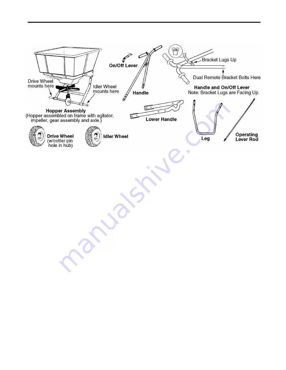
Remove the spreader components from the
carton. You should find all of the parts shown
above plus the Hardware Package.
The Hardware Package contains:
2.
Place a spacer washer on each side of the axle
next to the axle bushing. Mount the drive wheel on
the side of the axle with the predrilled hole near
the axle bushing as shown in the illustration.
Attach by fastening on the inside of the wheel with
the 3/16 x1-3/4 cotter pin.
3.
Mount the idler wheel on the other side of the axle.
Add a spacer washer and put the 3/16 x 1-1/4
cotter pin through the axle on the outside of the
wheel and spacer washer.
4.
Mount the leg to the hopper assembly by fastening
with four 1/4-20 x 2-1/4 hex head cap screws and
four 1/4-20 locknuts. Use eight 1/4 flat washers
under the heads of the cap screws and under the
locknuts.
5.
Mount the lower handle to the hopper assembly by
fastening with four 1/4-20 x 5/8 Phillips head
machine screws and four 1/4-20 locknuts.
6.
Attach the handle (with the on/off bracket lugs
facing up) to the lower handle using four 1/4-20 x
1-1/2 Phillips head machine screws and four 1/4-
20 locknuts. Use eight 1/4 flat washers under the
heads of the machine screws and under the
locknuts.
7.
Fasten the on/off lever to the handle's bracket lugs
using the clevis pin in the bottom hole of the lever.
Insert the clevis pin from left to right, facing the
rear of the hopper. Lock with the 3/32 x 1/2 cotter
pin.
8.
Attach the operating lever rod assembly to the
lever rod adjusting bracket at the bottom-rear of
the hopper. First insert clevis pin through hole in
lever rod adjusting bracket, than place flat washer
on to clevis pin. Insert clevis pin through top hole
in bellcrank pivot and secure with flat washer and
cotter pin.
9.
Attach the operating lever rod to the on/off lever
by inserting the bent end of the rod into the top
hole of the lever from left to right and install the C-
clip. Pull the on/off lever to the off position and set
the main slide plate to the fully closed position by
adjusting the 5/16 hex nuts on the bottom of the
operating lever rod.
10. Attach the dual remote bracket to the lower right
side of the handle using a 1/4-20 x 1-1/2 Phillips
head machine screw and a 1/4-20 locknut.
11. Insert the screen into the hopper.
1
Cotter Pin, 3/16 x 1-3/4
1
Cotter Pin, 3/16 x 1-1/4
3
Spacer Washers, 3/4 I.D.
4
Cap Screws, 1/4-20 x 2-1/4, Hex Head
4
Machine Screws, 1/4-20 x 5/8, Phillips Head
5
Machine Screws, 1/4-20 x 1-1/2, Phillips Head
16
Flat Washers, 1/4
13
Hex Nuts, 1/4-20, Nylock
2
Clevis Pin, 1/4 x 1/2
2
Cotter Pin, 3/32 x 1/2
2
Cable Ties
1
C-Clip


