background image

20

SECTION 9:  OFF-SEASON STORAGE

If the machine is to be inoperative for a period longer 
than 30 days, prepare for storage as follows.

Riding Mower

Clean the engine and the entire unit thoroughly.

NOTE:  We do not recommend the use of pressure
washers or garden hose to clean your unit. These may
cause damage to electrical components, spindles,
pulleys, bearings or the engine. The use of water may
shorten life of equipment and reduce its serviceability.

Lubricate all pivot points. Wipe the entire 
machine with an oiled rag to protect the surfaces.

Store unit in a clean, dry area. Do not store next 
to corrosive materials, such as fertilizer.

When storing any type of power equipment in an 
unventilated or metal storage shed, care should 
be taken to rustproof the equipment. Using a light 
oil or silicone, coat the equipment, especially any 
chains, springs, bearings and cables.

Battery

Charge battery fully. The battery loses some of 
its charge each day when the unit is not used. 
NEVER store battery without a full charge. 
Recharge battery before returning to service or 
every two months, whichever occurs first.

When storing unit for extended periods, 
disconnect battery cables and remove the battery 
from the unit.

Clean dirt and chaff from cylinder, cylinder head 
fins, blower housing, rotating screen and muffler 
area.

Engine

Refer to the engine manual for storage 
instructions. Make sure to store the engine 
properly so that your equipment can work 
smoothly afterwards. 

SECTION 10:  TROUBLE-SHOOTING

Trouble

Possible Cause

Remedial Action

Excessive vibration

1.

Bent or damaged blade

2.

Bent blade.

1.

Stop engine immediately. Check all 
pulleys, blade adapters, keys and bolts for 
tightness and spindle damage. Tighten or 
replace any damaged parts.

2.

Stop engine immediately. Replace 
damaged blade. Only use original 
equipment blades.

Mower will not 
discharge grass or 
leaves uncut strips

1.

Engine speed low.

2.

Speed selection.

3.

Cutting height set too low.

4.

Blades short or dull.

1.

Throttle must be set at full throttle.

2.

Use lower ground speed. Slower the 
ground speed, better the quality of cut.

3.

Raise the deck.

4.

Sharpen or replace blades (uncut strip 
problem only).

Broken Belt

1.

Sudden stop or shock load to belt

2.

Incorrect belt used

3.

Belt engaged abruptly

4.

Defective or damaged belt

1.

Inspect rider for cause such as foreign 
objects stuck in between deck and frame or 
belt path. Remove obstruction and check  
for damage. Replace belt if needed.

2.

Replace with proper belt. Check Parts list 
in this manual for correct part number.

3.

Engage belt slowly by depressing the 
blade engagement pedal slowly.

4.

Replace with proper belt. Follow 
instructions on page 16.

Belt comes off

1.

Belt too loose; stretched

2.

Broken or weak idler spring

1.

Readjust belt. Replace if needed. Follow 
instructions for belt replacement on page 
16.

2.

Replace. Order with correct part number 
from Parts List in this manual.

Summary of Contents for 344 Series

Page 1: ...ark arrester meeting applicable local or state laws if any If a spark arrester is used it should be maintained in effective working order by the operator In the State of California the above is requir...

Page 2: ...Visit mtdproducts com for many useful suggestions Click on Customer Support button and you will get the four options reproduced here Click on the appropriate button and help is immediately available T...

Page 3: ...n off blade s when not mowing Stop engine and wait until blade s comes to a complete stop before a removing grass catcher or unclogging chute or b making any repairs adjusting or removing any grass or...

Page 4: ...l remain where you last saw them Keep children out of the mowing area and in watchful care of an adult other than the operator Be alert and turn machine off if children enter the area Before and when...

Page 5: ...g Do not change the engine governor settings or overspeed the engine Excessive engine speeds are dangerous Observe proper disposal laws and regulations Improper disposal of fluids and materials can ha...

Page 6: ...ly 2 1 2 feet every 10 feet A riding mower could overturn and cause serious injury If operating a walk behind mower on such a slope it is extremely difficult to maintain your footing and you could sli...

Page 7: ...See Figure 1 NOTE Do not lift the hood assembly by the two vent openings located behind the seat Figure 1 Remove wing nut from front battery hold down rod Slide the battery cover towards the rear to...

Page 8: ...that the mulch plug is aligned correctly within the discharge chute Tighten both wing nuts Attaching Bumper Remove bumper from inside the grass catcher Loosen and remove the two pairs of hex bolts and...

Page 9: ...clipping in the bag and when to stop and empty it Parking Brake Use to stop the mower from moving while parked WARNING The operation of any riding mower can result in foreign objects being thrown int...

Page 10: ...al engage parking brake shut engine off and remove key Using Shift Lever This lever is used to regulate direction of the riding mower It can be set at forward neutral or reverse settings These setting...

Page 11: ...the hood assembly above the left rear wheel Refer to Figure 2 Starting Engine Attach the wire to the spark plug Depress the brake pedal with your right foot Set throttle choke control in the CHOKE po...

Page 12: ...on the blade engagement pedal with your left foot while sitting on the operator s seat The recommended mowing pattern is given here Mow grass often and in regular intervals so that you can cut only 1...

Page 13: ...position Pivot the hood assembly up and remove the grasscatcher bag and the side discharge chute or the mulching plug from the mower Disconnect wire from the spark plug Locate the speed control cable...

Page 14: ...t pedal about 3 4 loosen the two hex nuts on the cable See Figure 10 If the belt is engaging sooner than when the blade engagement pedal is 3 4 from the PTO switch tighten both hex nuts on the cable S...

Page 15: ...lace the deck in the highest position Wearing a pair of heavy work gloves to prevent injury rotate the cutting blade so that it is pointed front to back and parallel to the rider Depress and lock the...

Page 16: ...up and remove the grass catcher Remove the spark plug wire Put the deck at the lowest cutting height by adjusting the cutting height adjustment lever to the lowest position Using a 1 2 socket wrench r...

Page 17: ...rminals clean and free of corrosive build up After cleaning apply a light coat of petroleum jelly or grease to both terminals If removing the battery for any reason disconnect the NEGATIVE black wire...

Page 18: ...e solenoid See Figure 15 With the battery charger off connect the positive lead of the charger cable to this terminal See Figure 15 Connect negative lead of the charger cable to the throttle bracket T...

Page 19: ...e to clean your unit These may cause damage to electrical components spindles pulleys bearings or the engine The use of water may shorten life of equipment and reduce its serviceability Lubrication Se...

Page 20: ...anual for storage instructions Make sure to store the engine properly so that your equipment can work smoothly afterwards SECTION 10 TROUBLE SHOOTING Trouble Possible Cause Remedial Action Excessive v...

Page 21: ...eck fluid level in battery If fluid level is low fill to just below split rings with water Charge with 6 Amp charger until fully charged If this does not work replace battery 4 Replace fuse following...

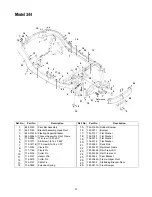
Page 22: ...SECTION 11 PARTS LIST FOR MODEL 344 26 8 34 2 10 42 19 11 1 6 7 28 37 5 20 37 44 35 41 45 33 39 30 14 3 15 36 31 17 29 18 13 6 1 12 12 47 25 48 27 25 40 16 24 46 22 41 32 17 31 21 4 7 43 23 41 32 9 4...

Page 23: ...ex Nut 18 712 0267 Hex Nut 19 712 0324 Lock Nut 1 4 20 20 712 0411 Lock Nut 21 712 0711 Jam Nut 22 714 0470 Cotter Pin 23 723 0156 Ball Joint 24 726 3046 Ratchet Clip 25 731 0511 Trim Strip 26 735 026...

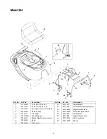
Page 24: ...odel 344 41 7 28 40 3 40 28 13 52 29 11 27 10 25 19 15 39 33 51 18 5 20 30 48 44 22 16 14 17 43 23 21 42 12 8 32 49 37 12 26 6 2 54 12 30 13 35 47 28 40 1 24 11 12 36 34 40 28 11 31 4 28 12 46 45 38 5...

Page 25: ...er 411 x 1 25 x 100 26 736 0159 5 16 Washer 27 736 0169 Lock Washer 28 736 0187 Flat Washer 29 736 0262 Flat Washer 30 736 0272 Flat Washer 510 X 1 00 X 060 31 736 0300 Flat Washer 32 736 0329 Lock Wa...

Page 26: ...712 0130 Lock Nut 11 712 3048 Jam Nut 12 714 0104 Cotter Pin 13 714 0147 Cotter Pin 14 714 3010 Cotter Pin 15 720 0298 Handle Grip 16 732 0829 Extension Spring 17 732 0837 Torsion Spring 18 783 0438...

Page 27: ...625 7 710 1611B TT Screw 5 16 18 x 0 75 8 711 0332 Clevis Pin 9 711 1165 Clevis Pin 10 714 0104 Cotter Pin 11 714 0147 Hairpin Clip 12 714 0470 Cotter Pin 13 725 0157 Cable Tie 14 732 0829 Extension...

Page 28: ...36 0247 Flat Washer 19 736 0322 Flat Washer 20 736 0427 Beleville Washer 21 737 0288 Grease 22 737 3007 Grease Alvania 23 738 0968 Shoulder Spacer 24 741 0405 Thrust Bearing 25 750 0705 Slv Spacer 26...

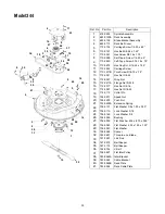
Page 29: ...29 Model 344 35 39 43 20 12 12 29 2 1 21 48 47 11 14 36 31 5 28 12 29 33 29 27 4 8 44 15 22 34 22 41 9 13 24 23 5 42 18 30 40 40 15 46 25 17 14 6 37 7 38 26 3 21 33 7...

Page 30: ...0 5 12 710 1611B TT Screw 5 16 18 x 0 75 13 710 1502 AB Screw 8 18 x 0 375 14 711 04143 Battery Hold Down Rod 15 712 0271 Sems Nut 16 712 0291 Hex Lock Nut 1 4 20 17 712 0397 Wing Nut 18 721 0208 Exh...

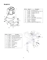
Page 31: ...04016 Seat Low Back 17 738 04008 Spacer Ref No Part No Description Ref No Part No Description 1 710 0599 TT Screw 1 4 20 x 0 5 2 710 1315 TT Screw 3 8 16 x 1 25 3 710 1017 Torx AB Screw 1 4 14 x 0 62...

Page 32: ...Housing Assembly 4 611 0114 Detent Shaft Assembly 5 661 0006 Brake Yoke Assembly LH 6 710 1206 Hex Washer Hd TT Screw 1 4 20 x 2 37 7 710 1325 Hex Washer Hd TT Screw 1 4 20 x 1 65 8 717 0678 Brake Pu...

Page 33: ...Torx Screw 5 16 18 x 75 13 712 0241 Hex Nut 3 8 24 14 712 0397 Wing Nut 15 712 0417A Flange Nut 5 8 18 16 712 3017 Hex Nut 3 8 16 17 712 3057 Hex Nut 5 16 24 18 714 0115 Cotter Pin 19 726 0201 Speed...

Page 34: ...r 12 736 0329 Lock Washer 13 783 0645A Deflector Plate Bagger Chute 6 8 9 10 7 3 11 12 5 13 2 1 8 3 5 10 12 1 2 7 6 4 9 13 11 2 Ref No Part No Description 1 629 0865 Harness Assembly Adapter 2 710 120...

Page 35: ...lt 100 amp 8 725 1643 Spring Switch 9 725 1657A Switch Interlock 10 736 0607 Lock Washer 5 16 11 725 1704 Battery not shown Ref No Part No Description 1 2 3 4 5 6 7 7 10 8 9 Ref No Part No Description...

Page 36: ...justments and normal deterioration of the exterior finish due to use or exposure d Service completed by someone other than an authorized service dealer e MTD does not extend any warranty for products...

Reviews: