9
•
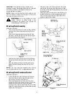
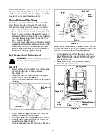
Adjust the chute directional control bracket so that
the spiral on the chute directional control fully
engages the teeth on the chute assembly. Tighten
all hardware. See Figure 10.
•
Check to make sure all nuts and bolts on the control
panel and all four bolts which secure the handles to
the frame are very tight.
Figure 10
Attaching Lamp Wire
(If equipped)
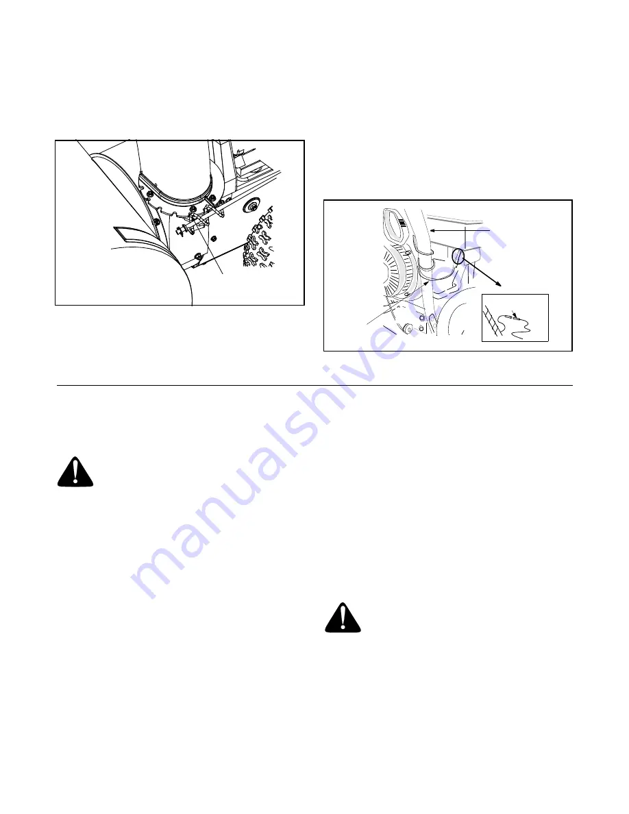
If for shipping purposes, the headlight wire was left
unattached to the alternator lead, follow the steps
below to attach it now:
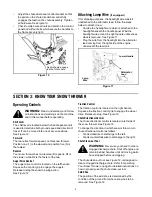
•
Unwrap the headlight wire which is attached to the
headlight beneath the handle panel. Wind the
headlight wire around the right handle until excess
slack is removed. See Figure 11.
•
Plug the wire from the headlight into the alternator
lead coming from the right side of the engine,
underneath the fuel tank.
Figure 11
SECTION 3: KNOW YOUR SNOW THROWER
Operating Controls
WARNING:
Read, understand, and follow
all instructions and warnings on the machine
and in this manual before operating.
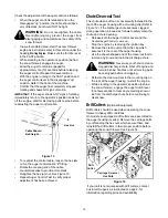
Shift Lever
The shift lever is located below the handle panel and it
is used to determine both ground speed and direction of
travel. It can be moved into one of seven positions.
See Figure 12.
Forward
There are five forward speeds on this snow thrower.
Position one (1) is the slowest and position five (5) is
the fastest.
Reverse
Your snow thrower has two reverse (R) speeds. R1 is
the slower, while R2 is the faster of the two.
Auger Drive Control
The auger drive control is located on the left handle.
Squeeze the control grip to engage the augers.
Release to stop the snow throwing action.
See Figure 12.
Traction Control
The traction control is located on the right handle.
Squeeze the traction control grip to engage the wheel
drive. Release to stop. See Figure 12.
Chute Directional Control
The chute directional control is located on left side of
the snow thrower. See Figure 12.
To change the direction in which snow is thrown, turn
chute directional control as follows:
•
Crank clockwise to discharge to the left.
•
Crank counterclockwise to discharge to the right.
Chute Clean-out Tool
WARNING:
Never use your hand to clear a
clogged discharge chute. Shut off engine and
remain behind handles until all moving parts
have stopped before unclogging.
The chute clean-out tool, see Figure 12, is designed to
clear a clogged discharge chute. Refer to Operating
Your Snow Thrower on page for detailed instructions on
how to properly use the chute clean-out tool.
Skid Shoe
The position of the skid shoe is determined by the
condition of the ground from where snow has to be
removed. See Figure 12.
Spiral should engage
teeth of chute here.
Lower Handle
Alternator
Lead
Lamp
Wire


