16
S
ection
4 — P
roduct
c
are
5.
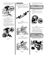
Remove the oil drain plug and drain the oil
into a suitable container with a capacity of
no less than 64 oz.
6.
Tip the riding mower slightly in the
direction of the suitable container to aid in
fully draining all of the oil from the engine.
WARNING
Before tipping engine or equipment to drain oil, drain fuel
from tank by running engine until fuel tank is empty.
7.
Replace the oil drain plug and tighten. Be
careful not to overtighten the oil drain plug.
8.
Refill the engine with new oil as instructed
in the Engine Operator’s Manual packed
with your riding mower.
Note: Refer to the Engine Operator’s
Manual packed with your riding mower for
information regarding the quantity and
proper viscosity of motor oil.
Lubrication
WARNING
Before lubricating, repairing, or inspecting, always disengage
PTO, move shift lever into neutral position, set parking brake,
stop engine and remove key to prevent unintended starting.
Engine
Lubricate the engine with motor oil as instructed
in the Engine Operator’s Manual packed with your
riding mower.
Pivot Points & Linkage
Lubricate all the pivot points on the drive system,
parking brake and lift linkage at least once a
season with light oil.
Rear Wheels
The rear wheels should be removed from the axles
once a season. Lubricate the axles and the rims well
with an all-purpose grease before re-installing them.
Front Axles
Each end of the riding mower’s front pivot bar may be
equipped with a grease fitting. Lubricate with a grease
gun after every 25 hours of riding mower operation.
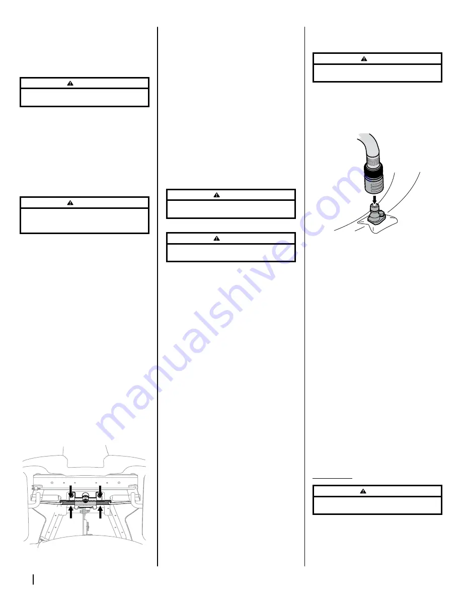
Steering Rack & Pinion
Once per season, or every 25 hours of operation,
it will be necessary to lubricate the steering rack
and pinion gear (a) located under the front of the
riding mower. Using standard automotive grease,
apply grease to the front side and rear side of the
steering rack and pinion gear (a), as indicated in
Figure 4-2.
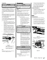
(a)
Figure 4-2
Cleaning the Tractor
If the engine has been running, allow it to cool for
at least half an hour before cleaning. Periodically
remove dirt build-up from engine. Clean cooling fins
every 25 hours. Clean with a brush or compressed air.
Important: Do not spray engine with water to clean
because water could contaminate fuel. Using a
garden hose or pressure washing equipment can also
force water into the air cleaner or muffler opening.
Water in the air cleaner will soak the paper element,
and water that passes through the element or
muffler can enter the cylinder, causing damage.
Any fuel or oil spilled on the machine should
be wiped off promptly. Do NOT allow debris to
accumulate around the cooling fins of the engine
or on any other part of the machine.
Important: The use of a pressure washer to clean
your riding mower is NOT recommended. It may
cause damage to electrical components, spindles,
pulleys, bearings or the engine.
WARNING
Accumulation of debris around muffler could cause a fire.
Inspect and clean before every use.
Muffler
WARNING
Temperature of muffler and nearby engine areas may exceed
150˚F (65˚C). Avoid contact with these areas.
Inspect muffler periodically, and replace if necessary.
Replacement parts for the muffler must be the same
and installed in the same position as the original parts.
Battery
Clean the battery by removing it from the riding
mower and washing with a baking soda and
water solution. If necessary, scrape the battery
terminals with a wire brush to remove deposits.
Coat terminals and exposed wiring with grease or
petroleum jelly to prevent corrosion.
The battery is sealed and is maintenance-free. Acid
levels cannot be checked.
•
Always keep the battery cables and terminals
clean and free of corrosive build-up.
•
After cleaning the battery and terminals,
apply a light coat of petroleum jelly or grease
to both terminals.
•
Always keep the rubber boot positioned over
the positive terminal to prevent shorting.
Important: If removing the battery for any
reason, disconnect the NEGATIVE (Black)
wire from it’s terminal first, followed by
the POSITIVE (Red) wire. When re-installing
the battery, always connect the POSITIVE
(Red) wire its terminal first, followed by
the NEGATIVE (Black) wire. Be certain that
the wires are connected to the correct
terminals; reversing them could change
the polarity and result in damage to your
engine’s alternating system.
Deck Wash System (If equipped)
Your riding mower’s deck is equipped with a water
port on its surface as part of its deck wash system.
Use the deck wash system to rinse grass clippings
from the deck’s underside and prevent the buildup
of corrosive chemicals. Complete the following
steps AFTER EACH MOWING:
1.
Drive the riding mower to a level, clear spot
on your lawn, near enough for your garden
hose to reach.
CAUTION
Make certain the riding mower’s discharge chute is directed
AWAY from your house, garage, parked cars, etc.
2.
Disengage the PTO (Blade Engage), set the
parking brake and stop the engine.
3.
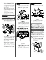
Thread the hose coupler (a) (packaged with
the Operator’s Manual) onto the end of your
garden hose (b). See Figure 4-3.
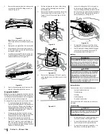
(c)
(a)
(b)
Figure 4-3
4.
Attach the hose coupler (a) to the water port (b)
on your deck’s surface. See Figure 4-3.
5.
Turn the water ON.
6.
While sitting in the operator’s position on
the riding mower, start the engine and
place the throttle lever in the FAST (rabbit)
position.
7.
Move the riding mower’s PTO into the ON
position.
8.
Remain in the operator’s position with the
cutting deck engaged for a minimum of
two minutes, allowing the underside of the
cutting deck to thoroughly rinse.
9.
Move the riding mower’s PTO into the OFF
position.
10.
Turn the ignition key to the STOP position to
turn the riding mower’s engine OFF.
11.
Turn the water OFF and detach the hose
coupler (a) from the water port (c) on your
deck’s surface. See Figure 4-3.
12.
After cleaning your deck with the deck wash
system, return to the operator’s position
and engage the PTO. Keep the cutting deck
running for a minimum of two minutes,
allowing the underside of the cutting deck
to thoroughly dry.
Adjustments
WARNING
Never attempt to make any adjustments while the engine is
running, except where specified in the Operator’s Manual.
Seat
Refer to the Set-Up & Assembly section of this
manual for seat adjustment instructions.
Summary of Contents for 769-11837A
Page 20: ...Notes 4 ...
Page 40: ...Notas 20 ...


