2.
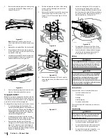
Install the deck chute (b) into the deck
discharge opening on the deck. The rear of
the chute (b) should be under the tab (f) on
the rear deck bracket (g). The studs (c) on the
deck surface will fit through the holes on
the upper portion of the deck chute (b).
The small tab (d) on the deck lip area will
fit through the square cutout on the lower
portion of the deck chute (b). See Figure 2-9.
Note: Make certain that the upper-rear
portion of deck chute (b) is depressing the
safety switch (e) located on the deck surface
and under the tab (f) on the rear deck
bracket (g). The engine will not start without
the deck chute (b) properly in place.
3.
Secure the deck chute (b) by tightening
the wing knobs (a) removed in step 1. See
Figure 2-9.
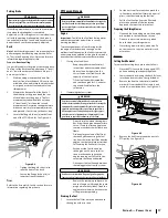
Installing the Mulch Plug (If equipped)
WARNING
Never operate this riding mower without either the mulch
plug or deck chute installed.
1.
Remove the wing knobs (a) installed on
the mowing deck and retain for later
installation. See Figure 2-10.
(a)
(a)
(b)
(c)
(c)
(d)
(e)
(f)
(g)
Figure 2-10
2.
Install the mulch plug (b) into the deck
discharge opening on the deck. The rear of
the mulch plug (b) should be under the tab (f)
on the rear deck bracket (g). The studs (c) on
the deck surface will fit through the holes
on the upper portion of the mulch plug (b).
The small tab (d) on the deck lip area will
fit through the square cutout on the lower
portion of the mulch plug (b). See Figure 2-10.
Note: Make certain that the upper-rear
portion of mulch plug (b) is depressing the
safety switch (e) located on the deck surface
and under the tab (f) on the rear deck
bracket (g). The engine will not start without
the mulch plug (b) properly in place.
3.
Secure the mulch plug (b) by tightening the
wing knobs (a) removed in step 1.
Install the Rear Engine Cover (If equipped)
1.
Remove the two factory installed hex
screws (a) located on the rear engine cover (b).
Retain the hex screws (a) for later instructions.
See Figure 2-11.
(a)
(a)
(b)
Figure 2-11
2.
Install the rear engine cover (b) by
positioning it in place as shown in Figure
2-11 Tip the rear engine cover (b) forward to
fit it into the slots provided, then rotate it
backwards to align the mounting holes.
3.
Secure the rear engine cover (b) with the
two hex screws (a) removed in Step 1. Do
not over-tighten.
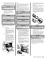
Installing the Hitch Plate
1.
Slide the hitch plate (a) in between the
frame (b) and the rear cover (c) on your rider.
See Figure 2-12.
(a)
(d)
(c)
(b)
(d)
Figure 2-12
2.
When the holes in the hitch plate (a) and the
frame (b) are aligned, install the two hex screws
(d) up through the frame (b) and into the hitch
plate (a). See Figure 2-12.
3.
Securely tighten the hex screws (d).
Installing the Bumper (If equipped)
1.
Remove the two screws (a) as shown in
Figure 2-13.
(a)
(a)
(b)
Figure 2-13
2.
Position the bumper (b) over the mounting
holes and secure using the screws (a)
removed in Step 1. See Figure 2-13.
Connecting the Battery Cables
WARNING
California Proposition 65 Warning: Battery posts, terminals,
and related accessories contain lead and lead compounds,
chemicals known to the State of California to cause cancer
and reproductive harm. Wash hands after handling
CAUTION
When attaching battery cables, always connect the
POSITIVE (Red) wire to its terminal first, followed by the
NEGATIVE (Black) wire.
For shipping reasons, both battery cables on your
equipment may have been left disconnected from
the terminals at the factory. To connect the battery
cables, proceed as follows:
Note: The positive battery terminal is marked POS.
(+). The negative battery terminal is marked NEG. (–).
1.
Remove the factory installed hex bolts (a)
and sems nuts (b) located on the end of the
wiring harness. Retain the hardware for later
instructions. See Figure 2-14.
(a)
(a)
(b)
(b)
(c)
(c)
(d)
(e)
(f)
(g)
Figure 2-14
Summary of Contents for 769-11837A
Page 20: ...Notes 4 ...
Page 40: ...Notas 20 ...


